EP0362894B1 - Staubsauger und Verfahren zu dessen Betrieb - Google Patents
Staubsauger und Verfahren zu dessen Betrieb Download PDFInfo
- Publication number
- EP0362894B1 EP0362894B1 EP89118650A EP89118650A EP0362894B1 EP 0362894 B1 EP0362894 B1 EP 0362894B1 EP 89118650 A EP89118650 A EP 89118650A EP 89118650 A EP89118650 A EP 89118650A EP 0362894 B1 EP0362894 B1 EP 0362894B1
- Authority
- EP
- European Patent Office
- Prior art keywords
- level setting
- driven blower
- electric driven
- setting value
- vacuum cleaner
- Prior art date
- Legal status (The legal status is an assumption and is not a legal conclusion. Google has not performed a legal analysis and makes no representation as to the accuracy of the status listed.)
- Expired - Lifetime
Links
- 238000000034 method Methods 0.000 title claims description 21
- 238000001514 detection method Methods 0.000 claims description 71
- 230000004044 response Effects 0.000 claims description 22
- 230000035945 sensitivity Effects 0.000 claims description 15
- 230000003247 decreasing effect Effects 0.000 claims description 13
- 230000008859 change Effects 0.000 claims description 3
- 230000033001 locomotion Effects 0.000 description 23
- 230000003068 static effect Effects 0.000 description 23
- 238000004140 cleaning Methods 0.000 description 14
- 230000007423 decrease Effects 0.000 description 5
- 244000145845 chattering Species 0.000 description 4
- 239000000428 dust Substances 0.000 description 4
- 230000009467 reduction Effects 0.000 description 4
- 238000010276 construction Methods 0.000 description 3
- 230000007704 transition Effects 0.000 description 3
- 238000007796 conventional method Methods 0.000 description 2
- 230000000694 effects Effects 0.000 description 2
- 230000006698 induction Effects 0.000 description 2
- 230000001360 synchronised effect Effects 0.000 description 2
- 230000007547 defect Effects 0.000 description 1
- 239000012530 fluid Substances 0.000 description 1
- 230000008569 process Effects 0.000 description 1
- 238000011144 upstream manufacturing Methods 0.000 description 1
Images



Classifications
-
- A—HUMAN NECESSITIES
- A47—FURNITURE; DOMESTIC ARTICLES OR APPLIANCES; COFFEE MILLS; SPICE MILLS; SUCTION CLEANERS IN GENERAL
- A47L—DOMESTIC WASHING OR CLEANING; SUCTION CLEANERS IN GENERAL
- A47L9/00—Details or accessories of suction cleaners, e.g. mechanical means for controlling the suction or for effecting pulsating action; Storing devices specially adapted to suction cleaners or parts thereof; Carrying-vehicles specially adapted for suction cleaners
- A47L9/28—Installation of the electric equipment, e.g. adaptation or attachment to the suction cleaner; Controlling suction cleaners by electric means
-
- A—HUMAN NECESSITIES
- A47—FURNITURE; DOMESTIC ARTICLES OR APPLIANCES; COFFEE MILLS; SPICE MILLS; SUCTION CLEANERS IN GENERAL
- A47L—DOMESTIC WASHING OR CLEANING; SUCTION CLEANERS IN GENERAL
- A47L9/00—Details or accessories of suction cleaners, e.g. mechanical means for controlling the suction or for effecting pulsating action; Storing devices specially adapted to suction cleaners or parts thereof; Carrying-vehicles specially adapted for suction cleaners
- A47L9/28—Installation of the electric equipment, e.g. adaptation or attachment to the suction cleaner; Controlling suction cleaners by electric means
- A47L9/2836—Installation of the electric equipment, e.g. adaptation or attachment to the suction cleaner; Controlling suction cleaners by electric means characterised by the parts which are controlled
- A47L9/2842—Suction motors or blowers
-
- A—HUMAN NECESSITIES
- A47—FURNITURE; DOMESTIC ARTICLES OR APPLIANCES; COFFEE MILLS; SPICE MILLS; SUCTION CLEANERS IN GENERAL
- A47L—DOMESTIC WASHING OR CLEANING; SUCTION CLEANERS IN GENERAL
- A47L9/00—Details or accessories of suction cleaners, e.g. mechanical means for controlling the suction or for effecting pulsating action; Storing devices specially adapted to suction cleaners or parts thereof; Carrying-vehicles specially adapted for suction cleaners
- A47L9/02—Nozzles
-
- A—HUMAN NECESSITIES
- A47—FURNITURE; DOMESTIC ARTICLES OR APPLIANCES; COFFEE MILLS; SPICE MILLS; SUCTION CLEANERS IN GENERAL
- A47L—DOMESTIC WASHING OR CLEANING; SUCTION CLEANERS IN GENERAL
- A47L9/00—Details or accessories of suction cleaners, e.g. mechanical means for controlling the suction or for effecting pulsating action; Storing devices specially adapted to suction cleaners or parts thereof; Carrying-vehicles specially adapted for suction cleaners
- A47L9/10—Filters; Dust separators; Dust removal; Automatic exchange of filters
- A47L9/19—Means for monitoring filtering operation
-
- A—HUMAN NECESSITIES
- A47—FURNITURE; DOMESTIC ARTICLES OR APPLIANCES; COFFEE MILLS; SPICE MILLS; SUCTION CLEANERS IN GENERAL
- A47L—DOMESTIC WASHING OR CLEANING; SUCTION CLEANERS IN GENERAL
- A47L9/00—Details or accessories of suction cleaners, e.g. mechanical means for controlling the suction or for effecting pulsating action; Storing devices specially adapted to suction cleaners or parts thereof; Carrying-vehicles specially adapted for suction cleaners
- A47L9/28—Installation of the electric equipment, e.g. adaptation or attachment to the suction cleaner; Controlling suction cleaners by electric means
- A47L9/2805—Parameters or conditions being sensed
- A47L9/2821—Pressure, vacuum level or airflow
Definitions
- the present invention relates to a vacuum cleaner having a detection sensor for detecting an operation condition of the vacuum cleaner in a cleaner main body and a method for operating a vacuum cleaner.
- the present invention relates to a vacuum cleaner and a method for operating the same, the vacuum cleaner comprising a detection sensor for detecting an operation condition in the vacuum cleaner and having an electric driven blower and a control unit for controlling the electric driven blower in response to a detection value of the detection sensor.
- Such a vacuum cleaner is described, for example in DE-A-1 920 640.
- the above stated vacuum cleaner comprises the pressure sensor for detecting the operation condition of the electric driven blower and a control portion for controlling the electric driven blower in response to the detection value of the pressure sensor.
- EP-A-0 264 728 teaches how to control a vacuum cleaner by detecting from the rotational speed and current input to the electric blower and from fluctuations thereof the nature of the surface being cleaned and setting operating conditions accordingly.
- the return level and the change-over level have nearly the same value. Also, the change-over level setting point and the new operating point vary along the same load curve line. Accordingly, a chattering phenomenon is caused in the conventional vacuum cleaner.
- control change-over points are different depending on whether the air flow rate is increasing or decreasing to, so that a hysteresis phenomenon arises. It is therefore difficult to carry out the control of the output of the electric driven blower with a high degree of accuracy.
- the electric driven blower generates a negative pressure according to a centrifugal fan rotating at a high speed by an electric motor and creating a suction force.
- an aerodynamic characteristic of the electric driven blower in the cleaner main body as motion curves in Fig. 5 show, in case that it is driven by an electric motor having a series characteristic such a commutator motor, since the load thereof becomes light at a small air flow rate, a rotation number N rises, also a static pressure H rises. Besides, the electric power consumption W decreases.
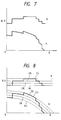
- characteristic curves as shown in Fig. 7 may be obtained by combining pieces of characteristic curves at constant speed control.
- each rate of amounts ⁇ H, ⁇ N, ⁇ W etc. which is respectively a variation of the amount of the static pressure H, the rotation number N, or the electric power consumption W with respect to the air flow variation amount ⁇ Q differs for large air flow rates and for small air flow rates, respectively.
- An object of the present invention is to provide a vacuum cleaner and a method for operating the same wherein an electric driven blower installed in a cleaner main body can be operated with an optimum characteristic.
- Another object of the present invention is to provide a vacuum cleaner and a method for operating the same wherein an output of an electric driven blower installed in a cleaner main body can be decreased at both large air flow rates and small air flow rates.
- a further object of the present invention is to provide a vacuum cleaner and a method for operating the same wherein an output of an electric driven blower installed in a cleaner main body can be decreased using one detection sensor for detecting an operation condition of the vacuum cleaner.
- a further object of the present invention is to provide a vacuum cleaner and a method for operating the same wherein a hysteresis phenomenon in an electric driven blower installed in a cleaner main body can be prevented.
- a further object of the present invention is to provide a vacuum cleaner and a method for operating the same wherein a hysteresis amount in an electric driven blower installed in a cleaner main body can be adjusted.
- a further object of the present invention is to provide a vacuum cleaner and a method for operating the same wherein a chattering phenomenon in an electric driven blower installed in a cleaner main body can be prevented.
- a further object of the present invention is to provide a vacuum cleaner and a method for operating the same wherein an output of an electric driven blower installed in a cleaner main body can be controlled accurately in response to a cleaning condition of the vacuum cleaner.
- a further object of the present invention is to provide a vacuum cleaner and a method for operating the same wherein, an erroneous control for an electric driven blower installed in a cleaner main body, which is caused by varying the rate of variation of a static pressure, a rotation number, an electric power consumption, or an electric current etc. with respect to the rate of variation of an air flow at a large air flow rate side and also at a small air flow rate, may be prevented.
- a vacuum cleaner comprising a cleaner main body having a filter for catching dusts and an electric driven blower within a main case, a detection sensor for detecting an operation condition in the cleaner main body, and a control apparatus for controlling an output of the electric driven blower in response to a detection value of the detection sensor, in which as control values in accordance with the detection value of the detection sensor, a change-over level setting value for forming a judgment point for changing over a control condition of the electric driven blower and a return level setting value for forming a judgment point for returning to a previous control condition of the electric driven blower from a changed-over control condition of the electric driven blower, and an output of the electric driven blower is controlled by the change-over level setting value and the return level setting value.
- the return level setting value is set higher than the change-over level setting value.
- the return level setting value is set a lower than the change-over level setting value.
- a vacuum cleaner comprising a sensor for detecting an operating condition in a cleaner main body having an electric driven blower, and a control portion for controlling the electric driven blower in response to a detection value of the detection sensor
- the detection sensitivity of the detection sensor is varied in response to a suction air flow rate.
- the return level setting value can be set to a predetermined return value in response to a newly changed-over control condition, it is possible to return to an operating point which is close to an operating point at change-over time; so it is possible to control the output of the electric driven blower at same or substantially same air flow range, thereby the hysteresis phenomenon in the electric driven blower can be prevented.
- a detection sensitivity of the detection sensor is varied in response to a suction air flow rate, and a detection output having substantially same level in the electric driven blower can be obtained at all air flow rates.
- an erroneous control caused by the rate of variation of the various parameters which is respectively a variation in the amount of the static pressure, the rotation number, the electric power consumption, or the electric current with respect to the variation in the air flow variation amount at the large air flow range and at the small air flow range is avoided, and an erroneous control of the electric driven blower due to the incorrect judgment is also prevented and further an output control for the electric driven blower can be carried out accurately in response to the condition of the surface to be cleaned.
- a cleaner main body 1 of a vacuum cleaner comprises a main case 3 having an electric driven blower 2 installed in it, and a dust case 5 having a filter 4 for catching dusts installed in it, and the cleaner main body 1 is connected to a hose 6, an extension pipe 7, and a suction nozzle 8.
- the suction nozzle 8 is a general one for use on a floor, a suction nozzle 9 for use in clearance, and a suction nozzle 10 for use on a shelf, each connected to the cleaner main body 1 as attachment parts.
- a control apparatus 11 in the cleaner main body 1 is constructed of electronic circuits including a central execution processing apparatus such as electric circuits or a microcomputer and the control apparatus 11 controls an output of the electric driven blower 2 in response to a detection value of a pressure sensor 12.
- the pressure sensor 12 detects an operating condition of the vacuum cleaner.
- a setting location of the pressure sensor 12 is positioned at a downstream portion of the filter 4 as shown in figure, however the pressure sensor 12 may be suitably provided in the dust case 5 or at an upstream portion of a side of the suction nozzle 8 for use in floor cleaning.
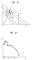
- a control sequence route is shown in Fig. 10.
- the horizontal axis shows an air flow amount Q and the vertical axis shows a static pressure H of each portion of the vacuum cleaner.
- Fig. 10 shows a method for increasing the output of the electric driven blower 2.
- a motion curve B in Fig. 10 shows a static pressure characteristic at a portion of the suction nozzle 8 for use on a floor.
- a characteristic curve C shows a static pressure characteristic detected by the pressure sensor 12 and has pressure values higher than those of the motion curve line B by the sum of the pressure losses in each of the portions at the filter 4, the dust case 5, the hose 6, and the extension pipe 7.
- a new operating point occurs at an intersection point C'1 with the load curve shown in the curve D which is the sum of the above stated pressure loss and the static pressure assumes a value H'1. After this, the operating point moves along the characteristic curve C'.
- the blower motor does not return to the previous control condition.
- the air flow rate Q1 at the change-over level setting point C1 in the forth transition differs from the air flow rate Q2 at the return point C'2 in the return transition, accordingly the hysteresis occurs in the conventional vacuum cleaner.
- a return point C' R is set with an approximate value H' R a little smaller than the value H'1.
- the air flow rate has a value Q R .
- a comparator for setting the change-over level and a comparator for setting the return level may be provided and a logic construction using both comparators may be made.
- one comparator may be provided and a logic construction may be made in which, after the change-over motion the judgment value is replaced by the return level setting value.
- the judgment function may be carried out by a program.
- Fig. 11 shows a method for realizing the negative gradient characteristic against the characteristic of the electric driven blower 2, namely a method for decreasing the output of the electric driven blower 2.
- the references of each characteristic curve B, C, B'', and C'' are the same ones as those shown in Fig. 10.
- a new operating point C''3 is reached and the value of the static pressure becomes H''3.
- a control for returning to the previous motion curve line C may be carried out.
- the pressure value is set at a lower value H'' R from a predetermined value than H''3, so that it is possible to carry out the motion on the motion curve C''.
- the cleaner returns to the previous motion curve line C or a control sequence route.
- dashed line E shows a maximum output line of the electric driven blower 2.
- a range R1 in Fig. 12 shows a practical range for the suction nozzle 8 for use in floor and an optimum control for the vacuum cleaner is carried out.
- the cleaner control responds to the load condition of the above stated suction nozzle 9, when the suction nozzle 9 is rapidly and repeatedly moved to and released from the cleaning surface, the output of the electric driven blower 2 rises to maximum when the suction nozzle 9 returns to the surface.
- the pressure in the portion of the pressure sensor 12 can respond in the integrated style to the pressure fluctuation due to adhesion and release of the suction nozzle portion, because of a time delay in the detection of a rise of total pressure due to a volume of the passage portion between the suction nozzle portion and the sensor. Accordingly, the issue of an unnecessarily rapid output variation command to the electric blower motor is avoided, thus preventing the above stated chattering problem.
- the suction nozzle 9 When the suction nozzle 9 is operated slowly, it can operate with a high output condition as stated above, therefore it is possible to carry out a new use in which the suction force can be adjusted according to the operation speed of the suction nozzle 9.
- a range R3 corresponds to a nearly closed condition of the nozzle and lies outside the practical range. As in this range the output of the electric driven blower 2 is lowered as shown in Fig. 12, it is possible to prevent the suction nozzle 9 for use in clearance from adhering. When the adhesion is released, high output operation is automatically resumed.
- a characteristic curve shown in Fig. 12 the details of which are enlarged is realized by combining a very large number of the basic motions or control sequence routes shown in Fig. 10 and Fig. 11, however if the number of the combined basic motions is small, a smooth motion curve line cannot obtained.
- the motion curve can be realised with a plurality of the electric circuits, however an ideal characteristic motion curve is easily realized by executing a program in the central execution processing apparatus of the microcomputer.
- each change-over level setting point or each return level setting point is stored as a table in the microcomputer, and a successive write-in renewal method for operating the vacuum cleaner can be realized with a small sized apparatus.
- the detection value is detected by only one pressure sensor 12, it is possible to realize the characteristic for the electric driven blower 2 having a negative gradient characteristic.
- FIG. 13 A basic motion or a control sequence route of the vacuum cleaner is shown in Fig. 13 taking into account various pressure losses.
- the horizontal axis in Fig. 13 shows an air flow amount Q, and the vertical axis shows a static pressure H at each portion of the vacuum cleaner.
- a motion curve line A1 shows a static pressure characteristic in each portion of the suction nozzle 8 for use on floor.
- a characteristic curve B1 shows a static pressure characteristic detected by the pressure sensor 12.
- the characteristic curve B1 has a pressure value which is higher than that of the motion curve line A1 by the sum of a pressure loss at the suction nozzle 8 portion, a pressure loss at the filter 4, a pressure loss at the dust case 5, a pressure loss at the hose 6, and a pressure loss at the extension pipe 7.
- the pressure sensor 12 detects the pressure value on the characteristic curve line B1.
- the reason is that, at the large air flow rate, the fluctuation width at each condition is large, namely the air flow variation amount ⁇ Q and the pressure variation amount ⁇ H are large, because the air flow amount Q is large and the opening area of the suction nozzle 8 varies.
- the absolute value of the pressure loss of the suction nozzle 8 portion is small and the fluctuation width becomes small because the air flow amount Q is small.
- the steady pressure value H1 is small, and the fluctuation pressure value ⁇ H1 becomes large.
- the steady pressure value H1 is obtained in the case when the suction nozzle 8 for use on a floor is lifted up in the air so that the fluid resistance is small and therefore no fluctuation with time occurs.
- the fluctuation width and the variation time interval (variation pattern) of the pressure are detected by the pressure sensor 12, they are multiplied at a predetermined level and are sent to the control apparatus 11.
- the control apparatus 11 due to the combination of the microcomputer and the judgment program, judges the kinds of the suction nozzles, the condition of the surface of the item to be cleaned, and the existence of the cleaning operation (the operation is carried out when the suction nozzle 9 is used in clearance or not).
- the control apparatus 11 controls the output of the electric driven blower 2 so as to suit the cleaning condition of the vacuum cleaner and also to obtain the optimum operation condition for the vacuum cleaner.
- the steady pressure value H2 is made large by the clogging of the filter 4 etc., and the fluctuation pressure value ⁇ H2 becomes small.
- the variation width of the pressure is very small and the judgment is difficult or becomes impossible.
- the judgment program may be prepared in response to each air flow range, however the number of programs corresponding to each aerodynamic characteristic becomes enormous, therefore this is not a practical solution.
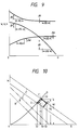
- each of the characteristic groups (as shown in the above stated Fig. 8), turning an attention to the rate ⁇ H/ ⁇ Q of the pressure amount variation ⁇ H in respect with the air flow amount variation ⁇ Q at the large air flow rate and at the small air flow rate, show the same tendency, namely the detection sensitivity of the pressure sensor 12 varies at the small air flow rate.
- the pressure variation ⁇ H, the air flow amount variation ⁇ Q, each of which has substantially same level, or the fluctuation width of the variation rate ⁇ H/ ⁇ Q having substantially same level at all air flow amount area can be obtained by varying the detection sensitivity of the pressure sensor 12.
- the fluctuation width of the output of the pressure sensor 12 at the small air flow rates is made to have substantially the same fluctuation width as the output in the pressure sensor 12 at the large air flow rates.
- the detection sensitivity of the pressure sensor 12 is varied in accordance to the suction air flow rate. Therefore a detection output having substantially the same level of the pressure sensor 12 can be obtained at all air flow ranges.
- the above stated detection sensitivity variation of the pressure sensor 12 is attained by detecting a predetermined air flow rate point, and corresponding to this, by varying the gain of the amplifier, which is included in the pressure sensor 12. It is possible to carry out the detection sensitivity change-over operation for the pressure sensor 12 by the electric circuits constituting the change-over judgment circuit, or by the command in the microcomputer.
- the steady pressure value part H2 is amplified, however it is possible to process the execution by the electric circuits or the microcomputer, by taking out the fluctuation pressure value part from the remaining the steady pressure value part.
- the detection sensitivity of the detection sensor is varied in response to a suction air flow rate, and a detection output having substantially the same level for the detection sensor can be obtained at all air flow rates.
- the detection of the pressure variation by the pressure sensor 12 is given as example, however in place of this detection the air flow rate variation may be detected by using the air flow rate detection sensor.
- control is carried out by detecting the variation amount of the operation conditions in respect to the rotation number variation, the electric power consumption variation, and the electric current variation etc., by the difference in the variation rate at the large air flow rates and at the small air flow rates is equalized and detected, the same effects as those in the above stated embodiment of the present invention can be obtained.
- a detection sensitivity of the detection sensor is varied in response to a suction air flow rate, and a detection output having substantially the same level can be obtained at all air flow rates.
Landscapes
- Engineering & Computer Science (AREA)
- Mechanical Engineering (AREA)
- Electric Vacuum Cleaner (AREA)
Claims (9)
- Staubsauger mit einem Staubsaugerhauptkörper (1), der einen Filter (4) zum Auffangen von Staub und ein elektrisch angetriebenes Gebläse (2) in einem Hauptgehäuse (3) aufweist, mit einem Erfassungssensor (12) zum Erfassen eines Betriebszustands in dem Staubsaugerhauptkörper (1) und einer in dem Staubsaugerhauptkörper (1) vorgesehenen Steuereinheit (11) zum Steuern des Durchsatzes des elektrisch angetriebenen Gebläses (2) in Reaktion auf einen Erfassungswert des Erfassungssensors (12),
dadurch gekennzeichnet,
daß die folgenden Steuerwerte gemäß dem Erfassungswert des Erfassungssensors (12) eingestellt werden:
ein Umschaltniveaueinstellwert (H₁, H₃) zum Bilden eines Beurteilungspunkts zum Umschalten eines Steuerzustands des elektrisch getriebenen Gebläses (2),
ein Rückkehrniveaueinstellwert (HR', HR'') zum Bilden eines Beurteilungspunkts zum Zurückkehren zu einem früheren Steuerzustand des elektrisch angetriebenen Gebläses (2) von einem umgeschalteten Steuerzustand des elektrisch angetriebenen Gebläses (2),
wobei der Durchsatz des elektrisch angetriebenen Gebläses (2) durch den erhaltenen Umschaltniveaueinstellwert (H₁, H₃) und den erhaltenen Rückkehrniveaueinstellwert (HR', HR'') gesteuert wird. - Staubsauger nach Anspruch 1,
dadurch gekennzeichnet,
daß, wenn der Erfassungswert des Erfassungssensors (12) oberhalb des Umschaltniveaueinstellwerts (H₁) liegt, der Durchsatz des elektrisch angetriebenen Gebläses (2) erhöht wird und der Rückkehrniveaueinstellwert (HR') auf einen höheren Wert als der Umschaltniveaueinstellwert (H₁) eingestellt wird. - Staubsauger nach Anspruch 1,
dadurch gekennzeichnet,
daß, wenn der Erfassungswert des Erfassungssensors (12) über dem Umschaltniveaueinstellwert (H₃) liegt, der Durchsatz des elektrisch angetriebenen Gebläses (2) erniedrigt wird und der Rückkehrniveaueinstellwert (HR'') auf einen niedrigeren Wert als der Umschaltniveaueinstellwert (H₃) eingestellt wird. - Staubsauger nach Anspruch 1,
dadurch gekennzeichnet,
daß, wenn der Erfassungswert des Erfassungssensors (12) über dem Umschaltniveaueinstellwert (H₁, H₃) liegt, der Durchsatz des elektrisch angetriebenen Gebläses und der Rückkehrniveaueinstellwert geändert werden, daß eine Steuereinheit (11) vorgesehen ist, um anhand einer Saugluftströmungsrate zu bestimmen, ob der Durchsatz des elektrisch angetriebenen Gebläses (2) erhöht wird und der Rückkehrniveaueinstellwert höher als der Umschaltniveaueinstellwert eingestellt wird, oder ob der Durchsatz des elektrisch angetriebenen Gebläses (2) verringert wird und der Rückkehrniveaueinstellwert niedriger als der Umschaltniveaueinstellwert eingestellt wird. - Staubsauger nach einem der Ansprüche 1 bis 4,
dadurch gekennzeichnet,
daß die Steuereinheit (11) eine zentrale Verarbeitungsausführungseinheit ist, in der der Umschaltniveaueinstellwert (H₁, H₃) und der Umkehrniveaueinstellwert (HR', HR'') gespeichert sind, wobei das elektrisch angetriebene Gebläse (2) durch Zurückstellen des Umschaltniveaueinstellwerts (H₁, H₃), des Rückkehrniveaueinstellwerts (HR', HR'') oder beider auf einen vorgegebenen Wert gesteuert wird. - Staubsauger nach Anspruch 5,
dadurch gekennzeichnet,
daß die zentrale Ausführungsverarbeitungseinheit ein Mikrocomputer ist. - Staubsauger nach Anspruch 5,
dadurch gekennzeichnet,
daß der Durchsatz des elektrisch angetriebenen Gebläses (2) durch die zentrale Ausführungsverarbeitungseinheit gesteuert wird. - Staubsauger nach einem der Ansprüche 1 bis 7,
dadurch gekennzeichnet,
daß der Erfassungssensor (12) ein Drucksensor zum Erfassen eines Drucks in dem Staubsaugerhauptkörper (1) ist. - Verfahren zum Betreiben eines Staubsaugers mit einem Sensor zum Erfassen eines Betriebszustands in einem Staubsaugerhauptkörper (1) mit einem Filter (4) und einem elektrisch angetriebenen Gebläse (2) und einem im Staubsaugerhauptkörper (1) vorgesehenen Steuerabschnitt (11) zum Steuern des elektrisch angetriebenen Gebläses in Reaktion auf einen Erfassungswert eines Erfassungssensors (12),
dadurch gekennzeichnet,
daß eine Erfassungsempfindlichkeit des Erfassungssensors (12) in Abhängigkeit von einer Saugluftströmungsrate verändert wird, und
daß die Erfassungsempfindlichkeit des Erfassungssensors (12) um so höher ist, je niedriger die Saugluftströmungsrate ist.
Applications Claiming Priority (4)
| Application Number | Priority Date | Filing Date | Title |
|---|---|---|---|
| JP63251816A JP2609700B2 (ja) | 1988-10-07 | 1988-10-07 | 電気掃除機の制御方法 |
| JP251816/88 | 1988-10-07 | ||
| JP1066723A JP2521348B2 (ja) | 1989-03-18 | 1989-03-18 | 電気掃除機の運転方法 |
| JP66723/89 | 1989-03-18 |
Publications (3)
| Publication Number | Publication Date |
|---|---|
| EP0362894A2 EP0362894A2 (de) | 1990-04-11 |
| EP0362894A3 EP0362894A3 (de) | 1991-04-24 |
| EP0362894B1 true EP0362894B1 (de) | 1994-07-06 |
Family
ID=26407919
Family Applications (1)
| Application Number | Title | Priority Date | Filing Date |
|---|---|---|---|
| EP89118650A Expired - Lifetime EP0362894B1 (de) | 1988-10-07 | 1989-10-06 | Staubsauger und Verfahren zu dessen Betrieb |
Country Status (4)
| Country | Link |
|---|---|
| US (1) | US5155885A (de) |
| EP (1) | EP0362894B1 (de) |
| KR (1) | KR950001963B1 (de) |
| DE (1) | DE68916607T2 (de) |
Families Citing this family (16)
| Publication number | Priority date | Publication date | Assignee | Title |
|---|---|---|---|---|
| DE3902647A1 (de) * | 1989-01-21 | 1990-08-02 | Interlava Ag | Vorrichtung zur automatischen saugleistungssteuerung eines staubsaugers |
| EP0458057B1 (de) * | 1990-04-16 | 1995-02-01 | Hitachi, Ltd. | Verfahren zum Betreiben eines Staubsaugers |
| DE4237150A1 (de) * | 1992-11-04 | 1994-05-05 | Licentia Gmbh | Staubsauger |
| US5507067A (en) * | 1994-05-12 | 1996-04-16 | Newtronics Pty Ltd. | Electronic vacuum cleaner control system |
| DE19813434A1 (de) * | 1998-03-27 | 1999-09-30 | Proair Geraetebau Gmbh | Naßsauger |
| US7673368B2 (en) * | 2005-10-18 | 2010-03-09 | Panasonic Corporation Of North America | Dust bag arrangement and filling indicator for floor care apparatus |
| EP2491840A2 (de) * | 2006-09-11 | 2012-08-29 | Panasonic Corporation | Elektrischer Reiniger |
| DE102007041067A1 (de) * | 2007-08-30 | 2009-03-05 | BSH Bosch und Siemens Hausgeräte GmbH | Verfahrbare Vorrichtung zum Durchführen von Arbeiten an vorzugsweise ebenen Flächen |
| DE102007059930B3 (de) * | 2007-12-04 | 2009-02-19 | Kurz, Gerhard | Vorrichtung zur Steuerung oder Regelung der Motorleistung eines Staubsaugers |
| DE102008005150B4 (de) * | 2008-01-18 | 2013-09-26 | BSH Bosch und Siemens Hausgeräte GmbH | Staubsauger und Verfahren zum Betreiben eines Staubsaugers |
| DE102010038577B4 (de) * | 2010-07-28 | 2012-02-23 | BSH Bosch und Siemens Hausgeräte GmbH | Vorrichtung und Verfahren zum Betreiben eines Staubsaugers |
| DE102011052020A1 (de) * | 2011-07-21 | 2013-01-24 | Miele & Cie. Kg | Staubsauger und Verfahren zum Betrieb eines Staubsaugers |
| US10375901B2 (en) | 2014-12-09 | 2019-08-13 | Mtd Products Inc | Blower/vacuum |
| JP2022540232A (ja) | 2019-07-11 | 2022-09-14 | シャークニンジャ オペレーティング エルエルシー | スマートノズルおよびスマートノズルを実装する表面クリーニング装置 |
| SE544198C2 (en) * | 2019-11-14 | 2022-03-01 | Husqvarna Ab | Improved dust extractor motor control |
| GB2596856B (en) * | 2020-07-10 | 2023-01-04 | Dyson Technology Ltd | Vacuum cleaner |
Family Cites Families (17)
| Publication number | Priority date | Publication date | Assignee | Title |
|---|---|---|---|---|
| US1904973A (en) * | 1931-06-29 | 1933-04-18 | Hoover Co | Suction cleaner |
| US2789660A (en) * | 1954-05-12 | 1957-04-23 | Electrolux Corp | Automatic vacuum cleaners |
| US3577869A (en) * | 1967-08-09 | 1971-05-11 | Matsushita Electric Industrial Co Ltd | Electric vacuum cleaner |
| DE1920640A1 (de) * | 1969-04-23 | 1970-11-05 | Philips Patentverwaltung | Staubsauger mit einem elektromotorisch angetriebenen Geblaese |
| DE2032476A1 (de) * | 1970-07-01 | 1972-01-05 | Licentia Gmbh | Staubsauger, dessen Kompressordrehzahl sich selbsttätig an die verschiedenen Arbeitsprozesse anpaßt |
| US4021879A (en) * | 1975-11-28 | 1977-05-10 | Consolidated Foods Corporation | Constant performance vacuum cleaner |
| JPS5463558A (en) * | 1977-10-31 | 1979-05-22 | Tokyo Electric Co Ltd | Vacuum cleaner |
| DE3030059C2 (de) * | 1980-08-08 | 1984-06-07 | Progress-Elektrogeräte Mauz & Pfeiffer GmbH & Co, 7000 Stuttgart | Staubsauger |
| DE3030066C2 (de) * | 1980-08-08 | 1983-07-07 | Progress-Elektrogeräte Mauz & Pfeiffer GmbH & Co, 7000 Stuttgart | Drehzahlregeleinrichtung für einen Gebläsemotor eines Staubsaugers |
| DD203462A1 (de) * | 1981-11-09 | 1983-10-26 | Oberlind Veb Elektroinstall | Steuerschaltung fuer einen staubsauger mit elektronischem drehzahlsteller |
| DE3225463A1 (de) * | 1982-07-07 | 1984-01-12 | Siemens AG, 1000 Berlin und 8000 München | Staubsauger mit einer regel- oder steuereinrichtung fuer den motor des geblaeseaggregates |
| DE3431175C2 (de) * | 1984-02-08 | 1986-01-09 | Gerhard 7262 Althengstett Kurz | Schutzvorrichtung für Staubsammeleinrichtungen |
| DE3431164A1 (de) * | 1984-02-08 | 1985-08-14 | Gerhard 7262 Althengstett Kurz | Staubsauger |
| JPS61280831A (ja) * | 1985-05-31 | 1986-12-11 | 三洋電機株式会社 | 真空掃除機 |
| US4654924A (en) * | 1985-12-31 | 1987-04-07 | Whirlpool Corporation | Microcomputer control system for a canister vacuum cleaner |
| KR940002923B1 (ko) * | 1986-10-08 | 1994-04-07 | 가부시키가이샤 히타치세이사쿠쇼 | 전기청소기의 운전방법 및 그 장치 |
| DE8901003U1 (de) * | 1989-01-21 | 1989-04-06 | Interlava AG, Lugano | Vorrichtung zur automatischen Saugleistungssteuerung eines Staubsaugers |
-
1989
- 1989-10-03 US US07/416,829 patent/US5155885A/en not_active Expired - Fee Related
- 1989-10-06 EP EP89118650A patent/EP0362894B1/de not_active Expired - Lifetime
- 1989-10-06 DE DE68916607T patent/DE68916607T2/de not_active Expired - Fee Related
- 1989-10-06 KR KR1019890014345A patent/KR950001963B1/ko not_active Expired - Lifetime
Also Published As
| Publication number | Publication date |
|---|---|
| DE68916607T2 (de) | 1994-12-01 |
| EP0362894A3 (de) | 1991-04-24 |
| US5155885A (en) | 1992-10-20 |
| KR950001963B1 (ko) | 1995-03-08 |
| DE68916607D1 (de) | 1994-08-11 |
| KR900005937A (ko) | 1990-05-07 |
| EP0362894A2 (de) | 1990-04-11 |
Similar Documents
| Publication | Publication Date | Title |
|---|---|---|
| EP0362894B1 (de) | Staubsauger und Verfahren zu dessen Betrieb | |
| US6105202A (en) | Intelligent suction device capable of automatically adapting the suction force according to the conditions of the surface, particularly for vacuum cleaners and the like | |
| JP4542628B2 (ja) | 電気ブラシの操作モードに依存する出力制御を有する真空掃除機 | |
| US4958406A (en) | Method and apparatus for operating vacuum cleaner | |
| US5233682A (en) | Vacuum cleaner with fuzzy control | |
| EP0479609A2 (de) | Staubsauger und Verfahren zur Steuerung desselben | |
| KR910007481A (ko) | 전기청소기 | |
| EP0312111A2 (de) | Elektrisches Reinigungsgerät | |
| KR910017996A (ko) | 진공 소제기 | |
| JP2907440B2 (ja) | 吸込み型掃除機 | |
| US4155725A (en) | Dust removal from smoke gas or the like | |
| KR100432790B1 (ko) | 전기청소기 | |
| JP2521348B2 (ja) | 電気掃除機の運転方法 | |
| JP2004177063A (ja) | 空気調和機 | |
| JP2609700B2 (ja) | 電気掃除機の制御方法 | |
| JP2960449B2 (ja) | 電気掃除機 | |
| JP2969729B2 (ja) | 電気掃除機 | |
| JP2537209B2 (ja) | 電気掃除機及び電気掃除機の制御方法 | |
| JPH03131219A (ja) | 電気掃除機 | |
| JPH08228978A (ja) | 電気掃除機 | |
| KR950014842B1 (ko) | 진공청소기의 흡입력 제어방법 | |
| JPH01155822A (ja) | 電気掃除機 | |
| JPH03186244A (ja) | 電気掃除機の電力制御装置 | |
| JPH0121977B2 (de) | ||
| JPS6340094B2 (de) |
Legal Events
| Date | Code | Title | Description |
|---|---|---|---|
| PUAI | Public reference made under article 153(3) epc to a published international application that has entered the european phase |
Free format text: ORIGINAL CODE: 0009012 |
|
| AK | Designated contracting states |
Kind code of ref document: A2 Designated state(s): DE GB |
|
| 17P | Request for examination filed |
Effective date: 19901122 |
|
| PUAL | Search report despatched |
Free format text: ORIGINAL CODE: 0009013 |
|
| AK | Designated contracting states |
Kind code of ref document: A3 Designated state(s): DE GB |
|
| 17Q | First examination report despatched |
Effective date: 19920720 |
|
| GRAA | (expected) grant |
Free format text: ORIGINAL CODE: 0009210 |
|
| AK | Designated contracting states |
Kind code of ref document: B1 Designated state(s): DE GB |
|
| REF | Corresponds to: |
Ref document number: 68916607 Country of ref document: DE Date of ref document: 19940811 |
|
| PLBE | No opposition filed within time limit |
Free format text: ORIGINAL CODE: 0009261 |
|
| STAA | Information on the status of an ep patent application or granted ep patent |
Free format text: STATUS: NO OPPOSITION FILED WITHIN TIME LIMIT |
|
| 26N | No opposition filed | ||
| REG | Reference to a national code |
Ref country code: GB Ref legal event code: IF02 |
|
| PGFP | Annual fee paid to national office [announced via postgrant information from national office to epo] |
Ref country code: GB Payment date: 20030924 Year of fee payment: 15 |
|
| PGFP | Annual fee paid to national office [announced via postgrant information from national office to epo] |
Ref country code: DE Payment date: 20031203 Year of fee payment: 15 |
|
| PG25 | Lapsed in a contracting state [announced via postgrant information from national office to epo] |
Ref country code: GB Free format text: LAPSE BECAUSE OF NON-PAYMENT OF DUE FEES Effective date: 20041006 |
|
| PG25 | Lapsed in a contracting state [announced via postgrant information from national office to epo] |
Ref country code: DE Free format text: LAPSE BECAUSE OF NON-PAYMENT OF DUE FEES Effective date: 20050503 |
|
| GBPC | Gb: european patent ceased through non-payment of renewal fee |
Effective date: 20041006 |