EP0362918B1 - Soupape à papillon avec un joint d'étanchéité élastique pourvu d'un anneau métallique intérieur de renforcement - Google Patents
Soupape à papillon avec un joint d'étanchéité élastique pourvu d'un anneau métallique intérieur de renforcement Download PDFInfo
- Publication number
- EP0362918B1 EP0362918B1 EP89202296A EP89202296A EP0362918B1 EP 0362918 B1 EP0362918 B1 EP 0362918B1 EP 89202296 A EP89202296 A EP 89202296A EP 89202296 A EP89202296 A EP 89202296A EP 0362918 B1 EP0362918 B1 EP 0362918B1
- Authority
- EP
- European Patent Office
- Prior art keywords
- elastomeric material
- seal
- shutter
- metal ring
- sealing
- Prior art date
- Legal status (The legal status is an assumption and is not a legal conclusion. Google has not performed a legal analysis and makes no representation as to the accuracy of the status listed.)
- Expired - Lifetime
Links
- 238000007789 sealing Methods 0.000 title claims abstract description 47
- 239000013536 elastomeric material Substances 0.000 title claims abstract description 35
- 239000002184 metal Substances 0.000 title claims abstract description 27
- 230000002787 reinforcement Effects 0.000 title abstract description 4
- 239000012530 fluid Substances 0.000 claims abstract description 9
- 230000005489 elastic deformation Effects 0.000 claims abstract description 6
- 210000000056 organ Anatomy 0.000 claims abstract description 5
- 238000009434 installation Methods 0.000 claims description 3
- 230000013011 mating Effects 0.000 claims description 2
- 239000007769 metal material Substances 0.000 claims description 2
- 239000000463 material Substances 0.000 description 7
- 238000003825 pressing Methods 0.000 description 4
- XLYOFNOQVPJJNP-UHFFFAOYSA-N water Substances O XLYOFNOQVPJJNP-UHFFFAOYSA-N 0.000 description 3
- 239000007789 gas Substances 0.000 description 2
- 238000003780 insertion Methods 0.000 description 2
- 230000037431 insertion Effects 0.000 description 2
- 238000004519 manufacturing process Methods 0.000 description 2
- 238000000034 method Methods 0.000 description 2
- 238000009966 trimming Methods 0.000 description 2
- 229910001369 Brass Inorganic materials 0.000 description 1
- 230000001133 acceleration Effects 0.000 description 1
- 230000015572 biosynthetic process Effects 0.000 description 1
- 239000010951 brass Substances 0.000 description 1
- 238000009826 distribution Methods 0.000 description 1
- 238000010438 heat treatment Methods 0.000 description 1
- 230000008595 infiltration Effects 0.000 description 1
- 238000001764 infiltration Methods 0.000 description 1
- 230000002262 irrigation Effects 0.000 description 1
- 238000003973 irrigation Methods 0.000 description 1
- 230000007774 longterm Effects 0.000 description 1
- 238000012986 modification Methods 0.000 description 1
- 230000004048 modification Effects 0.000 description 1
- 238000011084 recovery Methods 0.000 description 1
- 238000009877 rendering Methods 0.000 description 1
- 239000003566 sealing material Substances 0.000 description 1
- 230000008961 swelling Effects 0.000 description 1
- 238000003466 welding Methods 0.000 description 1
Images
Classifications
-
- F—MECHANICAL ENGINEERING; LIGHTING; HEATING; WEAPONS; BLASTING
- F16—ENGINEERING ELEMENTS AND UNITS; GENERAL MEASURES FOR PRODUCING AND MAINTAINING EFFECTIVE FUNCTIONING OF MACHINES OR INSTALLATIONS; THERMAL INSULATION IN GENERAL
- F16K—VALVES; TAPS; COCKS; ACTUATING-FLOATS; DEVICES FOR VENTING OR AERATING
- F16K1/00—Lift valves or globe valves, i.e. cut-off apparatus with closure members having at least a component of their opening and closing motion perpendicular to the closing faces
- F16K1/16—Lift valves or globe valves, i.e. cut-off apparatus with closure members having at least a component of their opening and closing motion perpendicular to the closing faces with pivoted closure-members
- F16K1/18—Lift valves or globe valves, i.e. cut-off apparatus with closure members having at least a component of their opening and closing motion perpendicular to the closing faces with pivoted closure-members with pivoted discs or flaps
- F16K1/22—Lift valves or globe valves, i.e. cut-off apparatus with closure members having at least a component of their opening and closing motion perpendicular to the closing faces with pivoted closure-members with pivoted discs or flaps with axis of rotation crossing the valve member, e.g. butterfly valves
- F16K1/226—Shaping or arrangements of the sealing
- F16K1/2263—Shaping or arrangements of the sealing the sealing being arranged on the valve seat
-
- F—MECHANICAL ENGINEERING; LIGHTING; HEATING; WEAPONS; BLASTING
- F16—ENGINEERING ELEMENTS AND UNITS; GENERAL MEASURES FOR PRODUCING AND MAINTAINING EFFECTIVE FUNCTIONING OF MACHINES OR INSTALLATIONS; THERMAL INSULATION IN GENERAL
- F16K—VALVES; TAPS; COCKS; ACTUATING-FLOATS; DEVICES FOR VENTING OR AERATING
- F16K1/00—Lift valves or globe valves, i.e. cut-off apparatus with closure members having at least a component of their opening and closing motion perpendicular to the closing faces
- F16K1/16—Lift valves or globe valves, i.e. cut-off apparatus with closure members having at least a component of their opening and closing motion perpendicular to the closing faces with pivoted closure-members
- F16K1/18—Lift valves or globe valves, i.e. cut-off apparatus with closure members having at least a component of their opening and closing motion perpendicular to the closing faces with pivoted closure-members with pivoted discs or flaps
- F16K1/22—Lift valves or globe valves, i.e. cut-off apparatus with closure members having at least a component of their opening and closing motion perpendicular to the closing faces with pivoted closure-members with pivoted discs or flaps with axis of rotation crossing the valve member, e.g. butterfly valves
- F16K1/224—Details of bearings for the axis of rotation
- F16K1/225—Details of bearings for the axis of rotation the axis of rotation having only one bearing
-
- F—MECHANICAL ENGINEERING; LIGHTING; HEATING; WEAPONS; BLASTING
- F16—ENGINEERING ELEMENTS AND UNITS; GENERAL MEASURES FOR PRODUCING AND MAINTAINING EFFECTIVE FUNCTIONING OF MACHINES OR INSTALLATIONS; THERMAL INSULATION IN GENERAL
- F16K—VALVES; TAPS; COCKS; ACTUATING-FLOATS; DEVICES FOR VENTING OR AERATING
- F16K1/00—Lift valves or globe valves, i.e. cut-off apparatus with closure members having at least a component of their opening and closing motion perpendicular to the closing faces
- F16K1/16—Lift valves or globe valves, i.e. cut-off apparatus with closure members having at least a component of their opening and closing motion perpendicular to the closing faces with pivoted closure-members
- F16K1/18—Lift valves or globe valves, i.e. cut-off apparatus with closure members having at least a component of their opening and closing motion perpendicular to the closing faces with pivoted closure-members with pivoted discs or flaps
- F16K1/22—Lift valves or globe valves, i.e. cut-off apparatus with closure members having at least a component of their opening and closing motion perpendicular to the closing faces with pivoted closure-members with pivoted discs or flaps with axis of rotation crossing the valve member, e.g. butterfly valves
- F16K1/226—Shaping or arrangements of the sealing
- F16K1/2263—Shaping or arrangements of the sealing the sealing being arranged on the valve seat
- F16K1/2265—Shaping or arrangements of the sealing the sealing being arranged on the valve seat with a channel- or U-shaped seal covering a central body portion
Definitions
- the object of this invention is a butterfly valve with a sealing element in elastomeric material with an internal metal reinforcement.
- valves with special required characteristics are widely used.
- Such valves must provide high characteristics of resistance to the fluid also in the presence of high pressures, they must be easily and quickly manouvrable, offer limited head loss in the "open” position and, furthermore, be low cost.
- valves for this purpose the so-called "sphere" valves are widely used, which valves, however, even though offering a good performance, result as relatively expensive, due to the number of parts they are made of and the assembling operations thereof, and require, especially when of larger dimensions, a great deal of stress when manouvering.
- valves which valves feature a substantially disc-shaped shutter, which can be rotated between a position transversal to the flow, where it realizes the interception, and a position parallel to the flow in which the passage is allowed.
- Valves where a gasket in elastomeric material is set integrally to the perimeter of the disc and seals against the inner surface of the valve body are also known; these valves, however, display problems concerning the shutter lock, after a certain period of inactivity, due to the fact that the gasket is restrained in a seating of the shutter contrasting its deformation in one direction while it is solicited in an ortogonal direction to exert its sealing function.
- valves futhermore, result to be costly, as they require mechanical work for both the realization of the housing seating of the gasket on the shutter and the sealing surface of the gasket on the valve body, and also display, due to the space longitudinally occupied by the gasket, high flow head losses.
- Valves of the butterfly type are also known, whith a sealing element made of a ring in elastomeric material housed in the external body, which however presents sealing problems between its outer, smooth surface, and the valve body, because the same seal is realized on a very wide surface and with limited radial loads; infiltrations of fluid between the sealing element and the valve body can moreover determine an inward buckling of the sealing element, which has a scarce rigidity because of its elastic deformability sufficient to ensure proper sealing, and therefore these valves result as suitable only for use at limited pressure values; besides, these valves, due to the characteristics of the sealing material, are used only with water.
- this invention has a butterfly valve comprising a substantially tubular external valve body, with flow pipe connections for fluids at its extremities, an annular seal of elastomeric material located in the valve body and encircling a disc-shaped, internally mobile shutter, equipped with a diametral axis shaft transversal to the valve body axis, protruding out of the same body and bearing the rotation commanding organs, the annular seal being equipped with an inside metal ring, axially extended substantially for the entire length of the seal and with two radially external sealing reliefs or protusions of shim (r), in radial correspondence of which there are related seatings in the valve body, an ample elastic deformation of the elastomeric material of the seal being allowed in the sealed areas, not laterally contrasted, the inside metal ring of the annular seal having a median area, in correspondence with the sealing area in contact with the shutter a relatively thick shim of elastomeric material being provided on the seal between the metal ring and
- the annular seal of elastomeric material presents at least one hole transversal to the axis of the same element, suitable for the passage of the shaft anchored to the shutter, a corresponding hole in the inside metal ring being present, with a larger diameter than the diameter of the hole in the elastomeric material, such as to leave a thickness of elastomeric material between the inner surface of the hole and the metallic material of the inside ring able to allow the installation of the shaft with an elastic swell sufficient to ensure the sealing of the shaft, without exceeding the elastic limit of the elastomeric material.
- the sealing contact areas between the shutter and the annular seal are located laterally to the line of intersection of the same disc with its meridian plane of symmetry.
- the shutter has a diametral hole in which the shutter shaft is inserted and anchored by forced mating, with the aid of a threaded profile on the surface of the same shaft.
- the external sealing reliefs of the annular seal have a semicircular cross-section.
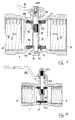
- a valve according to the invention of the kind commonly referred to as “butterfly”, includes an external body 1 , equipped with organs 2,3 connecting to a conduct, for instance of the threaded kind as per illustration, or shaped for other known ways of connection, such as flanges, welding or other.
- a sealing element 4 Inside body 1 there is a sealing element 4 , in which a substantially disc-shaped shutter 5 is put, equipped with a shaft 6 crossing the collar 7 of body 1 and bearing, at the outside extremity, a plug lever 8 .
- the shaft 6 In the form as illustrated in figure 1, suitable for valves of dimensions bigger than a certain value, in relation with the mechanical characteristics of the materials used and the scaling of the parts, for example superior to 1" (25.4 mm), the shaft 6 completely goes across the crossing hole 9 of the shutter, where it is blocked in rotation by the threaded profile 10 , finding housing in a seating 11 inside the body 1 ; in the version shown in figure 2, suitable for valves of smaller dimensions, the shaft 6a supports an overhanging shutter 5a , being it inserted in the related dead hole 12 .
- the sealing in both versions, is ensured by the element 4 , inserted in a related seating of the body 1 and locking elasticly the perimeter of the shutter 5 or 5a , when in "closed” position.
- the element 4 is made of a hollow cylindrical body in elastomeric material 13 , in which a shaped metal ring 14 is incorporated in the pressing phase, extended axially for a prevailing part of its length.
- a radial hole 15 placed in correspondence with the collar 7 , allows the shaft 6 to pass through and, in correspondence with it, a hole 16 (figure 1) permits the shaft to reach seating 11.
- a relief 19 inside the valve body constitutes a ledging surface at an extremity of the sealing element, thus easing the assembly, as described hereinafter.
- the metal ring 14 shows a central portion 14a with a diameter substantially equal to the external diameter of the element 4; at the extremities, on the contrary, the ring 14 shows the portions 14b with an outer diameter inferior to the diameter of the element 4, thus leaving a "d" shim of elastomeric material between the same portions 14b and the outer surface of the element 4.
- such a shim is substantially equal to the "r" protrusion of the reliefs 17 , located at the same extremities, and therefore, between the 14b portion and the supporting surfaces of the seating 18, a thickness of elastomeric material is included, substantially corresponding to the area occupied by a toroidal gasket 20 with a "r+d" diameter, shown in the illustration with a dashed line, thus realizing optimal sealing conditions, similar to the performance offered by an "O-ring" toroidal gasket, well renowned thanks to the width of the elastic total excursion the elastomeric material is permitted.
- the metal ring 14 shows a whole with an inside diameter superior to the diameter of hole 15 or 16, since a "s" shim of elastomeric material has been left between the hole surface and the hole border of the metal ring.
- Such a “s" shim allows an insertion of the 6 or 6a shaft, with elastic deformation of the elastomeric material 13 of the element 4, such as to ensure the sealing on the surface of the same shaft outward, without requiring further gasket elements on the same shaft within the collar 7 .
- the metal ring 14 In its intermediate position 14a the metal ring 14 is designed to leave an "e” thickness of elastomeric material 13 , as shown in figure 4, raised enough to offer an elastic compliance towards the shutter 5 which ensures its sealing capability against its outline when in "closed” position.
- the deformation of the elastomeric material shows a high value; however, the relative deformation, i.e. the ratio between the amplitude of the deformation and the thickness of the material experiencing it, remains within limited values, thanks to the value of the "e" thickness, and also the possibility of swelling of the same material laterally to the shutter is left, as shown, in a magnified form to enhance the phenomenon, in figure 5.
- the structure, according to the invention results furthermore convenient from an economic point of view, by reducing the number of parts of which the valve is made up and permitting a particularly simple assembling, realizable through automated processes.
- the shutter 5, or 5a is inserted with its hole 9 or 12 aligned with the hole 15 and the collar 7, then the shaft 6 or 6a which locks in the shutter through the threaded profile 10 .
- the shutter preferably in brass, by forming, removing the rags in correspondence with the meridian plane by trimming, without any further work on the tool in those areas.
- the elastomeric material of the sealing element tends to assume a continuously curving position, as magnified in figure 5 for greater graphic enhancement, which therefore corresponds to the disjuction from the shutter, or at least to a noticeable decrease of the elastic reaction load on the rough area 22 , which, therefore, is not interested in the seal and whose state of roughness cannot, then, affect the seal itself.
- the presence of the metal reinforcement inside the sealing element allows the elastomeric material it is made of to be chosen based on its best characteristics from the point of view of the seal and the resistance to the fluid, regardless of its mechanical resistance; this permits to use the valve, according to the findings, in presence of various fluids and not just water, as well as gases, compressed air and the like.
Landscapes
- Engineering & Computer Science (AREA)
- General Engineering & Computer Science (AREA)
- Mechanical Engineering (AREA)
- Lift Valve (AREA)
- Gasket Seals (AREA)
Claims (5)
- Vanne à papillon comprenant un corps de vanne externe sensiblement tubulaire (1), avec des liaisons à tube d'écoulement (2, 3) pour des fluides à ses extrémités, un joint d'étanchéité annulaire (4) en matière élastomère placé dans le corps de vanne (1) et entourant un obturateur intérieurement mobile et en forme de disque (5 ; 5a), muni d'un arbre à axe diamétral (6, 6a) transversal à l'axe du corps de vanne, faisant saillie de ce même corps (1) et portant les organes de commande en rotation (8), le joint d'étanchéité annulaire (4) étant muni d'une bague métallique intérieure (14) s'étendant axialement sensiblement sur toute la longueur du joint d'étanchéité (4), et avec deux protubérances ou saillies (17) radialement externes d'étanchéité d'épaisseur (r), en correspondance radiale desquelles se trouvent des sièges (18) dans le corps de vanne (1), une ample déformation élastique de la matière élastomère du joint d'étanchéité (4) étant permise dans les surfaces d'étanchéité, noncontrastées latéralement, la bague métallique intérieure (14) du joint d'étanchéité annulaire (4) présentant une surface médiane en correspondance avec la surface d'étanchéité en contact avec l'obturateur (5 ; 5a), une partie en matière élastomère relativement épaisse étant prévue sur le joint d'étanchéité (4) entre la bague métallique (14) et l'obturateur (5 ; 5a), caractérisée en ce que ladite surface médiane de la bague métallique du joint d'étanchéité annulaire (4) a un diamètre externe sensiblement égal au diamètre externe du joint d'étanchéité (4), et en ce que ladite bague métallique (14) présente deux surfaces d'extrémité, toutes deux en correspondance radiale avec les protubérances d'étanchéité externes (17) du joint d'étanchéité (4), ces surfaces présentant un plus petit diamètre pouvant laisser, entre la surface extérieure du joint d'étanchéité (4) et la surface de la bague métallique (14), une épaisseur de matière élastomère (d) au moins égale aux protubérances d'étanchéité (17) d'épaisseur (r) faisant saillie de la surface du joint d'étanchéité (4).
- Vanne à papillon selon la revendication 1, caractérisée par le fait que le joint d'étanchéité annulaire (4) en matière élastomère présente au moins un trou (15) transversal à l'axe de ce même élément, prévu pour le passage de l'arbre (6) ancré à l'obturateur (5), un trou correspondant à la bague métallique intérieure (14) étant présent, avec un diamètre supérieur au diamètre du trou (15) de la matière élastomère, afin de laisser une épaisseur (s) de matière élastomère (13) entre la surface intérieure du trou et la matière métallique de la bague métallique intérieure pour permettre de placer l'arbre (6 ; 6a) avec une paroi élastique suffisante pour assurer l'étanchéité de l'arbre, sans dépasser la limite élastique de la matière élastomère (13).
- Vanne à papillon selon la revendication 1, caractérisée par le fait que les surfaces de contact d'étanchéité entre l'obturateur (5 ; 5a) et le joint d'étanchéité annulaire (4) sont placées latéralement à la ligne d'insertion de ce même disque avec son plan méridien de symétrie.
- Vanne à papillon selon la revendication 1, caractérisée par le fait que l'obturateur (5a) présente un trou diamétral dans lequel l'arbre (6a) de l'obturateur est inséré et ancré par accouplement à force, à l'aide d'un profilé fileté sur la surface de l'arbre lui-même.
- Vanne à papillon selon la revendication 1, caractérisée par le fait que les protubérances d'étanchéité externes (17) du joint d'étanchéité annulaire (4) présentent une section transversale semi-circulaire.
Priority Applications (1)
| Application Number | Priority Date | Filing Date | Title |
|---|---|---|---|
| AT89202296T ATE99781T1 (de) | 1988-10-06 | 1989-09-13 | Mit einem inneren metallverstaerkungsring versehenes elastisches dichtungselement fuer drosselklappen. |
Applications Claiming Priority (2)
| Application Number | Priority Date | Filing Date | Title |
|---|---|---|---|
| IT8822211A IT1227297B (it) | 1988-10-06 | 1988-10-06 | Valvola a farfalla con elemento di tenuta in materiale elastomerico dotato di rinforzo metallico interno |
| IT2221188 | 1988-10-06 |
Publications (2)
| Publication Number | Publication Date |
|---|---|
| EP0362918A1 EP0362918A1 (fr) | 1990-04-11 |
| EP0362918B1 true EP0362918B1 (fr) | 1994-01-05 |
Family
ID=11193108
Family Applications (1)
| Application Number | Title | Priority Date | Filing Date |
|---|---|---|---|
| EP89202296A Expired - Lifetime EP0362918B1 (fr) | 1988-10-06 | 1989-09-13 | Soupape à papillon avec un joint d'étanchéité élastique pourvu d'un anneau métallique intérieur de renforcement |
Country Status (6)
| Country | Link |
|---|---|
| US (1) | US4998708A (fr) |
| EP (1) | EP0362918B1 (fr) |
| AT (1) | ATE99781T1 (fr) |
| CA (1) | CA1329188C (fr) |
| DE (1) | DE68912051T2 (fr) |
| IT (1) | IT1227297B (fr) |
Families Citing this family (27)
| Publication number | Priority date | Publication date | Assignee | Title |
|---|---|---|---|---|
| US5409654A (en) * | 1993-08-05 | 1995-04-25 | Nibco Inc. | Method of reaction injection molding a valve |
| GB2298023A (en) * | 1995-02-16 | 1996-08-21 | Duriron Co | Adjustable ball valve |
| US6142173A (en) * | 1996-07-30 | 2000-11-07 | Spears Manufacturing Company | High purity corrosion resistant butterfly valve |
| DE19851343A1 (de) * | 1998-11-06 | 2000-05-11 | Wilo Gmbh | Kreiselpumpe mit Absperrklappe |
| IT246930Y1 (it) * | 1999-12-09 | 2002-04-10 | Bonomi Bresciane Rubinetterie | Valvola di intercettazione per fluidi con organo otturatore a farfalla ad elevata affidabilita' di funzionamento |
| RU2180065C2 (ru) * | 2000-03-20 | 2002-02-27 | Сербин Виктор Михайлович | Дисковый поворотный затвор |
| JP4703235B2 (ja) * | 2005-03-31 | 2011-06-15 | 旭有機材工業株式会社 | バタフライバルブ |
| US7758017B2 (en) * | 2007-01-22 | 2010-07-20 | Sure Seal, Inc. | Butterfly valves and construction thereof |
| CN100578051C (zh) * | 2008-09-05 | 2010-01-06 | 无锡市亚迪流体控制技术有限公司 | 角行程旋转盘切阀 |
| WO2011038346A2 (fr) * | 2009-09-25 | 2011-03-31 | Bray International, Inc. | Bague de siège unitaire renforcée pour ensemble soupape |
| DE102010042340A1 (de) * | 2010-10-12 | 2012-04-12 | Krones Aktiengesellschaft | Klappendichtung für ein Scheibenventil |
| ITBS20120165A1 (it) * | 2012-11-27 | 2014-05-28 | Ind Saleri Italo Spa | Gruppo valvola estraibile a tenuta migliorata |
| US20150101687A1 (en) * | 2013-10-16 | 2015-04-16 | Hamilton Sundstrand Corporation | Liquid Valve Design with internal Check Valve |
| GB2520309B (en) * | 2013-11-15 | 2020-09-09 | Chargepoint Tech Limited | Valve Seat |
| US9976666B1 (en) * | 2016-02-10 | 2018-05-22 | Bobby New | Butterfly valve assembly |
| US10408355B2 (en) * | 2017-11-01 | 2019-09-10 | Mueller International, Llc | Pressure activated valve seat |
| US10794494B2 (en) * | 2018-04-10 | 2020-10-06 | Mueller International, Llc | Bonded seat with annular ribs |
| CN109386620B (zh) * | 2018-11-14 | 2025-01-10 | 上海箱箱智能科技有限公司 | 蝶阀 |
| CA3077216A1 (fr) * | 2019-03-29 | 2020-09-29 | Velan Inc. | Robinet a papillon et papillon |
| ES3066237T3 (en) * | 2020-05-21 | 2026-05-12 | Maxitrol Co | Valve seat with seal for use with valve element in valve assembly |
| US11312466B1 (en) | 2020-09-14 | 2022-04-26 | Ltag Systems Llc | Inflatable structure deployment |
| US11958585B1 (en) | 2020-11-25 | 2024-04-16 | Ltag Systems Llc | Midair deployment of aerostats |
| WO2022160161A1 (fr) | 2021-01-28 | 2022-08-04 | Mueller International, Llc | Siège de soupape lié |
| US12296940B2 (en) | 2021-10-17 | 2025-05-13 | Ltag Systems Llc | Lifting gas generation |
| EP4311960A1 (fr) | 2022-07-27 | 2024-01-31 | UTC Aerospace Systems Wroclaw Sp. z o.o. | Vannes papillon |
| US12589853B1 (en) | 2022-12-12 | 2026-03-31 | Ltag Systems Llc | Actively actuatable valves for aerostat buoyancy control |
| US12275516B1 (en) | 2023-02-21 | 2025-04-15 | Ltag Systems Llc | Stabilization and reinforcement of balloons during rapid filling |
Family Cites Families (11)
| Publication number | Priority date | Publication date | Assignee | Title |
|---|---|---|---|---|
| US3311128A (en) * | 1964-02-25 | 1967-03-28 | Daniel Orifice Fitting Company | Butterfly valve |
| US3508737A (en) * | 1968-01-19 | 1970-04-28 | Vapor Corp | Sealing ring retainment and adaptation to a butterfly valve |
| US3537683A (en) * | 1968-11-04 | 1970-11-03 | Keystone Valve Corp | Valve seat for a butterfly valve and method for making the same |
| US3633872A (en) * | 1969-11-24 | 1972-01-11 | Fmc Corp | Butterfly valve |
| US3782684A (en) * | 1971-09-20 | 1974-01-01 | Rockwell International Corp | Seat insert for butterfly-type valves |
| US3840042A (en) * | 1973-02-26 | 1974-10-08 | B Brundage | Butterfly valve |
| US3940108A (en) * | 1974-09-11 | 1976-02-24 | Nibco Inc. | Reinforcement ring and seat for butterfly valve |
| CA1059494A (fr) * | 1977-04-20 | 1979-07-31 | Crane Canada Limited | Vanne a papillon a siege flottant |
| US4225113A (en) * | 1978-10-19 | 1980-09-30 | General Signal Corporation | Butterfly valve having cartridge construction with improved bearings |
| DE3203374C2 (de) * | 1982-02-02 | 1987-04-30 | Mark Controls Corp., 5568 Daun | Sitzring für ein Klappenventil |
| US4685611A (en) * | 1986-11-26 | 1987-08-11 | Keystone International, Inc. | Butterfly valve construction having a composite seat |
-
1988
- 1988-10-06 IT IT8822211A patent/IT1227297B/it active
-
1989
- 1989-06-01 CA CA000601398A patent/CA1329188C/fr not_active Expired - Fee Related
- 1989-09-13 AT AT89202296T patent/ATE99781T1/de not_active IP Right Cessation
- 1989-09-13 EP EP89202296A patent/EP0362918B1/fr not_active Expired - Lifetime
- 1989-09-13 DE DE68912051T patent/DE68912051T2/de not_active Expired - Fee Related
- 1989-09-15 US US07/407,959 patent/US4998708A/en not_active Expired - Fee Related
Also Published As
| Publication number | Publication date |
|---|---|
| US4998708A (en) | 1991-03-12 |
| DE68912051T2 (de) | 1994-08-11 |
| CA1329188C (fr) | 1994-05-03 |
| EP0362918A1 (fr) | 1990-04-11 |
| DE68912051D1 (de) | 1994-02-17 |
| IT8822211A0 (it) | 1988-10-06 |
| ATE99781T1 (de) | 1994-01-15 |
| IT1227297B (it) | 1991-04-05 |
Similar Documents
| Publication | Publication Date | Title |
|---|---|---|
| EP0362918A1 (fr) | Soupape à papillon avec un joint d'étanchéité élastique pourvu d'un anneau métallique intérieur de renforcement | |
| US3131906A (en) | Valve seat | |
| EP0004428B1 (fr) | Boisseau sphérique et vanne avec boisseau et sièges démontables pour température élevée | |
| US4593916A (en) | Sealing device providing the upstream/downstream sealing of a valve | |
| US5370148A (en) | Butterfly valve assembly and method of manufacture | |
| US6217003B1 (en) | Valve assembly having floating retainer rings | |
| EP0244185A2 (fr) | Vanne à soufflet | |
| KR100393295B1 (ko) | 밸브어셈블리 | |
| US4141537A (en) | Valve seat construction for butterfly valves | |
| CA2484210C (fr) | Robinet d'arret configurable sur site | |
| US4177972A (en) | Cocks having rotating manipulation spindles | |
| US6425571B1 (en) | Valve and method for forming valve | |
| AU780313B2 (en) | Backflow prevention assembly | |
| US3913610A (en) | Butterfly valve | |
| CA2023552C (fr) | Soupape et garniture d'etancheite amelioree pour siege de soupape | |
| EP0156581A1 (fr) | Montage d'une vanne papillon | |
| EP1242761B1 (fr) | Ensemble clapet a bagues de retenue flottantes | |
| US3666234A (en) | Spherical disc valve assembly | |
| GB2226619A (en) | Butterfly valves | |
| US3566909A (en) | Between flange ball valves with fixed-unstressed seals | |
| CN218000480U (zh) | 蝶阀锁紧装置 | |
| CN214946438U (zh) | 一种高频开关高性能蝶阀 | |
| KR200334647Y1 (ko) | 세그먼트 플러그형 메탈시트 볼밸브 | |
| EP0137639A1 (fr) | Vanne avec siège elastique | |
| KR100512578B1 (ko) | 밸브를 위한 디스크 기구 및 그를 사용한 게이트 밸브 및글로브 밸브 |
Legal Events
| Date | Code | Title | Description |
|---|---|---|---|
| PUAI | Public reference made under article 153(3) epc to a published international application that has entered the european phase |
Free format text: ORIGINAL CODE: 0009012 |
|
| AK | Designated contracting states |
Kind code of ref document: A1 Designated state(s): AT BE CH DE ES FR GB GR IT LI NL SE |
|
| 17P | Request for examination filed |
Effective date: 19900929 |
|
| 17Q | First examination report despatched |
Effective date: 19920702 |
|
| GRAA | (expected) grant |
Free format text: ORIGINAL CODE: 0009210 |
|
| AK | Designated contracting states |
Kind code of ref document: B1 Designated state(s): AT BE CH DE ES FR GB GR IT LI NL SE |
|
| PG25 | Lapsed in a contracting state [announced via postgrant information from national office to epo] |
Ref country code: SE Effective date: 19940105 Ref country code: LI Effective date: 19940105 Ref country code: GR Free format text: LAPSE BECAUSE OF FAILURE TO SUBMIT A TRANSLATION OF THE DESCRIPTION OR TO PAY THE FEE WITHIN THE PRESCRIBED TIME-LIMIT Effective date: 19940105 Ref country code: ES Free format text: THE PATENT HAS BEEN ANNULLED BY A DECISION OF A NATIONAL AUTHORITY Effective date: 19940105 Ref country code: CH Effective date: 19940105 Ref country code: BE Effective date: 19940105 Ref country code: AT Effective date: 19940105 |
|
| REF | Corresponds to: |
Ref document number: 99781 Country of ref document: AT Date of ref document: 19940115 Kind code of ref document: T |
|
| REF | Corresponds to: |
Ref document number: 68912051 Country of ref document: DE Date of ref document: 19940217 |
|
| ITF | It: translation for a ep patent filed | ||
| REG | Reference to a national code |
Ref country code: CH Ref legal event code: PL |
|
| ET | Fr: translation filed | ||
| PG25 | Lapsed in a contracting state [announced via postgrant information from national office to epo] |
Ref country code: GB Effective date: 19940913 |
|
| PLBE | No opposition filed within time limit |
Free format text: ORIGINAL CODE: 0009261 |
|
| STAA | Information on the status of an ep patent application or granted ep patent |
Free format text: STATUS: NO OPPOSITION FILED WITHIN TIME LIMIT |
|
| PGFP | Annual fee paid to national office [announced via postgrant information from national office to epo] |
Ref country code: DE Payment date: 19941125 Year of fee payment: 6 |
|
| 26N | No opposition filed | ||
| GBPC | Gb: european patent ceased through non-payment of renewal fee |
Effective date: 19940913 |
|
| PGFP | Annual fee paid to national office [announced via postgrant information from national office to epo] |
Ref country code: NL Payment date: 19950929 Year of fee payment: 7 |
|
| PG25 | Lapsed in a contracting state [announced via postgrant information from national office to epo] |
Ref country code: DE Effective date: 19960601 |
|
| PG25 | Lapsed in a contracting state [announced via postgrant information from national office to epo] |
Ref country code: NL Effective date: 19970401 |
|
| NLV4 | Nl: lapsed or anulled due to non-payment of the annual fee |
Effective date: 19970401 |
|
| PGFP | Annual fee paid to national office [announced via postgrant information from national office to epo] |
Ref country code: FR Payment date: 19970930 Year of fee payment: 9 |
|
| PG25 | Lapsed in a contracting state [announced via postgrant information from national office to epo] |
Ref country code: FR Free format text: LAPSE BECAUSE OF NON-PAYMENT OF DUE FEES Effective date: 19990531 |
|
| REG | Reference to a national code |
Ref country code: FR Ref legal event code: ST |
|
| PG25 | Lapsed in a contracting state [announced via postgrant information from national office to epo] |
Ref country code: IT Free format text: LAPSE BECAUSE OF NON-PAYMENT OF DUE FEES;WARNING: LAPSES OF ITALIAN PATENTS WITH EFFECTIVE DATE BEFORE 2007 MAY HAVE OCCURRED AT ANY TIME BEFORE 2007. THE CORRECT EFFECTIVE DATE MAY BE DIFFERENT FROM THE ONE RECORDED. Effective date: 20050913 |