EP0362932B1 - Bathtub having selfsustaining walls - Google Patents
Bathtub having selfsustaining walls Download PDFInfo
- Publication number
- EP0362932B1 EP0362932B1 EP89202428A EP89202428A EP0362932B1 EP 0362932 B1 EP0362932 B1 EP 0362932B1 EP 89202428 A EP89202428 A EP 89202428A EP 89202428 A EP89202428 A EP 89202428A EP 0362932 B1 EP0362932 B1 EP 0362932B1
- Authority
- EP
- European Patent Office
- Prior art keywords
- shell
- tub
- hollow
- bath tub
- ribs
- Prior art date
- Legal status (The legal status is an assumption and is not a legal conclusion. Google has not performed a legal analysis and makes no representation as to the accuracy of the status listed.)
- Expired - Lifetime
Links
Images


Classifications
-
- A—HUMAN NECESSITIES
- A47—FURNITURE; DOMESTIC ARTICLES OR APPLIANCES; COFFEE MILLS; SPICE MILLS; SUCTION CLEANERS IN GENERAL
- A47K—SANITARY EQUIPMENT; ACCESSORIES THEREFOR, e.g. TOILET ACCESSORIES
- A47K3/00—Baths; Showers; Appurtenances therefor
- A47K3/02—Baths
Definitions
- plastic material bathtubs Today there is the use of manufacturing plastic material bathtubs (such as disclosed in the DE-A-2702295) for reasons of low cost and easy working.
- the process used to be followed is that of vacuum thermoshaping through which a plastic material sheet, for example from methyl metacrylate, usually well stiff at ambient temperature as well as at the usual temperature of hot water in a bathtub, is heated to the softening point and laid down against a hollow mold by applying a vacuum at suitable points.
- said modular shell structure is formed by an assembly of protruding and re-entring areas connected by ribs similar to the ribs sustaining a boat planking, which are formed by connecting surfaces between said protruding areas and said re-entring areas, said ribs being arranged in two substantially perpendicular groups each other intersecting in order to form a rectangular grid having substantially uniform members and having the duty of distributing the most uniformely the possible said strains.
- a bathtub manufactured according to the tub 30, having ribbed shell 32 of figure 2.
- Said tub surrounded and supported by a brick structure defined by the tiled walls 66 and 68, comprises a rectangular frame edge 94 from which descends a ribbed shell 96 provided with a first major raised band area 98 arranged according to the length of the tub, and with a second minor raised band area 100 substantially perpendicular with respect to the major band area 98, said band area 100 terminating with two planes 102a and 102b a little below the frame 94 operating as article supporting planes.
Landscapes
- Health & Medical Sciences (AREA)
- Public Health (AREA)
- Epidemiology (AREA)
- General Health & Medical Sciences (AREA)
- Bathtubs, Showers, And Their Attachments (AREA)
- Cultivation Receptacles Or Flower-Pots, Or Pots For Seedlings (AREA)
- Devices For Medical Bathing And Washing (AREA)
Description
- Present invention pertains to bathtubs and in particular bathtubs manufactured from plastic materials.
- Today there is the use of manufacturing plastic material bathtubs (such as disclosed in the DE-A-2702295) for reasons of low cost and easy working. The process used to be followed is that of vacuum thermoshaping through which a plastic material sheet, for example from methyl metacrylate, usually well stiff at ambient temperature as well as at the usual temperature of hot water in a bathtub, is heated to the softening point and laid down against a hollow mold by applying a vacuum at suitable points.
- This process produces tub shells having excellent shape and finishing needing few, if any, further working for having their ultimate appearance and the full utilizability.
- The only serious problem with these so obtained shells is their intrinsic brittleness or weakness, due to wall thinness, preventing their direct use in installations, as said shells could easily open or crack even under relatively mild strains. A largerly used remedy against this problems consists in exterally coating said shells by means of glass fabric layers soaked by hardenable resins, such as polyesters, producing a sustaining structure provided with substantial mechanical strenght in order to however prevent damages to said shell, specifically the ones connected with the use of a bathtub.
- This external coating with glass fabric layers soaked by hardenable resin has however, further to give the external wall of the tub a poor aesthetic appearance, the serious problem of raising the wall thickness thereof to the point to allow just a partial entry of the external part of a tub in the internal part of another tub so that in storing and shipping people are compelled to take into account an encumbrance similar to a parallelepiped enclosing the same, with poor space use problems heavily affecting said storage and shipping costs.
- According to EP-A-126832 the shell of the bathtub is provided with a supporting body, having regularly reinforced ribs forming a grid, onto which the shell abuts.
- To avoid this excessive encumbrance problem should be devised bathtub shells with such a selfsustaining structure to prevent substantial distortions thereof under usual strains due to use or piling-up, but altogether so thin to allow piling-up with entry of any shell in each other leading to both storage and shipping space substantial economies.
- This is achieved by a bathtub comprising a simple completely selfsustaining shell characterized by comprising a strengthening a rib or ridge structure, consisting of a modular grid, having the duty, of uniformely distribute in said shell the strains due to the load of water and , possibly, or a person lying in said tub, said shell modular structure comprising a radial rib assembly depending from a shell edge and joining in at least one point on the bottom thereof, said ribs starting from points distributed on said shell edge in order to form a rectangular grid with substantially uniform members having the duty of distributing the most uniformly the possible said strains.
- In particular, said ribs converging on the bottom are connected each other by curved surfaces, either hollow or convex with respect to the shell inside, giving the shell an appearance as of a sea shell and a particularly high strength.
- Preferably, the curved surfaces connecting said ribs are arranged symmetrically around a longitudinal axis of said shell with a hollow first major surface, symmetrically divided by said longitudinal axis, going from the upper edge at the head side to the convergence point of the ribs on the bottom of the shell, flanked by two hollow curved surfaces in turn adjacent third hollow surfaces continuining in fourth surfaces, which can be either hollow or convex, in turn continuing in fifth hollow surfaces adjacent a last hollow surface symmetrically divided by said shell longitudinal axis at the foot side of the tub.
- More preferably said first hollow major surface is so shaped to form an anatomic back.
- Still more preferably, said two second hollow surfaces, adjacent said first hollow surface, form niches delimited at half height by bottom planes forming two arms.
- Further preferably, said fourth curved convex surfaces end as lowered with respect to the tub edge forming two support planes symmetrically arranged with respect to the longitudinal axis of the tub itself.
- According to a second embodiment, said modular shell structure is formed by an assembly of protruding and re-entring areas connected by ribs similar to the ribs sustaining a boat planking, which are formed by connecting surfaces between said protruding areas and said re-entring areas, said ribs being arranged in two substantially perpendicular groups each other intersecting in order to form a rectangular grid having substantially uniform members and having the duty of distributing the most uniformely the possible said strains.
- Particularly the areas protruding to inside said shell form as two substantially perpendicular bands of which a first major band is parallel and symmetric with respect to a longitudinal axis of said shell and a second minor band is substantially perpendicular with respect to said first major band intersecting it at a place substantially near the foot side of said shell.
- More preferably, said first major band is shaped at the head side of said shell in order to form an anatomic back.
- Still preferably, two re-entring areas adjacent said major band at head side are provided with two niches delimited at half height by bottom planes forming two arms.
- Further preferably, said second protruding minor band ends against the edge of the tub with two lowered areas forming two support planes symmetrically arranged with respect to the longitudinal axis of the shell itself.
- The features and the advantages of the present invention will be made more apparent by the following detailed description of its embodiments, not given in limiting sense provided with the enclosed drawings, wherein:
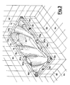
- figure 1 is a diagrammatical perspective view of a selfsustaining tub shell structure according to a first embodiment of present invention;
- figure 2 is a diagrammatical perspective view of selfsustaining tub shell structure according to a second embodiment of present invention;
- figure 3 is a perspective view of an installed bathtub formed by a selfsustaining shell of the first embodiment;
- figure 4 is a perspective view of an installed bathtub formed by a selfsustaining shell of the second embodiment.
- Considering the first embodiment and particularly figure 1, it is seen that the
first tub 10 embodiment, having selfsustaining walls according to the present invention, consists of ashell 12, formed for example by vacuum themoshaping of a thermoplastic material sheet, comprising anedge 14 according to a substantially rectangular frame from which depends ahull 16 forming the part of the tub intended to contain the water. From theedge 14 along the internal walls of the tub depend ribs orridges 18a-l which, starting from points 20a-l on the edge of thehull 16, descend to aconnection area 22 usually strengthened for housing accesories such as the tub drain. The points 20a-l are arranged in order to lay on a grid having rectangular substantially regular loops formed by intersectingstraight lines 24a-e which provides a substantially uniform distribution of the strains on thehull 16 due to the presence of water and or of the body of a person in thetub 10. Of course, saidtub 10 abuts in a usual way with its bottom andedge 14 on astructure 26, such as a brick wall structure tiled or panelled, and also on the floor of the room in which the bathtub is installed. - Considering now the second embodiment of this tub and particularly figure 2 in this case a
selfsustaining wall tub 30 according to the present invention consists of ashell 32 also formed by vacuum thermoshaping from a thermoplastic material sheet, comprising anedge 34 according to a rectangular fram frome which ahull 36, forming the part of the tub intedend to contain water, descends. - The internal walls of the
hull 36 have two inside protruding areas of which a first major area orband 38 is arranged parallel and symmetric with respect to alongitudinal axis 39 of the tub itself and a minor area orband 40 is sustantially perpendicular with respect to themajor area 38 crossing the same near the foot side of the tub. The twoband areas areas 42a-f, of which twoareas areas rib connections 44a-l having a strengthening duty similar to that of the ribs of a boat hull. Therib connections 44a-l are in line withstraight lines 45a-e crossing each other to form a grid having rectangular uniform loops providing a substantially uniform distribution of the strains applied to thehull 36 by the presence of water and/or the body of a person in the bathtub itself. - Of course, said
tub 30, showing on the external wall of itshull 36re-entring band areas 46 and 48 respectively corresponding toband areas edge 34 against astructure 50, such as a brick structure, tilable or panelable for aesthetic purposes, as well as on the floor of the room in which the bathtub is installed. - From the review of figures 1 and 2 it appears that in both the tub embodiments the external walls of the
respective shells shells shells - Referring now to figure 3 it is seen an installed bathtub having ribbed shell embodied according to figure 1 example.
- In a corner of a bathroom between two tiled
vertical walls tiled floor 64, is installed a bathtub manufactured according to thetub 10, having the ribbedshell 12 of figure 1. - Said tub, surrounded and supported by a brick structure, defined by the
tiled walls rectangular frame edge 74 from which descends a ribbedshell 76 provided with ribs protruding to the inside indicating the limits among hollow surfaces such as thesurfaces 78a-h, or between hollow and convex surfaces, such as thesurfaces rectangular edge 74 for defining twoarticle support planes - Further, the
hollow surfaces arms hollow surface 78a is so shaped to form an anatomic back affording particular comfort to the bathtub. - Referring at last to figure 4, it is seen an installed bathtub having a ribbed shell according to the embodiment of figure 2.
- In a corner of a bathroom between two vertical
tiled walls tiled floor 64 is installed a bathtub manufactured according to thetub 30, having ribbedshell 32 of figure 2. Said tub, surrounded and supported by a brick structure defined by thetiled walls rectangular frame edge 94 from which descends a ribbed shell 96 provided with a first major raisedband area 98 arranged according to the length of the tub, and with a second minor raisedband area 100 substantially perpendicular with respect to themajor band area 98, saidband area 100 terminating with twoplanes frame 94 operating as article supporting planes. - At the head side of the tub the raised
band 98 is surrounded by two loweredniches 104a and 104b, terminating at half height with twoplanes 106a, and 106b, operating as arms. - Similarly at the foot side there are two lowered
areas bands 96 and 100. On the bottom of the tub the lowered areas prosecute delimited by the raisedbands band 98 is shaped at the head side to form ananatomic back 110 affording particular comfort to the tub. - A
further thickness step 112 at half height supplies a supplementar orizontal rib further cooperating to strengthen the shell 96. - What has been hereabove stated depictes two embodiments of the invention, given in not limiting sense, and it will appear to those skilled in the art fully equivalent changements, alterations and substitutions, to be considered here covered.
Claims (11)
- Bath tub, having selfsustaining walls, formed by a single shell, characterized by comprising a strengthening rib or ridge structure consisting of a modular grid, having the duty of uniformely distribute in said shell the strains due to the load of water, and possibly of a person lying in said tub, that said shell modular structure comprising a radial rib assembly (18a-l) depending from a shell edge (14) and joining in at least one point (22) of the bottom of the shell, said ribs (18a-l) starting from points (20a-l) distributed along said shell edge (14) in order to form a rectangular grid with substantially uniform members having the duty of distributing the most uniformly the possible said strains.
- Bath tub, according to claim 1, characterized in that said ribs (18a-l) converging on the bottom are connected to each other by curved surfaces, either hollow or convex, giving the shell (12) an appearance as of a sea shell and a particularly high strength.
- Bath tub, according to claim 2, characterized in that the curved surfaces connecting said ribs (18a-l) are arranged symmetrically around a longitudinal axis of said shell (12) with a hollow first surface (78a), symmetrically divided by said longitudinal axis, going from the upper edge (14) at the head side of the tub to the convergence point (22) of the ribs (18a-l) on the bottom of the shell (12), flanked by two hollow curved surfaces (78b, 78h) in turn adjacent third hollow surfaces (78c,78g), continuing in fourth surfaces (80a, 80b), which can be either hollow or convex, in turn continuining in fifth hollow surfaces (78d, 78f) adjacent a last hollow surface (78e) symmetrically divided by said shell (12) longitudinal axis at the foot side of the tub.
- Bath tub , according to claim 3, characterized in that said first hollow major surface (78a) is shaped to form an anatomic back (86).
- Bath tub, according to claim 3, characterized in that said second hollow surfaces (78b, 78h) adjacent said first hollow surface (78a) form niches delimited at half height by bottom planes forming two arms (84,85).
- Bath tub, according to claim 3, characterized in that said fourth surfaces (80a, 80b), if convex form two support planes (82a, 82b) symmetrically arranged with respect to the longitudinal axis of the shell (12).
- Bath tub, having selfustaining walls, formed by a single shell, characterized by comprising a strengthening rib or ridge structure consisting of a modular grid, having the duty of uniformely distribute in said shell the strains due to the load of water, and possibly of a person lying in said tub said modular shell structure being formed by an assembly of protruding areas (38, 40) and re-entring areas (42a-f) connected by ribs (44a-l), similar to the ribs substaining a boat planking, which are formed by connecting surfaces between said protruding areas (38, 40) and said re-entring areas (42a-f), said ribs (44a-l) being arranged in two substantially perpendicular groups each other intersecting in order to form a rectangular grid having substantially uniform members and having the duty of distributing the most uniformely the possible said strains.
- Bath tub, according to claim 7, characterized in that the areas (38, 40) protruding inside said shell (12), are formed as two substantially perpendicular bands of which a first major band (38) is parallel and symmetric with respect to a longitudinal axis (39) of said shell and a second minor band (40) is substantially perpendicular with respect said first major band (38), intersecting it at a place substantially close to the foot side of said shell (12).
- Bath tub, according to claim 8, characterized in that said first major band (38, 98) is shaped at the head side of said shell (32) in order to form an anatomic back (110).
- Bath tub, according to claim 8, characterized in that two re-entring or lowered areas (42a-f) adjacent said major band (38, 98) at the head side are provided with two niches (104a, 104b) delimited at half height by bottom planes forming two arms (106a, 106b).
- Bath tub, according to claim 8 characterized in that said second protruding minor band (40, 100) ends against the edge (34, 94) of the tub with two lower areas (102a, 102b) forming two support planes symmetrically arranged with respect the longitudinal axis of the shell (12) itself.
Applications Claiming Priority (2)
| Application Number | Priority Date | Filing Date | Title |
|---|---|---|---|
| IT8822163A IT1227267B (en) | 1988-10-03 | 1988-10-03 | BATHTUB WITH SELF-SUPPORTING WALLS. |
| IT2216388 | 1988-10-03 |
Publications (2)
| Publication Number | Publication Date |
|---|---|
| EP0362932A1 EP0362932A1 (en) | 1990-04-11 |
| EP0362932B1 true EP0362932B1 (en) | 1993-07-28 |
Family
ID=11192441
Family Applications (1)
| Application Number | Title | Priority Date | Filing Date |
|---|---|---|---|
| EP89202428A Expired - Lifetime EP0362932B1 (en) | 1988-10-03 | 1989-09-28 | Bathtub having selfsustaining walls |
Country Status (4)
| Country | Link |
|---|---|
| EP (1) | EP0362932B1 (en) |
| DE (1) | DE68907842T2 (en) |
| ES (1) | ES2044064T3 (en) |
| IT (1) | IT1227267B (en) |
Cited By (2)
| Publication number | Priority date | Publication date | Assignee | Title |
|---|---|---|---|---|
| WO2005060915A1 (en) * | 2003-12-23 | 2005-07-07 | Jack Layfield | Modular prefabricated spa |
| USD575406S1 (en) | 2003-12-23 | 2008-08-19 | Jack Layfield | Water spa |
Families Citing this family (3)
| Publication number | Priority date | Publication date | Assignee | Title |
|---|---|---|---|---|
| US5101521A (en) * | 1990-10-16 | 1992-04-07 | American Standard Inc. | Bathtub assembly having contoured walls and accessories |
| JP2015188482A (en) * | 2014-03-27 | 2015-11-02 | Toto株式会社 | Bathtub |
| JP6801515B2 (en) * | 2017-02-28 | 2020-12-16 | Toto株式会社 | Bathtub |
Family Cites Families (5)
| Publication number | Priority date | Publication date | Assignee | Title |
|---|---|---|---|---|
| US3421162A (en) * | 1966-10-03 | 1969-01-14 | Coleco Ind Inc | Recreational structure for pools and the like |
| US3793653A (en) * | 1972-05-17 | 1974-02-26 | Carolina Enterprises | One-piece plastic pool |
| DE2702295C3 (en) * | 1977-01-21 | 1981-02-12 | Aco Giesserei Und Kunststoffverarbeitung Gmbh & Co, 5470 Andernach | One-piece bathtub |
| IT1200377B (en) * | 1983-05-31 | 1989-01-18 | K & Q King Queen Spa | BASIS FOR THE SUPPORT AND SUPPORT OF BATHTUBS, IN PARTICULAR PLASTIC MATERIALS |
| DE8631326U1 (en) * | 1986-11-22 | 1988-01-07 | Kayser, Burkhard, 2906 Wardenburg | Warm water pool |
-
1988
- 1988-10-03 IT IT8822163A patent/IT1227267B/en active
-
1989
- 1989-09-28 EP EP89202428A patent/EP0362932B1/en not_active Expired - Lifetime
- 1989-09-28 ES ES89202428T patent/ES2044064T3/en not_active Expired - Lifetime
- 1989-09-28 DE DE89202428T patent/DE68907842T2/en not_active Expired - Fee Related
Cited By (2)
| Publication number | Priority date | Publication date | Assignee | Title |
|---|---|---|---|---|
| WO2005060915A1 (en) * | 2003-12-23 | 2005-07-07 | Jack Layfield | Modular prefabricated spa |
| USD575406S1 (en) | 2003-12-23 | 2008-08-19 | Jack Layfield | Water spa |
Also Published As
| Publication number | Publication date |
|---|---|
| IT8822163A0 (en) | 1988-10-03 |
| ES2044064T3 (en) | 1994-01-01 |
| EP0362932A1 (en) | 1990-04-11 |
| DE68907842D1 (en) | 1993-09-02 |
| IT1227267B (en) | 1991-03-28 |
| DE68907842T2 (en) | 1993-12-23 |
Similar Documents
| Publication | Publication Date | Title |
|---|---|---|
| US6199715B1 (en) | Disposable foil container | |
| US3671981A (en) | Invalid or geriatric toilet seat | |
| US20050039259A1 (en) | Plastic mattress foundation having a sculpted exterior surface | |
| EP0362932B1 (en) | Bathtub having selfsustaining walls | |
| CA2130923C (en) | Spacer for supporting water catchment basins | |
| US3722151A (en) | Back and end walls for bathtub alcove | |
| USD309999S (en) | Non-slip surface unit for bathtubs or the like | |
| EP1557150B1 (en) | Curvilinear Spa | |
| JP2673123B2 (en) | Bathtub | |
| EP0362933A1 (en) | Improvements in bathtubs and process for manufacturing them | |
| US1432827A (en) | Aquarium structure | |
| JPS6330658Y2 (en) | ||
| CN111910962A (en) | A rotomolded toilet house | |
| JPS6122560Y2 (en) | ||
| JP2552666B2 (en) | Shaped bath manufacturing method | |
| JPS6013438Y2 (en) | bath lid | |
| JPH0123350Y2 (en) | ||
| JPH0322641Y2 (en) | ||
| KR20230064878A (en) | connecting structure for air structure | |
| JPH01137059A (en) | Siding board | |
| JPS6011209Y2 (en) | bathroom ceiling panels | |
| JPS63105670U (en) | ||
| JPH0120916Y2 (en) | ||
| JPS5957623A (en) | Bathroom carpet for use with bath lid | |
| JPS6185606U (en) |
Legal Events
| Date | Code | Title | Description |
|---|---|---|---|
| PUAI | Public reference made under article 153(3) epc to a published international application that has entered the european phase |
Free format text: ORIGINAL CODE: 0009012 |
|
| AK | Designated contracting states |
Kind code of ref document: A1 Designated state(s): DE ES FR GB SE |
|
| 17P | Request for examination filed |
Effective date: 19900905 |
|
| 17Q | First examination report despatched |
Effective date: 19920128 |
|
| GRAA | (expected) grant |
Free format text: ORIGINAL CODE: 0009210 |
|
| AK | Designated contracting states |
Kind code of ref document: B1 Designated state(s): DE ES FR GB SE |
|
| PGFP | Annual fee paid to national office [announced via postgrant information from national office to epo] |
Ref country code: FR Payment date: 19930729 Year of fee payment: 5 |
|
| PGFP | Annual fee paid to national office [announced via postgrant information from national office to epo] |
Ref country code: ES Payment date: 19930804 Year of fee payment: 5 |
|
| PGFP | Annual fee paid to national office [announced via postgrant information from national office to epo] |
Ref country code: SE Payment date: 19930809 Year of fee payment: 5 |
|
| REF | Corresponds to: |
Ref document number: 68907842 Country of ref document: DE Date of ref document: 19930902 |
|
| PGFP | Annual fee paid to national office [announced via postgrant information from national office to epo] |
Ref country code: GB Payment date: 19930921 Year of fee payment: 5 |
|
| PGFP | Annual fee paid to national office [announced via postgrant information from national office to epo] |
Ref country code: DE Payment date: 19930928 Year of fee payment: 5 |
|
| ET | Fr: translation filed | ||
| REG | Reference to a national code |
Ref country code: ES Ref legal event code: FG2A Ref document number: 2044064 Country of ref document: ES Kind code of ref document: T3 |
|
| PLBE | No opposition filed within time limit |
Free format text: ORIGINAL CODE: 0009261 |
|
| STAA | Information on the status of an ep patent application or granted ep patent |
Free format text: STATUS: NO OPPOSITION FILED WITHIN TIME LIMIT |
|
| 26N | No opposition filed | ||
| PG25 | Lapsed in a contracting state [announced via postgrant information from national office to epo] |
Ref country code: GB Effective date: 19940928 |
|
| PG25 | Lapsed in a contracting state [announced via postgrant information from national office to epo] |
Ref country code: SE Effective date: 19940929 Ref country code: ES Free format text: LAPSE BECAUSE OF EXPIRATION OF PROTECTION Effective date: 19940929 |
|
| EAL | Se: european patent in force in sweden |
Ref document number: 89202428.2 |
|
| GBPC | Gb: european patent ceased through non-payment of renewal fee |
Effective date: 19940928 |
|
| PG25 | Lapsed in a contracting state [announced via postgrant information from national office to epo] |
Ref country code: FR Effective date: 19950531 |
|
| PG25 | Lapsed in a contracting state [announced via postgrant information from national office to epo] |
Ref country code: DE Effective date: 19950601 |
|
| EUG | Se: european patent has lapsed |
Ref document number: 89202428.2 |
|
| REG | Reference to a national code |
Ref country code: FR Ref legal event code: ST |
|
| REG | Reference to a national code |
Ref country code: ES Ref legal event code: FD2A Effective date: 19990601 |