EP0362957A1 - Lüftungsgitter - Google Patents
Lüftungsgitter Download PDFInfo
- Publication number
- EP0362957A1 EP0362957A1 EP89202489A EP89202489A EP0362957A1 EP 0362957 A1 EP0362957 A1 EP 0362957A1 EP 89202489 A EP89202489 A EP 89202489A EP 89202489 A EP89202489 A EP 89202489A EP 0362957 A1 EP0362957 A1 EP 0362957A1
- Authority
- EP
- European Patent Office
- Prior art keywords
- grid
- profile
- edge
- shaped
- blades
- Prior art date
- Legal status (The legal status is an assumption and is not a legal conclusion. Google has not performed a legal analysis and makes no representation as to the accuracy of the status listed.)
- Granted
Links
- 230000008878 coupling Effects 0.000 claims description 3
- 238000010168 coupling process Methods 0.000 claims description 3
- 238000005859 coupling reaction Methods 0.000 claims description 3
- 238000004519 manufacturing process Methods 0.000 description 2
- 239000000463 material Substances 0.000 description 2
- 238000009423 ventilation Methods 0.000 description 2
- 239000000306 component Substances 0.000 description 1
- 238000010276 construction Methods 0.000 description 1
- 238000003780 insertion Methods 0.000 description 1
- 230000037431 insertion Effects 0.000 description 1
- 238000003466 welding Methods 0.000 description 1
Images

Classifications
-
- F—MECHANICAL ENGINEERING; LIGHTING; HEATING; WEAPONS; BLASTING
- F24—HEATING; RANGES; VENTILATING
- F24F—AIR-CONDITIONING; AIR-HUMIDIFICATION; VENTILATION; USE OF AIR CURRENTS FOR SCREENING
- F24F13/00—Details common to, or for air-conditioning, air-humidification, ventilation or use of air currents for screening
- F24F13/08—Air-flow control members, e.g. louvres, grilles, flaps or guide plates
-
- F—MECHANICAL ENGINEERING; LIGHTING; HEATING; WEAPONS; BLASTING
- F24—HEATING; RANGES; VENTILATING
- F24F—AIR-CONDITIONING; AIR-HUMIDIFICATION; VENTILATION; USE OF AIR CURRENTS FOR SCREENING
- F24F13/00—Details common to, or for air-conditioning, air-humidification, ventilation or use of air currents for screening
- F24F13/08—Air-flow control members, e.g. louvres, grilles, flaps or guide plates
- F24F13/082—Grilles, registers or guards
Definitions
- the invention relates to an inlet or outlet grid for arrangement in a rectangular or square opening which is in communication with an air feed duct system, which grid is provided with parallel grid blades.
- the air duct systems referred to in the preamble are mostly used for ventilation systems in buildings where the intake and outlet debouch into an outside wall of the relevant building.
- the usually rectangular or square openings in the outside wall have to be screened off by a grid.
- the making and fitting of such a grid is relatively complicated because of the lack of standard dimensions so that it is scarcely or not possible to manufacture the grids in accordance with uniform dimensioning.
- the invention has for its object to obviate the above stated drawback and seeks to provide a grid which, in addition to having a construction of relatively few different components, is easy to assemble with regard to fitting.
- each blade is a strip-like profile having means extending along the edges for receiving a pin-like abutment that is directed perpendicularly to a wall of a side profile bounding the grid.
- the side profile has only to be provided with pin-like members, either integrally cast or placed later, which fit into the recesses arranged in the continuous profile so that the blade profile can be sawn off at any desired length. Assembly is limited to insertion of the different elements into each other.
- a framework which according to the invention preferably consists of four similar, substantially L-shaped profiles.
- the grid is provided with a wire mesh extending between the legs of the L-shaped edge profiles and situated adjacent to the grid blades.
- the wire mesh is hereby automatically enclosed between the edge profiles and the grid blades.
- the invention proposes to embody the edge portion thereof facing away from the wire mesh with a curl of U-shaped cross-section, whereby the corner connection is effected by an L-shaped coupling member, the legs of which fit into the U-shaped curl.
- the inlet or outlet grid shown in fig. 1 for an air duct consists substantially of a framework 1 built up of side profiles 2 and bottom and top profiles 3. Arranged between the side or edge profiles are a number of parallel grid blades 4 which have a strip-like shape and which display along the front and rear edges 5, 6 a receiving means 7, the function of which is further explained below.
- the edge profiles 2 are substantially L-shaped whereby the long leg 8, see fig. 2, is provided with a pattern of pressed-out portions 9 for receiving pin-like abutment means.
- the short leg 10 of the L-shaped edge profile serves to support a wire mesh 11 to be arranged between the grid blades 4 and that leg, see fig. 1.
- the other end portion of the L-shaped edge profile 2 is curled round into a U-shape, see 12, and this curled edge strip serves for fixing of the ends of the edge profiles sawn to length. Fixing is carried out by a separate L-shaped coupling member 13 provided with two mutually perpendicular legs 14 which can be received into the inside of the U-shaped edge strip 12 of the profile 2. Further fixing can take place in any suitable manner, for instance by spot welding and the like.
- the above mentioned pin-like abutments are formed in the embodiment according to fig.
- the manufacture of the present grid is very simple because the fitter only has to shorten the grid blades 4 to length, starting from a long strip of profile material 4.
- the edge profiles 2 and 3 are shortened to length, and the grid can be assembled.
- the grid blades 4 can be arranged between the edge strips 2 beforehand by means of the screw bolts 15 or later after the forming of the framework from the profiles 2 and 3.
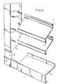
- Fig. 3 shows an alternative embodiment whereby the pin-like abutment means are fixed beforehand to the edge profiles 2 so that the grid blade profiles 4 can be pushed onto them.
- the pins can be of random type and can for instance be welded, riveted, integrally cast etc. onto the outer wall of the edge strip 2.
- the profile strip 4 can be manufactured from plate material whereby the edge strips are curled, whereby a slightly resilient effect can be exerted on the pin-like abutments 15.
Landscapes
- Engineering & Computer Science (AREA)
- Chemical & Material Sciences (AREA)
- Combustion & Propulsion (AREA)
- Mechanical Engineering (AREA)
- General Engineering & Computer Science (AREA)
- Air-Flow Control Members (AREA)
- Specific Sealing Or Ventilating Devices For Doors And Windows (AREA)
- Baking, Grill, Roasting (AREA)
- Duct Arrangements (AREA)
- Ventilation (AREA)
Priority Applications (1)
| Application Number | Priority Date | Filing Date | Title |
|---|---|---|---|
| AT89202489T ATE83551T1 (de) | 1988-10-03 | 1989-10-02 | Lueftungsgitter. |
Applications Claiming Priority (2)
| Application Number | Priority Date | Filing Date | Title |
|---|---|---|---|
| NL8802422A NL8802422A (nl) | 1988-10-03 | 1988-10-03 | Luchtrooster. |
| NL8802422 | 1988-10-03 |
Publications (2)
| Publication Number | Publication Date |
|---|---|
| EP0362957A1 true EP0362957A1 (de) | 1990-04-11 |
| EP0362957B1 EP0362957B1 (de) | 1992-12-16 |
Family
ID=19852987
Family Applications (1)
| Application Number | Title | Priority Date | Filing Date |
|---|---|---|---|
| EP89202489A Expired - Lifetime EP0362957B1 (de) | 1988-10-03 | 1989-10-02 | Lüftungsgitter |
Country Status (6)
| Country | Link |
|---|---|
| EP (1) | EP0362957B1 (de) |
| AT (1) | ATE83551T1 (de) |
| DE (1) | DE68903920T2 (de) |
| ES (1) | ES2036336T3 (de) |
| GR (1) | GR3006647T3 (de) |
| NL (1) | NL8802422A (de) |
Cited By (2)
| Publication number | Priority date | Publication date | Assignee | Title |
|---|---|---|---|---|
| WO1993012392A1 (de) * | 1991-12-13 | 1993-06-24 | Schako Metallwarenfabrik Ferdinand Schad Kg | Vorrichtung zum einbringen von zuluft und zum ausbringen von abluft |
| CN113665610A (zh) * | 2021-09-24 | 2021-11-19 | 安徽博格韦尔电气股份有限公司 | 一种列车翅片式排风组合格栅 |
Families Citing this family (2)
| Publication number | Priority date | Publication date | Assignee | Title |
|---|---|---|---|---|
| DE102009052896A1 (de) | 2009-11-13 | 2011-06-09 | Werner Patten | Bausystem für eine lüftungstechnische Vorrichtung |
| DE102020120066B4 (de) | 2020-07-29 | 2026-03-26 | Eitec Führungsbahnschutz-Systeme Gmbh | Luftführungsgitter |
Citations (3)
| Publication number | Priority date | Publication date | Assignee | Title |
|---|---|---|---|---|
| US3732800A (en) * | 1970-08-13 | 1973-05-15 | R Goettel | Ventilation louver grills |
| US3782050A (en) * | 1971-06-16 | 1974-01-01 | Dowco Corp | Louver assembly having improved weatherproofing and air flow characteristics |
| EP0227862A1 (de) * | 1985-09-05 | 1987-07-08 | Rachels Industries Inc. | Reibungsschlüssig gehaltene Luftleitlamellen |
-
1988
- 1988-10-03 NL NL8802422A patent/NL8802422A/nl not_active Application Discontinuation
-
1989
- 1989-10-02 ES ES198989202489T patent/ES2036336T3/es not_active Expired - Lifetime
- 1989-10-02 DE DE8989202489T patent/DE68903920T2/de not_active Expired - Fee Related
- 1989-10-02 EP EP89202489A patent/EP0362957B1/de not_active Expired - Lifetime
- 1989-10-02 AT AT89202489T patent/ATE83551T1/de not_active IP Right Cessation
-
1992
- 1992-12-23 GR GR920403097T patent/GR3006647T3/el unknown
Patent Citations (3)
| Publication number | Priority date | Publication date | Assignee | Title |
|---|---|---|---|---|
| US3732800A (en) * | 1970-08-13 | 1973-05-15 | R Goettel | Ventilation louver grills |
| US3782050A (en) * | 1971-06-16 | 1974-01-01 | Dowco Corp | Louver assembly having improved weatherproofing and air flow characteristics |
| EP0227862A1 (de) * | 1985-09-05 | 1987-07-08 | Rachels Industries Inc. | Reibungsschlüssig gehaltene Luftleitlamellen |
Cited By (2)
| Publication number | Priority date | Publication date | Assignee | Title |
|---|---|---|---|---|
| WO1993012392A1 (de) * | 1991-12-13 | 1993-06-24 | Schako Metallwarenfabrik Ferdinand Schad Kg | Vorrichtung zum einbringen von zuluft und zum ausbringen von abluft |
| CN113665610A (zh) * | 2021-09-24 | 2021-11-19 | 安徽博格韦尔电气股份有限公司 | 一种列车翅片式排风组合格栅 |
Also Published As
| Publication number | Publication date |
|---|---|
| ATE83551T1 (de) | 1993-01-15 |
| EP0362957B1 (de) | 1992-12-16 |
| DE68903920D1 (de) | 1993-01-28 |
| GR3006647T3 (de) | 1993-06-30 |
| ES2036336T3 (es) | 1993-05-16 |
| NL8802422A (nl) | 1990-05-01 |
| DE68903920T2 (de) | 1993-04-22 |
Similar Documents
| Publication | Publication Date | Title |
|---|---|---|
| CA1068866A (en) | Rafter vent | |
| US5046294A (en) | Perimeter clip | |
| US4621570A (en) | Louver assembly | |
| CA1274112A (en) | Air vent | |
| US4592271A (en) | Louvered vent | |
| US3911639A (en) | Method of making and installing a ventillating air distribution channel | |
| US4545165A (en) | Modular monolithic ceiling grid system | |
| US5950384A (en) | Louvered vent | |
| US7070497B2 (en) | Diffuser for central air conditioning system | |
| US6135878A (en) | Modular core air diffusers | |
| CA1209770A (en) | Openwork screen assembly | |
| EP0362957A1 (de) | Lüftungsgitter | |
| US3017973A (en) | Louvre and hanger therefor | |
| US2587509A (en) | Louver | |
| US4089257A (en) | Ventilation grille or grating | |
| US5718094A (en) | Supply air register construction | |
| US4446667A (en) | Damper frame construction | |
| US3643584A (en) | Readily assembled ventilator housing | |
| GB2051343A (en) | Louvred ventilators | |
| US2285984A (en) | Directional grille | |
| JPS6246118Y2 (de) | ||
| RU240168U1 (ru) | Узел соединения строительного маяка и корпуса решетки систем отопления, вентиляции и кондиционирования | |
| US4672890A (en) | Lightweight load bearing register | |
| AU721658B2 (en) | A louvre for a vent | |
| JPH07229257A (ja) | 家屋用換気装置の通気部構造 |
Legal Events
| Date | Code | Title | Description |
|---|---|---|---|
| PUAI | Public reference made under article 153(3) epc to a published international application that has entered the european phase |
Free format text: ORIGINAL CODE: 0009012 |
|
| AK | Designated contracting states |
Kind code of ref document: A1 Designated state(s): AT BE CH DE ES FR GB GR IT LI LU NL SE |
|
| 17P | Request for examination filed |
Effective date: 19900710 |
|
| 17Q | First examination report despatched |
Effective date: 19910115 |
|
| GRAA | (expected) grant |
Free format text: ORIGINAL CODE: 0009210 |
|
| AK | Designated contracting states |
Kind code of ref document: B1 Designated state(s): AT BE CH DE ES FR GB GR IT LI LU NL SE |
|
| REF | Corresponds to: |
Ref document number: 83551 Country of ref document: AT Date of ref document: 19930115 Kind code of ref document: T |
|
| ET | Fr: translation filed | ||
| REF | Corresponds to: |
Ref document number: 68903920 Country of ref document: DE Date of ref document: 19930128 |
|
| ITF | It: translation for a ep patent filed | ||
| REG | Reference to a national code |
Ref country code: ES Ref legal event code: FG2A Ref document number: 2036336 Country of ref document: ES Kind code of ref document: T3 |
|
| REG | Reference to a national code |
Ref country code: GR Ref legal event code: FG4A Free format text: 3006647 |
|
| PLBE | No opposition filed within time limit |
Free format text: ORIGINAL CODE: 0009261 |
|
| STAA | Information on the status of an ep patent application or granted ep patent |
Free format text: STATUS: NO OPPOSITION FILED WITHIN TIME LIMIT |
|
| 26N | No opposition filed | ||
| EPTA | Lu: last paid annual fee | ||
| EAL | Se: european patent in force in sweden |
Ref document number: 89202489.4 |
|
| PGFP | Annual fee paid to national office [announced via postgrant information from national office to epo] |
Ref country code: LU Payment date: 19971028 Year of fee payment: 9 |
|
| PGFP | Annual fee paid to national office [announced via postgrant information from national office to epo] |
Ref country code: GR Payment date: 19971029 Year of fee payment: 9 |
|
| PG25 | Lapsed in a contracting state [announced via postgrant information from national office to epo] |
Ref country code: LU Free format text: LAPSE BECAUSE OF NON-PAYMENT OF DUE FEES Effective date: 19981002 |
|
| PG25 | Lapsed in a contracting state [announced via postgrant information from national office to epo] |
Ref country code: GR Free format text: LAPSE BECAUSE OF NON-PAYMENT OF DUE FEES Effective date: 19981031 |
|
| PGFP | Annual fee paid to national office [announced via postgrant information from national office to epo] |
Ref country code: AT Payment date: 20001030 Year of fee payment: 12 Ref country code: SE Payment date: 20001030 Year of fee payment: 12 |
|
| PGFP | Annual fee paid to national office [announced via postgrant information from national office to epo] |
Ref country code: ES Payment date: 20001031 Year of fee payment: 12 |
|
| PGFP | Annual fee paid to national office [announced via postgrant information from national office to epo] |
Ref country code: CH Payment date: 20001103 Year of fee payment: 12 |
|
| PG25 | Lapsed in a contracting state [announced via postgrant information from national office to epo] |
Ref country code: AT Free format text: LAPSE BECAUSE OF NON-PAYMENT OF DUE FEES Effective date: 20011002 |
|
| PG25 | Lapsed in a contracting state [announced via postgrant information from national office to epo] |
Ref country code: SE Free format text: LAPSE BECAUSE OF NON-PAYMENT OF DUE FEES Effective date: 20011003 Ref country code: ES Free format text: LAPSE BECAUSE OF NON-PAYMENT OF DUE FEES Effective date: 20011003 |
|
| PG25 | Lapsed in a contracting state [announced via postgrant information from national office to epo] |
Ref country code: LI Free format text: LAPSE BECAUSE OF NON-PAYMENT OF DUE FEES Effective date: 20011031 Ref country code: CH Free format text: LAPSE BECAUSE OF NON-PAYMENT OF DUE FEES Effective date: 20011031 |
|
| REG | Reference to a national code |
Ref country code: GB Ref legal event code: IF02 |
|
| EUG | Se: european patent has lapsed |
Ref document number: 89202489.4 |
|
| REG | Reference to a national code |
Ref country code: CH Ref legal event code: PL |
|
| REG | Reference to a national code |
Ref country code: ES Ref legal event code: FD2A Effective date: 20021113 |
|
| PGFP | Annual fee paid to national office [announced via postgrant information from national office to epo] |
Ref country code: GB Payment date: 20050930 Year of fee payment: 17 |
|
| PG25 | Lapsed in a contracting state [announced via postgrant information from national office to epo] |
Ref country code: IT Free format text: LAPSE BECAUSE OF NON-PAYMENT OF DUE FEES;WARNING: LAPSES OF ITALIAN PATENTS WITH EFFECTIVE DATE BEFORE 2007 MAY HAVE OCCURRED AT ANY TIME BEFORE 2007. THE CORRECT EFFECTIVE DATE MAY BE DIFFERENT FROM THE ONE RECORDED. Effective date: 20051002 |
|
| PGFP | Annual fee paid to national office [announced via postgrant information from national office to epo] |
Ref country code: FR Payment date: 20051027 Year of fee payment: 17 |
|
| PGFP | Annual fee paid to national office [announced via postgrant information from national office to epo] |
Ref country code: NL Payment date: 20051031 Year of fee payment: 17 Ref country code: DE Payment date: 20051031 Year of fee payment: 17 |
|
| PGFP | Annual fee paid to national office [announced via postgrant information from national office to epo] |
Ref country code: BE Payment date: 20051103 Year of fee payment: 17 |
|
| PG25 | Lapsed in a contracting state [announced via postgrant information from national office to epo] |
Ref country code: NL Free format text: LAPSE BECAUSE OF NON-PAYMENT OF DUE FEES Effective date: 20070501 Ref country code: DE Free format text: LAPSE BECAUSE OF NON-PAYMENT OF DUE FEES Effective date: 20070501 |
|
| GBPC | Gb: european patent ceased through non-payment of renewal fee |
Effective date: 20061002 |
|
| NLV4 | Nl: lapsed or anulled due to non-payment of the annual fee |
Effective date: 20070501 |
|
| REG | Reference to a national code |
Ref country code: FR Ref legal event code: ST Effective date: 20070629 |
|
| PG25 | Lapsed in a contracting state [announced via postgrant information from national office to epo] |
Ref country code: GB Free format text: LAPSE BECAUSE OF NON-PAYMENT OF DUE FEES Effective date: 20061002 |
|
| BERE | Be: lapsed |
Owner name: *DE WAAL CASPARUS WILHELMUS Effective date: 20061031 |
|
| PG25 | Lapsed in a contracting state [announced via postgrant information from national office to epo] |
Ref country code: FR Free format text: LAPSE BECAUSE OF NON-PAYMENT OF DUE FEES Effective date: 20061031 |
|
| PG25 | Lapsed in a contracting state [announced via postgrant information from national office to epo] |
Ref country code: BE Free format text: LAPSE BECAUSE OF FAILURE TO SUBMIT A TRANSLATION OF THE DESCRIPTION OR TO PAY THE FEE WITHIN THE PRESCRIBED TIME-LIMIT Effective date: 20061031 |