EP0362958A1 - Luftvorhanggerät - Google Patents
Luftvorhanggerät Download PDFInfo
- Publication number
- EP0362958A1 EP0362958A1 EP89202490A EP89202490A EP0362958A1 EP 0362958 A1 EP0362958 A1 EP 0362958A1 EP 89202490 A EP89202490 A EP 89202490A EP 89202490 A EP89202490 A EP 89202490A EP 0362958 A1 EP0362958 A1 EP 0362958A1
- Authority
- EP
- European Patent Office
- Prior art keywords
- air
- opening
- outflow
- housing
- guide elements
- Prior art date
- Legal status (The legal status is an assumption and is not a legal conclusion. Google has not performed a legal analysis and makes no representation as to the accuracy of the status listed.)
- Granted
Links
- 229910052729 chemical element Inorganic materials 0.000 claims 1
- 230000008901 benefit Effects 0.000 description 4
- 230000002349 favourable effect Effects 0.000 description 4
- 238000010276 construction Methods 0.000 description 2
- 230000000694 effects Effects 0.000 description 2
- 238000000926 separation method Methods 0.000 description 2
- 241000237858 Gastropoda Species 0.000 description 1
- 229940000425 combination drug Drugs 0.000 description 1
- 238000013016 damping Methods 0.000 description 1
- 238000009499 grossing Methods 0.000 description 1
- 230000007246 mechanism Effects 0.000 description 1
- 210000002105 tongue Anatomy 0.000 description 1
- 238000009423 ventilation Methods 0.000 description 1
Images
Classifications
-
- F—MECHANICAL ENGINEERING; LIGHTING; HEATING; WEAPONS; BLASTING
- F24—HEATING; RANGES; VENTILATING
- F24F—AIR-CONDITIONING; AIR-HUMIDIFICATION; VENTILATION; USE OF AIR CURRENTS FOR SCREENING
- F24F13/00—Details common to, or for air-conditioning, air-humidification, ventilation or use of air currents for screening
- F24F13/02—Ducting arrangements
- F24F13/06—Outlets for directing or distributing air into rooms or spaces, e.g. ceiling air diffuser
- F24F13/075—Outlets for directing or distributing air into rooms or spaces, e.g. ceiling air diffuser having parallel rods or lamellae directing the outflow, e.g. the rods or lamellae being individually adjustable
-
- F—MECHANICAL ENGINEERING; LIGHTING; HEATING; WEAPONS; BLASTING
- F24—HEATING; RANGES; VENTILATING
- F24F—AIR-CONDITIONING; AIR-HUMIDIFICATION; VENTILATION; USE OF AIR CURRENTS FOR SCREENING
- F24F9/00—Use of air currents for screening, e.g. air curtains
Definitions
- the invention relates to an air curtain device as described in the heading of claim 1.
- Such devices are usually used in the passage openings of buildings, for instance shops and department stores.
- the air curtain generated by the device at the location of the passage opening is intended to maintain a separation between the climate in the building and the climate outside it. Due to the air curtain it is possible to have a visually completely free passage opening, without the energy loss resulting from the escape of for instance heated or cooled air from the building assuming inadmissible proportions.
- the air flowing out of the air outflow opening of the device is itself usually heated or cooled. Since at least some air escapes from a building, for instance through gaps and ventilation openings, air from outside the building will flow inside at the location of the passage opening into the building. This air is hereby mixed with the air of the air curtain, so that this is brought to the desired temperature. In this way a considerable portion of the energy used to bring the air in the air curtain to the desired temperature is to the benefit of the interior climate of the building.
- the invention now has for its object to reduce the energy loss with an air curtain device of the type described in the preamble.
- a practical embodiment of the air curtain device according to the invention is characterized in claim 2.
- the lengthwise dimension is equal to or less than the transverse dimension, there occurs rather an amplifying than a lessening of turbulence.
- step of claim 3 is preferably applied.
- step of claim 4 is achieved that the average speed in the outflow direction remains the same, which contributes to damping of the air eddying.
- a very favourable embodiment is characterized in claim 5. It has been found that this embodiment has a very favourable effect on the air eddyings, while moreover the flow resistance is limited.
- a further advantage of this embodiment occurs in combination with the characterizing steps of claim 6. Since in the lengthwise direction the fans have outlet openings lying at a mutual distance, the air supply at the height of the fans is not uniform. It is now been found with the strip-like guide elements that the unevenly supplied air leaves the guide elements as a very considerably more uniform, flat stream of air. It is thus hereby possible to choose fans which in view of the required supply and the occurring pressure differences have a maximum output. The fact that thereby the air does not leave the fans uniformly as seen in the lengthwise direction of the device is of less importance in this embodiment. Because the optimal fans can be chosen an energy saving can in this manner likewise be achieved.
- the air supply per unit of length of the air outflow opening becomes still more uniform.
- the flat stream of air is then also virtually completely continuous in lengthwise direction.
- the level of turbulence is hereby further reduced in a favourable manner.
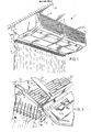
- the air curtain device 1 shown in fig. 1 is mounted in a manner to be further described above a passage opening in a building 2.
- This passage opening can be the entrance or a connecting opening between two areas of the building.
- the device 1 comprises a housing 3 which is provided with an elongate air outflow opening 6.
- Air supply means which in the embodiment shown and described here are formed by fans accommodated in the housing 3 of the device 1, are connected to the air outflow opening 6.
- the air is drawn in through inlet grids 5, which are formed in covers 4 closing off the housing 3.
- elements 7 Arranged in the outflow opening 6 are elements 7 which reduce the turbulence of the blown out air.
- the flat stream of air 8 leaving the opening 6 penetrates to the bottom of the passage opening and thus forms in further per se known manner a separation between the two climates on either side of the air curtain 8.
- Fig. 2 shows in more detail the construction of the air curtain device 1.
- the housing 3 of the device 1 is suspended from a horizontal ceiling surface by means of mounting strips 10, which are themselves screwed fixedly into the ceiling of the building 2 and are bent over at their ends into hooks 11 in the manner shown in the drawing.
- two channels 12 are formed, on one upper edge of which an inwardly protruding edge 13 of plate material is formed.
- the device can simply be suspended on the hooks 11 thereof by manipulating the device 1 such that the hooks 11 are placed into the channels 12 and come to fall behind the edges 13.
- the final position can be fixed using locking screws 14.
- This fitting with mounting strips 10 has the advantage that the mounting position of the device is to a large degree independent of the bearing construction in the ceiling.
- the strips can be simply attached in the suitable positions in their lengthwise direction to the bearing parts.
- Air filter elements 15 are arranged in the housing 3 of the device 1 behind the inlet grids 5. These filter elements 15 can be changed and are accessible through downward swivelling of the covers 4.
- the air supply means are, as previously noted, formed by a number of fans 16.
- a heat exchanger 23 Arranged in the housing 3 between the air filters 15 and the fans 16 is a heat exchanger 23. The indrawn air is heated or cooled in this heat exchanger in accordance with the desired use.
- Each fan 16 comprises an electric motor 17, which drives a rotor 18.
- the fan housing 19 formed as a so-called snail shell extends around the rotor.
- the fan 16 is mounted with the housing 19 on a mounting plate 27 of the housing 3. Openings 20 corresponding with the fans are arranged in this plate.
- the fans 16 applied here are radial fans with suction openings on either side of the fan housing 19. Fans of this type have a favourable output for the conditions intended here.
- dividing plates 21 Connecting onto the outlet openings 20 of the fans are dividing plates 21 which extend up to the turbulence reducing elements at the location of the outflow opening 6.
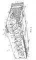
- these elements are formed by guide elements 22 which are formed by strip-like elements extending in the lengthwise direction of the air outflow opening 6 and parallel to each other.
- the distance between the strip-like guide elements is smaller than or equal to approximately one fifth of the height of these strip-like elements 22.
- the guide elements provide in the first instance the effect intended by the invention of reducing the degree of turbulence in the outflowing air.
- these moreover ensure a smoothing out of the flow irregularities in the air leaving the fans, in the lengthwise direction of the outflow opening 6. So that although the air from the discrete outlet openings 20 of the fans 19 is fed to the guide elements from varying directions, an adjustment occurs such that the flat stream of air leaving the guide elements 22 has a great extent of uniformity in lengthwise direction.
- the embodiment in fig. 3 is distinguished in characteristic manner in that the guide elements 22 are assembled with a number of comb shaped supports 33 into a unit 30 which is mounted pivotally on an axis 31 in the housing 3.
- the strip-like slats 22 are joined to the unit 30 by bolts extending through these and through each of the comb shaped supports 33.
- the supports 33 are connected pivotally to the housing 3 using forks 32.
- the unit 30 can be swivelled in the manner indicated out of the drawn position, in which the stream of air is directed slightly slanting outward, to the position indicated by the dashed line, in which the stream of air is directed vertically downward.
- the guide elements 22 are adjusted such that optimal flow conditions are created. When for instance a relatively lower pressure can occur inside the building than outside the building, which will usually have the consequence that the air curtain bends inward, the stream of air can initially be directed slightly outward.
- Fig. 3 shows further the way in which the cover 4 grips onto the housing 3.
- the cover 4 is provided with a number of slot shaped openings 26 which drop over tongues 25 arranged on the housing 3.
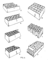
- Fig. 4 shows a selected number of possible different embodiments of the guide elements according to the invention. Characteristic for each of these embodiments is that outflow channels are defined which have in the general outflow direction, which is vertical in the examples shown, a lengthwise dimension which is a number of times greater than the smallest dimension transversely of this direction. As noted earlier this lengthwise dimension is preferably at least five times as great as the transverse dimension.
- the degree of turbulence of the outflowing air is reduced by these guide elements such that the interface with the outside air remains relatively “smooth", so that a minimum of mixing and diverting of the air of the air curtain to the outside takes place, while moreover the widening of the stream of air as the distance to the outflow opening increases is greatly limited, so that the flat stream of air extends further downward than when the degree of turbulence of the air is high.
- the device according to the invention does not necessarily need to have integrated air supply means.
- the invention can be applied just as well with an air curtain device wherein the air supply means are external.
- Other embodiments also fall within the scope of the annexed claims.
Landscapes
- Engineering & Computer Science (AREA)
- Chemical & Material Sciences (AREA)
- Combustion & Propulsion (AREA)
- Mechanical Engineering (AREA)
- General Engineering & Computer Science (AREA)
- Air-Conditioning Room Units, And Self-Contained Units In General (AREA)
- Tents Or Canopies (AREA)
- Chair Legs, Seat Parts, And Backrests (AREA)
- Air-Flow Control Members (AREA)
- Curtains And Furnishings For Windows Or Doors (AREA)
- Ventilation (AREA)
Priority Applications (1)
| Application Number | Priority Date | Filing Date | Title |
|---|---|---|---|
| AT89202490T ATE88805T1 (de) | 1988-10-04 | 1989-10-02 | Luftvorhanggeraet. |
Applications Claiming Priority (2)
| Application Number | Priority Date | Filing Date | Title |
|---|---|---|---|
| NL8802430 | 1988-10-04 | ||
| NL8802430A NL8802430A (nl) | 1988-10-04 | 1988-10-04 | Luchtgordijn-inrichting. |
Publications (2)
| Publication Number | Publication Date |
|---|---|
| EP0362958A1 true EP0362958A1 (de) | 1990-04-11 |
| EP0362958B1 EP0362958B1 (de) | 1993-04-28 |
Family
ID=19852991
Family Applications (1)
| Application Number | Title | Priority Date | Filing Date |
|---|---|---|---|
| EP89202490A Expired - Lifetime EP0362958B1 (de) | 1988-10-04 | 1989-10-02 | Luftvorhanggerät |
Country Status (5)
| Country | Link |
|---|---|
| EP (1) | EP0362958B1 (de) |
| AT (1) | ATE88805T1 (de) |
| DE (1) | DE68906230T2 (de) |
| ES (1) | ES2040983T3 (de) |
| NL (1) | NL8802430A (de) |
Cited By (9)
| Publication number | Priority date | Publication date | Assignee | Title |
|---|---|---|---|---|
| EP0762094A1 (de) * | 1995-09-07 | 1997-03-12 | The Perkin-Elmer Corporation | Trockengasvorhang für kryogenische Oberfläche |
| FR2740205A1 (fr) * | 1995-10-23 | 1997-04-25 | Unir Ultra Propre Nutrition In | Dispositif de protection contre l'aerocontamination |
| EP1054219A1 (de) * | 1999-05-21 | 2000-11-22 | Jeven Oy | Verfahren und Vorrichtung zur Lüftung |
| DE10017019C1 (de) * | 2000-04-05 | 2001-07-05 | Lks Israel Gmbh Klimatechnisch | Schlitzauslass für Luftschleier-Anlagen |
| NL1031200C2 (nl) * | 2006-02-21 | 2007-08-22 | Biddle B V | Uitblaasrooster en een luchtgordijn-inrichting. |
| DE102008050546A1 (de) * | 2008-10-06 | 2010-04-15 | Airbus Deutschland Gmbh | Side-Feeder-Luftführungselement für eine Flugzeugklimaanlage |
| US20100184365A1 (en) * | 2009-01-21 | 2010-07-22 | Flowair Glogowski I Brzezinski Sp.J. | Air curtain with a main air stream and an auxiliary air stream, and a device and method for producing the same |
| EP3369597A1 (de) * | 2017-03-01 | 2018-09-05 | H.Opdam Management B.V. | Luftvorhang und fahrzeug mit einem luftvorhang |
| US11015824B2 (en) | 2016-09-02 | 2021-05-25 | Inertechip Llc | Air curtain containment system and assembly for data centers |
Families Citing this family (5)
| Publication number | Priority date | Publication date | Assignee | Title |
|---|---|---|---|---|
| ATE122138T1 (de) * | 1992-02-05 | 1995-05-15 | Luftschleieranlagen Gmbh | Luftschleieranlage. |
| DE10142502A1 (de) | 2001-08-30 | 2003-03-20 | Bsh Bosch Siemens Hausgeraete | Fruchtpresse |
| DE102004001765A1 (de) * | 2004-01-12 | 2005-08-04 | Jochen Schanze | Luftschleieranlage |
| DE102014114491B3 (de) * | 2014-10-07 | 2015-10-01 | Arwus Gmbh | Schlitzauslass für Luftschott-Anlagen mit Strömungsumlenkung |
| DE102016116832A1 (de) | 2016-09-08 | 2018-03-08 | Arwus Gmbh | Schlitzauslass für Luftschott-Anlagen |
Citations (7)
| Publication number | Priority date | Publication date | Assignee | Title |
|---|---|---|---|---|
| US2057494A (en) * | 1936-05-18 | 1936-10-13 | Hart & Cooley Mfg Company | Adjustable directional grille |
| US3229609A (en) * | 1964-01-15 | 1966-01-18 | Nat Ind Equipment Co | Multiple air screen for use with a doorway |
| US3291027A (en) * | 1965-02-10 | 1966-12-13 | Dual Jet Refrigeration Co | Air outlet nozzles for an air curtain device |
| US3327935A (en) * | 1965-08-31 | 1967-06-27 | Sigmund F Berlant | Air curtain |
| US3332334A (en) * | 1965-08-09 | 1967-07-25 | Melzer Herman | Air curtain apparatus |
| US3362469A (en) * | 1966-01-03 | 1968-01-09 | Berner Ind Inc | Air curtain |
| DE8716517U1 (de) * | 1987-12-15 | 1988-02-11 | Löbig, Rolf, 5653 Leichlingen | Vorrichtung zum Erzeugen eines Luftschleiers od. dgl. |
-
1988
- 1988-10-04 NL NL8802430A patent/NL8802430A/nl not_active Application Discontinuation
-
1989
- 1989-10-02 AT AT89202490T patent/ATE88805T1/de not_active IP Right Cessation
- 1989-10-02 ES ES198989202490T patent/ES2040983T3/es not_active Expired - Lifetime
- 1989-10-02 EP EP89202490A patent/EP0362958B1/de not_active Expired - Lifetime
- 1989-10-02 DE DE8989202490T patent/DE68906230T2/de not_active Expired - Lifetime
Patent Citations (7)
| Publication number | Priority date | Publication date | Assignee | Title |
|---|---|---|---|---|
| US2057494A (en) * | 1936-05-18 | 1936-10-13 | Hart & Cooley Mfg Company | Adjustable directional grille |
| US3229609A (en) * | 1964-01-15 | 1966-01-18 | Nat Ind Equipment Co | Multiple air screen for use with a doorway |
| US3291027A (en) * | 1965-02-10 | 1966-12-13 | Dual Jet Refrigeration Co | Air outlet nozzles for an air curtain device |
| US3332334A (en) * | 1965-08-09 | 1967-07-25 | Melzer Herman | Air curtain apparatus |
| US3327935A (en) * | 1965-08-31 | 1967-06-27 | Sigmund F Berlant | Air curtain |
| US3362469A (en) * | 1966-01-03 | 1968-01-09 | Berner Ind Inc | Air curtain |
| DE8716517U1 (de) * | 1987-12-15 | 1988-02-11 | Löbig, Rolf, 5653 Leichlingen | Vorrichtung zum Erzeugen eines Luftschleiers od. dgl. |
Non-Patent Citations (2)
| Title |
|---|
| PATENT ABSTRACTS OF JAPAN, vol. 1, no. 137, 11th November 1977, page 4774 M 77; & JP-A-52 78 152 (FUJI DENKI SEIZO K.K.) 01-07-1977 * |
| PATENT ABSTRACTS OF JAPAN, vol. 1, no. 22, 25th March 1977, page 1631 M 76; & JP-A-51 134 462 (SANYO DENKI K.K.) 20-11-1976 * |
Cited By (14)
| Publication number | Priority date | Publication date | Assignee | Title |
|---|---|---|---|---|
| EP0762094A1 (de) * | 1995-09-07 | 1997-03-12 | The Perkin-Elmer Corporation | Trockengasvorhang für kryogenische Oberfläche |
| FR2740205A1 (fr) * | 1995-10-23 | 1997-04-25 | Unir Ultra Propre Nutrition In | Dispositif de protection contre l'aerocontamination |
| EP1054219A1 (de) * | 1999-05-21 | 2000-11-22 | Jeven Oy | Verfahren und Vorrichtung zur Lüftung |
| DE10017019C1 (de) * | 2000-04-05 | 2001-07-05 | Lks Israel Gmbh Klimatechnisch | Schlitzauslass für Luftschleier-Anlagen |
| NL1031200C2 (nl) * | 2006-02-21 | 2007-08-22 | Biddle B V | Uitblaasrooster en een luchtgordijn-inrichting. |
| WO2007097618A1 (en) * | 2006-02-21 | 2007-08-30 | Biddle B.V. | Blow-out grid and an air curtain device |
| DE102008050546A1 (de) * | 2008-10-06 | 2010-04-15 | Airbus Deutschland Gmbh | Side-Feeder-Luftführungselement für eine Flugzeugklimaanlage |
| DE102008050546B4 (de) * | 2008-10-06 | 2012-03-08 | Airbus Operations Gmbh | Side-Feeder-Luftführungselement für eine Flugzeugklimaanlage |
| US9067678B2 (en) | 2008-10-06 | 2015-06-30 | Airbus Operations Gmbh | Side feeder air guiding element for an aircraft air-conditioning system |
| US20100184365A1 (en) * | 2009-01-21 | 2010-07-22 | Flowair Glogowski I Brzezinski Sp.J. | Air curtain with a main air stream and an auxiliary air stream, and a device and method for producing the same |
| US11015824B2 (en) | 2016-09-02 | 2021-05-25 | Inertechip Llc | Air curtain containment system and assembly for data centers |
| US11927363B2 (en) | 2016-09-02 | 2024-03-12 | Inertech Ip Llc | Air curtain containment system and assembly for data centers |
| EP3369597A1 (de) * | 2017-03-01 | 2018-09-05 | H.Opdam Management B.V. | Luftvorhang und fahrzeug mit einem luftvorhang |
| NL2018444B1 (en) * | 2017-03-01 | 2018-09-19 | H Opdam Man B V | An air curtain, and a vehicle comprising an air curtain |
Also Published As
| Publication number | Publication date |
|---|---|
| EP0362958B1 (de) | 1993-04-28 |
| DE68906230T2 (de) | 1993-08-12 |
| ATE88805T1 (de) | 1993-05-15 |
| NL8802430A (nl) | 1990-05-01 |
| DE68906230D1 (de) | 1993-06-03 |
| ES2040983T3 (es) | 1993-11-01 |
Similar Documents
| Publication | Publication Date | Title |
|---|---|---|
| EP0362958B1 (de) | Luftvorhanggerät | |
| KR102257588B1 (ko) | 환기구용 디퓨저 필터장치 | |
| EP0230098B1 (de) | Luftauslassvorrichtung für Klimaanlagen | |
| US4730551A (en) | Heat distributor for suspended ceilings | |
| US5107687A (en) | Air conditioning system | |
| KR102514029B1 (ko) | 공기가 통과하는 행거부 및 이를 포함하는 천장 조립체 | |
| KR102927990B1 (ko) | 가변 냉매 패키지 | |
| EP0528696B1 (de) | Paneel mit gerichtetem Luftauslass für Reinraumlüftungssysteme | |
| US4043256A (en) | Animal enclosure with pressure controlled ventilation inlet and deflection means | |
| US5251608A (en) | Air canopy ventilation system | |
| US5713346A (en) | Apparatus and method for removing fumes from the space above a cooking appliance | |
| US6041772A (en) | Overhead ventilation system incorporating a fixed blade diffuser with opposed pivoting blades for use with a cooking appliance | |
| US4445426A (en) | Slanted housing fan enclosure | |
| CA2278538A1 (en) | Bath ventilating, heating and air conditioning unit | |
| US6422935B1 (en) | Air vent covering assembly | |
| RU2708105C1 (ru) | Компактная система приточной вентиляции (устройство в целом), устройство для принудительной подачи воздуха и вентиляционная решетка (самостоятельные части устройства) | |
| US4586486A (en) | Multilevel air distribution panel for air ventilation hood | |
| US6159093A (en) | Powered exhaust fan | |
| DE202007001644U1 (de) | Modular aufgebaute Lüftungseinrichtung für den Einsatz im Reinraum | |
| KR100209035B1 (ko) | 팬 배출 덕트용 루우버 조립체 | |
| EP1188992A2 (de) | Luftbehandlung und Belüftungsvorrichtung | |
| US3673946A (en) | Air diffuser | |
| US4250870A (en) | Apparatus and method for removing fumes from the space above a cooking appliance in a restaurant | |
| US12510268B2 (en) | Dual inlet air diffuser | |
| US4869157A (en) | Modular air bar |
Legal Events
| Date | Code | Title | Description |
|---|---|---|---|
| PUAI | Public reference made under article 153(3) epc to a published international application that has entered the european phase |
Free format text: ORIGINAL CODE: 0009012 |
|
| AK | Designated contracting states |
Kind code of ref document: A1 Designated state(s): AT BE CH DE ES FR GB GR IT LI LU NL SE |
|
| 17P | Request for examination filed |
Effective date: 19900518 |
|
| 17Q | First examination report despatched |
Effective date: 19910510 |
|
| ITF | It: translation for a ep patent filed | ||
| GRAA | (expected) grant |
Free format text: ORIGINAL CODE: 0009210 |
|
| AK | Designated contracting states |
Kind code of ref document: B1 Designated state(s): AT BE CH DE ES FR GB GR IT LI LU NL SE |
|
| REF | Corresponds to: |
Ref document number: 88805 Country of ref document: AT Date of ref document: 19930515 Kind code of ref document: T |
|
| REF | Corresponds to: |
Ref document number: 68906230 Country of ref document: DE Date of ref document: 19930603 |
|
| ET | Fr: translation filed | ||
| REG | Reference to a national code |
Ref country code: GR Ref legal event code: FG4A Free format text: 3008432 |
|
| REG | Reference to a national code |
Ref country code: ES Ref legal event code: FG2A Ref document number: 2040983 Country of ref document: ES Kind code of ref document: T3 |
|
| EPTA | Lu: last paid annual fee | ||
| PLBE | No opposition filed within time limit |
Free format text: ORIGINAL CODE: 0009261 |
|
| STAA | Information on the status of an ep patent application or granted ep patent |
Free format text: STATUS: NO OPPOSITION FILED WITHIN TIME LIMIT |
|
| 26N | No opposition filed | ||
| EAL | Se: european patent in force in sweden |
Ref document number: 89202490.2 |
|
| REG | Reference to a national code |
Ref country code: GB Ref legal event code: IF02 |
|
| PGFP | Annual fee paid to national office [announced via postgrant information from national office to epo] |
Ref country code: LU Payment date: 20031030 Year of fee payment: 15 |
|
| PGFP | Annual fee paid to national office [announced via postgrant information from national office to epo] |
Ref country code: GR Payment date: 20031031 Year of fee payment: 15 |
|
| PG25 | Lapsed in a contracting state [announced via postgrant information from national office to epo] |
Ref country code: LU Free format text: LAPSE BECAUSE OF NON-PAYMENT OF DUE FEES Effective date: 20041002 |
|
| PG25 | Lapsed in a contracting state [announced via postgrant information from national office to epo] |
Ref country code: GR Free format text: LAPSE BECAUSE OF NON-PAYMENT OF DUE FEES Effective date: 20050504 |
|
| PGFP | Annual fee paid to national office [announced via postgrant information from national office to epo] |
Ref country code: NL Payment date: 20081031 Year of fee payment: 20 |
|
| PGFP | Annual fee paid to national office [announced via postgrant information from national office to epo] |
Ref country code: CH Payment date: 20081030 Year of fee payment: 20 Ref country code: DE Payment date: 20081030 Year of fee payment: 20 |
|
| PGFP | Annual fee paid to national office [announced via postgrant information from national office to epo] |
Ref country code: ES Payment date: 20081031 Year of fee payment: 20 Ref country code: AT Payment date: 20081030 Year of fee payment: 20 |
|
| PGFP | Annual fee paid to national office [announced via postgrant information from national office to epo] |
Ref country code: IT Payment date: 20081030 Year of fee payment: 20 Ref country code: BE Payment date: 20081030 Year of fee payment: 20 Ref country code: SE Payment date: 20081031 Year of fee payment: 20 |
|
| PGFP | Annual fee paid to national office [announced via postgrant information from national office to epo] |
Ref country code: FR Payment date: 20081031 Year of fee payment: 20 |
|
| PGFP | Annual fee paid to national office [announced via postgrant information from national office to epo] |
Ref country code: GB Payment date: 20081105 Year of fee payment: 20 |
|
| REG | Reference to a national code |
Ref country code: CH Ref legal event code: PL |
|
| REG | Reference to a national code |
Ref country code: GB Ref legal event code: PE20 Expiry date: 20091001 |
|
| BE20 | Be: patent expired |
Owner name: F.H. *BIDDLE B.V. Effective date: 20091002 |
|
| PG25 | Lapsed in a contracting state [announced via postgrant information from national office to epo] |
Ref country code: GB Free format text: LAPSE BECAUSE OF EXPIRATION OF PROTECTION Effective date: 20091001 |
|
| NLV7 | Nl: ceased due to reaching the maximum lifetime of a patent | ||
| EUG | Se: european patent has lapsed | ||
| REG | Reference to a national code |
Ref country code: ES Ref legal event code: FD2A Effective date: 20091003 |
|
| PG25 | Lapsed in a contracting state [announced via postgrant information from national office to epo] |
Ref country code: ES Free format text: LAPSE BECAUSE OF EXPIRATION OF PROTECTION Effective date: 20091003 |
|
| PG25 | Lapsed in a contracting state [announced via postgrant information from national office to epo] |
Ref country code: NL Free format text: LAPSE BECAUSE OF EXPIRATION OF PROTECTION Effective date: 20091002 |