EP0363027A2 - Ringresonator-Gyroskop - Google Patents
Ringresonator-Gyroskop Download PDFInfo
- Publication number
- EP0363027A2 EP0363027A2 EP19890309288 EP89309288A EP0363027A2 EP 0363027 A2 EP0363027 A2 EP 0363027A2 EP 19890309288 EP19890309288 EP 19890309288 EP 89309288 A EP89309288 A EP 89309288A EP 0363027 A2 EP0363027 A2 EP 0363027A2
- Authority
- EP
- European Patent Office
- Prior art keywords
- frequency
- channel
- ccw
- signal
- gain
- Prior art date
- Legal status (The legal status is an assumption and is not a legal conclusion. Google has not performed a legal analysis and makes no representation as to the accuracy of the status listed.)
- Granted
Links
Images


Classifications
-
- G—PHYSICS
- G01—MEASURING; TESTING
- G01C—MEASURING DISTANCES, LEVELS OR BEARINGS; SURVEYING; NAVIGATION; GYROSCOPIC INSTRUMENTS; PHOTOGRAMMETRY OR VIDEOGRAMMETRY
- G01C19/00—Gyroscopes; Turn-sensitive devices using vibrating masses; Turn-sensitive devices without moving masses; Measuring angular rate using gyroscopic effects
- G01C19/58—Turn-sensitive devices without moving masses
- G01C19/64—Gyrometers using the Sagnac effect, i.e. rotation-induced shifts between counter-rotating electromagnetic beams
- G01C19/72—Gyrometers using the Sagnac effect, i.e. rotation-induced shifts between counter-rotating electromagnetic beams with counter-rotating light beams in a passive ring, e.g. fibre laser gyrometers
- G01C19/727—Gyrometers using the Sagnac effect, i.e. rotation-induced shifts between counter-rotating electromagnetic beams with counter-rotating light beams in a passive ring, e.g. fibre laser gyrometers using a passive ring resonator
Definitions
- the present invention relates to a ring resonator gyroscope.
- a ring resonator gyroscope is indicated generally at 10 and operates by inserting laser light into a resonator so as to form clockwise (CW) and counterclockwise (CCW) beams.
- the ring resonator gyroscope 10 comprises a fibre resonator 12 formed by connecting a length of optical fibre 14 back onto itself in a coupler 16 which has a high coupling ratio.
- a laser 18 produces a laser beam of narrow linewidth which is split at a beamsplitter 20 to allow insertion of light in both directions in the fibre resonator 12 and also to allow separate monitoring of the light in each direction.
- Acousto-optic deflectors 22 and 24 are placed in each path to allow the relative frequency of the CCW and CW beams respectively to be adjusted.
- the CW beam is deflected by a mirror 25 to the deflector 24.
- Microscope objectives 26 and 27 focus laser light onto the ends of the fibre 14.
- the output intensity is derived from the coherent addition of all of the combined delayed waves of varying amplitude and phase and depends on the coupling ratio of the coupler 16, the wavelength of the laser source and the delay time of the fibre resonator 12.
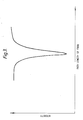
- Figure 3 shows the resonance characteristics of a fibre resonator. Changing the phase path of the fibre resonator by changing the length of the fibre resonator or the source wavelength will vary the resonance characteristic because of the consequent change in the relative phases of the combining waves. When the phase path is an integral number of wavelengths the resonance characteristic exhibits a null. The intensity inside the loop has an inverse function to that of the output. At resonance, zero output intensity, the wave continually recirculates within the loop, and is lost by scattering from the loop.
- FSR 'free spectral range'
- the spacing between modes is about 20 MHz, and if the finesse of the resonator is 100 the halfwidth of the resonance is 200KHz.
- the light impinging on the photodetector 30 is used to control the path length of the fibre resonator 12 to maintain resonance. This is achieved by causing an electrical control signal to be supplied to a cylindrical piezoelectric transducer (PZT) 34 around which the fibre 14 is wound and which is operable to stretch the fibre 14.
- PZT cylindrical piezoelectric transducer
- a frequency and path length control system is indicated generally at 40 and comprises: two low noise amplifiers 42 and 44 to which the photodetectors 30 and 32 respectively are connected; a differential amplifier 46 receiving the output of the amplifiers 42 and 44; an oscillator 48 operating at frequency Wc connected to two lock-in amplifiers 50 and 52 the inputs of which are connected to the outputs of the low noise amplifier 42 and the differential amplifier 46 respectively; two integrators 54 and 56 having inputs connected to the lock-in amplifiers 50 and 52 respectively; a high-voltage amplifier 58 having inputs connected to the oscillator 48 and integrator 54 and an output connected to the PZT 34; a voltage-to-frequency convertor 60 having an input connected to the integrator 56 and an output connected to the acousto-optic deflector 22.
- the difference in intensity of the CW and CCW beams sensed by the photodetectors 30 and 32 at frequency Wc is used as the error signal to drive the frequency of the acoustic optic deflector 24 to the minimum of the CW resonance.
- the path length is altered by applying a sinusoidal modulation on the PZT 34 at a frequency Wc (typically 10 kHz) via the high voltage amplifier 58. If the path length is not held accurately, there will be a signal on the photodetector 30 at frequency Wc, the sign of which determines which side of the resonance is the fibre length.
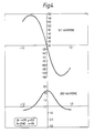
- Figure 4 shows the variation of the light intensity at frequencies Wc and 2wc as a function of detuning from line centre. The former goes through zero at line centre, and so can be used as an error signal to drive the path length to line centre.
- the arrangement shown in figure 2 achieves this by a synchronous detection scheme using the lock-in amplifier 50 with the reference signal at frequency Wc.
- Acousto-optic deflector 22 is held at a fixed frequency for the CCW beam.
- the light in the CW beam goes through acousto-optic deflector 24 which gives a variable frequency offset according to the output from the voltage-to-frequency convertor 60.
- a disadvantage of the arrangement shown in Figure 2 is that it only gives a small amount of common-mode rejection which depends upon the relative gains of the two low noise amplifiers 42 and 44. Also there may be slight differences in the intensities of light falling onto the two photodetectors 30 and 32 which will again reduce the effectiveness of this scheme to reduce common mode signal errors.
- a system for controlling the frequency of a light beam in a ring resonator gyroscope in which, in use, there are two beams, one travelling CW and the other travelling CCW comprising: a first channel comprising first detector means for receiving a portion of the CW beam and first amplifier means for amplifying a signal from the first detector means to form a CW signal; a second channel comprising second detector means for receiving a portion of the CCW beam and second amplifier means for amplifying a signal from the second detector means to form a CCW signal; and means for comparing the CW and CCW signals, characterised by gain control means for nulling the gain differences between the first and second channels.
- a system according to the present invention allows considerably more common mode rejection of any path length offset due to errors in the path length servo and therefore improves the performance of the ring resonator gyroscope.
- the gain control means is operable to control the gain of one of the first and second amplifier means.
- the system may comprise means for modulating the path length of the ring resonator gyroscope at a frequency Wc and means for comparing the relative intensities of signals at a frequency 2Wc in the CW and CCW beams and means for using the intensity difference to generate a gain control signal.
- the gain control means may comprise a dual channel filter in each of the first and second channels wherein each of the dual channel filters is operable to select signals at a frequency of 2Wc on one channel for use in gain control and to suppress signals at a frequency of 2Wc on the other channel to provide a signal for use in path length control.
- the gain control means comprises a differential amplifier for comparing the outputs of said one channels of the dual channel filters and which is connected to a lock-in amplifier referenced to 2Wc connected to resistive means for controlling the gain of one of the first and second channels.
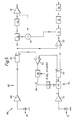
- the system 100 comprises first and second channels 102 and 104 for detecting the CW and CCW beams respectively and for producing CW and CCW signals and further comprises gain control means 106.
- the first channel 102 comprises the photodetector 30, a low noise amplifier 108 and a dual channel switched capacitor filter 110.
- the second channel 104 comprises the photodetector 32, a low noise amplifier 112 and a dual channel switched capacitor filter 114.
- the gain control means 106 is associated with the second channel 104 and comprises a differential amplifier 116 connected to the outputs of the filters 110 and 114, a lock-in amplifier 118 referenced to 20 KHz, an integrator 119 and automatic gain control means 120 comprising a multiplier for controlling the gain of the first channel 102.
- a differential amplifier 116 connected to the outputs of the filters 110 and 114
- a lock-in amplifier 118 referenced to 20 KHz
- an integrator 119 an integrator 119
- automatic gain control means 120 comprising a multiplier for controlling the gain of the first channel 102.
- 20kHz reference and the 10 kHz reference are derived from the same source and are consequently synchronous.
- An instrumentation amplifier 122 receives the 'A' channel outputs from the filters 110 and 114 and supplies a difference signal to the lock-in amplifier 52.
- CW and CCW beams In operation, light from the CW and CCW beams is detected by the photodetectors 30 and 32 and the signals obtained are amplified in the amplifiers 108 and 112 respectively.
- the CCW signal is subjected to a variable gain adjustment in the automatic gain control means 120 which ensures that the amplitudes of the CW and CCW signals are equalised.
- a carrier frequency of 10kHz is used which can be derived from a faster clock which enables a 20kHz signal also to be derived.
- the filters 110 and 114 each have a 20 kHz notch on channels 'A' to suppress the large amount of 20 kHz signal present on these two channels compared to the small amount of 10kHz signal when the deviation from the line centre is small. Notching out the 20kHz signal allows more gain in later stages without the danger of saturation to amplify up the small 10kHz signals that are present.
- the two 20kHz signals are compared by the differential amplifier 116, and the difference is used as an error signal for the lock-in amplifier 118.
- the output from the integrator 119 is supplied to the automatic gain control means 120 which comprises a multiplier circuit for controlling the gain in the second channel 104.
- the two channel 'A' signals are differenced in the instrumentation amplifier 122.
- the difference signal is then used, as before, to control the frequency of the acousto-optic deflector 24, to alter the difference frequency between the CW and CCW beams.
- the system described above utilises the relative intensities of the second harmonic signals present in the CW and CCW beams to provide a control signal to null the gain differences between the photodetectors and pre-amplifiers in the first and second channels.
Landscapes
- Physics & Mathematics (AREA)
- Engineering & Computer Science (AREA)
- Optics & Photonics (AREA)
- Electromagnetism (AREA)
- Power Engineering (AREA)
- General Physics & Mathematics (AREA)
- Radar, Positioning & Navigation (AREA)
- Remote Sensing (AREA)
- Gyroscopes (AREA)
Applications Claiming Priority (2)
| Application Number | Priority Date | Filing Date | Title |
|---|---|---|---|
| GB888823250A GB8823250D0 (en) | 1988-10-04 | 1988-10-04 | Ring resonator gyroscope |
| GB8823250 | 1988-10-04 |
Publications (3)
| Publication Number | Publication Date |
|---|---|
| EP0363027A2 true EP0363027A2 (de) | 1990-04-11 |
| EP0363027A3 EP0363027A3 (en) | 1990-12-05 |
| EP0363027B1 EP0363027B1 (de) | 1993-02-10 |
Family
ID=10644677
Family Applications (1)
| Application Number | Title | Priority Date | Filing Date |
|---|---|---|---|
| EP89309288A Expired - Lifetime EP0363027B1 (de) | 1988-10-04 | 1989-09-13 | Ringresonator-Gyroskop |
Country Status (5)
| Country | Link |
|---|---|
| US (1) | US5018858A (de) |
| EP (1) | EP0363027B1 (de) |
| DE (1) | DE68904860T2 (de) |
| GB (1) | GB8823250D0 (de) |
| NO (1) | NO893825L (de) |
Families Citing this family (12)
| Publication number | Priority date | Publication date | Assignee | Title |
|---|---|---|---|---|
| FR2654827B1 (fr) * | 1989-11-17 | 1992-03-20 | Photonetics | Dispositif de mesure a fibre optique, gyrometre, centrale de navigation et de stabilisation. |
| GB9107125D0 (en) * | 1991-04-05 | 1992-05-27 | British Aerospace | Ring resonator gyroscope |
| GB2266588B (en) * | 1992-04-24 | 1995-11-15 | British Aerospace | Vibrating rate sensor tuning |
| US5656778A (en) * | 1995-04-24 | 1997-08-12 | Kearfott Guidance And Navigation Corporation | Micromachined acceleration and coriolis sensor |
| US6032531A (en) * | 1997-08-04 | 2000-03-07 | Kearfott Guidance & Navigation Corporation | Micromachined acceleration and coriolis sensor |
| US6188191B1 (en) * | 1999-05-03 | 2001-02-13 | International Business Machines Corporation | Servo system responsive to temperature changes |
| US7533785B2 (en) * | 2005-11-18 | 2009-05-19 | Seaquist Closures Foreign, Inc. | Tablet dispenser |
| US8259301B2 (en) * | 2009-03-06 | 2012-09-04 | Honeywell International Inc. | Cavity length modulation in resonator fiber optic gyroscopes |
| US9001336B1 (en) | 2013-10-07 | 2015-04-07 | Honeywell International Inc. | Methods and apparatus of tracking/locking resonator free spectral range and its application in resonator fiber optic gyroscope |
| US9440751B2 (en) | 2014-05-22 | 2016-09-13 | Honeywell International Inc. | Ultra low noise data acquisition circuit |
| US10197397B2 (en) | 2014-06-19 | 2019-02-05 | Honeywell International Inc. | Small low cost resonator fiber optic gyroscope with reduced optical errors |
| US10094664B2 (en) | 2016-11-23 | 2018-10-09 | Honeywell International Inc. | Apparatus and method for diminishing bias error in resonant fiber optic gyroscopes |
Family Cites Families (6)
| Publication number | Priority date | Publication date | Assignee | Title |
|---|---|---|---|---|
| US4135822A (en) * | 1976-01-19 | 1979-01-23 | Massachusetts Institute Of Technology | Laser gyroscope |
| GB2127211B (en) * | 1982-08-26 | 1986-10-01 | British Aerospace | Ring laser gyroscope |
| US4687330A (en) * | 1983-04-25 | 1987-08-18 | The Board Of Trustees Of The Leland Stanford Junior University | Fiber optic rotation sensor with extended dynamic range |
| US4673293A (en) * | 1985-01-31 | 1987-06-16 | Honeywell Inc. | Passive cavity gyro bias eliminator |
| EP0228773A1 (de) * | 1985-10-10 | 1987-07-15 | British Aerospace Public Limited Company | Bewegungsmessung |
| GB8627570D0 (en) * | 1986-11-18 | 1987-09-16 | British Aerospace | Integrated optics ring resonator |
-
1988
- 1988-10-04 GB GB888823250A patent/GB8823250D0/en active Pending
-
1989
- 1989-09-13 EP EP89309288A patent/EP0363027B1/de not_active Expired - Lifetime
- 1989-09-13 DE DE8989309288T patent/DE68904860T2/de not_active Expired - Fee Related
- 1989-09-26 NO NO89893825A patent/NO893825L/no unknown
- 1989-09-27 US US07/412,805 patent/US5018858A/en not_active Expired - Fee Related
Also Published As
| Publication number | Publication date |
|---|---|
| US5018858A (en) | 1991-05-28 |
| NO893825D0 (no) | 1989-09-26 |
| GB8823250D0 (en) | 1989-04-19 |
| DE68904860T2 (de) | 1993-09-09 |
| EP0363027B1 (de) | 1993-02-10 |
| EP0363027A3 (en) | 1990-12-05 |
| DE68904860D1 (de) | 1993-03-25 |
| NO893825L (no) | 1990-04-05 |
Similar Documents
| Publication | Publication Date | Title |
|---|---|---|
| EP3106835B1 (de) | Systeme und verfahren für resonator-faseroptische kreisel mit verwendung von referenzringresonatoren | |
| US5351252A (en) | Technique of reducing the Kerr effect and extending the dynamic range in a Brillouin fiber optic gyroscope | |
| US5537671A (en) | Technique of reducing the Kerr effect and extending the dynamic range in a brillouin fiber optic gyroscope | |
| US9001336B1 (en) | Methods and apparatus of tracking/locking resonator free spectral range and its application in resonator fiber optic gyroscope | |
| EP0189907B1 (de) | Einrichtung zur Messung der Rotationsgeschwindigkeit | |
| US8009296B2 (en) | Light-phase-noise error reducer | |
| EP2650644B1 (de) | Resonator-Glasfaser-Optikgyroskop, das Laserfrequenzkämme benutzt | |
| EP0363027B1 (de) | Ringresonator-Gyroskop | |
| US4765739A (en) | Fiber optical rotation sensor utilizing the Sagnac phase difference | |
| US4863272A (en) | Multi-mode fiber optic resonator gyroscope | |
| US9772187B2 (en) | Stimulated Brillouin scattering (SBS) gyro with coupled resonator for frequency-dependent output coupling | |
| US4745606A (en) | Dual-wavelength laser apparatus | |
| EP0405821B1 (de) | Ringresonatorgyroskop | |
| US5953122A (en) | Method and apparatus for increasing the stability of a fiber optic gyroscope by controlling the phase and amplitude of the source modulating current | |
| US5394242A (en) | Fiber optic resonant ring sensor and source | |
| JP2744728B2 (ja) | ガス濃度測定方法およびその測定装置 | |
| EP3875904B1 (de) | Polarisationserhaltendes vollreziprokes bidirektionales optisches träger-mikrowellenresonanzsystem und verfahren zur winkelgeschwindigkeitsmessung davon | |
| US4825260A (en) | Apparatus and method using amplification cells for ring laser gyroscope cavity length control | |
| US4533249A (en) | Passive ring resonator angular rate sensor | |
| JP2852768B2 (ja) | リング共振ジャイロスコープにおける光ビームの周波数を制御する装置 | |
| US4704032A (en) | Rotation rate measuring instrument | |
| JPS6212811A (ja) | 光干渉角速度計 | |
| CN117630884A (zh) | 激光发射装置、频率控制方法和激光雷达 | |
| EP0492580B1 (de) | Optischer Faserkreisel | |
| CN111089605A (zh) | 一种谐振式光学陀螺的检测装置和方法 |
Legal Events
| Date | Code | Title | Description |
|---|---|---|---|
| PUAI | Public reference made under article 153(3) epc to a published international application that has entered the european phase |
Free format text: ORIGINAL CODE: 0009012 |
|
| 17P | Request for examination filed |
Effective date: 19890920 |
|
| AK | Designated contracting states |
Kind code of ref document: A2 Designated state(s): CH DE FR GB IT LI NL SE |
|
| PUAL | Search report despatched |
Free format text: ORIGINAL CODE: 0009013 |
|
| AK | Designated contracting states |
Kind code of ref document: A3 Designated state(s): CH DE FR GB IT LI NL SE |
|
| 17Q | First examination report despatched |
Effective date: 19910912 |
|
| RAP3 | Party data changed (applicant data changed or rights of an application transferred) |
Owner name: BRITISH AEROSPACE PUBLIC LIMITED COMPANY |
|
| GRAA | (expected) grant |
Free format text: ORIGINAL CODE: 0009210 |
|
| AK | Designated contracting states |
Kind code of ref document: B1 Designated state(s): CH DE FR GB IT LI NL SE |
|
| PG25 | Lapsed in a contracting state [announced via postgrant information from national office to epo] |
Ref country code: SE Effective date: 19930210 Ref country code: NL Effective date: 19930210 Ref country code: LI Effective date: 19930210 Ref country code: CH Effective date: 19930210 |
|
| REF | Corresponds to: |
Ref document number: 68904860 Country of ref document: DE Date of ref document: 19930325 |
|
| ITF | It: translation for a ep patent filed | ||
| REG | Reference to a national code |
Ref country code: CH Ref legal event code: PL |
|
| ET | Fr: translation filed | ||
| NLV1 | Nl: lapsed or annulled due to failure to fulfill the requirements of art. 29p and 29m of the patents act | ||
| PLBE | No opposition filed within time limit |
Free format text: ORIGINAL CODE: 0009261 |
|
| STAA | Information on the status of an ep patent application or granted ep patent |
Free format text: STATUS: NO OPPOSITION FILED WITHIN TIME LIMIT |
|
| 26N | No opposition filed | ||
| REG | Reference to a national code |
Ref country code: GB Ref legal event code: 732E |
|
| REG | Reference to a national code |
Ref country code: GB Ref legal event code: 732E |
|
| REG | Reference to a national code |
Ref country code: FR Ref legal event code: TP |
|
| PGFP | Annual fee paid to national office [announced via postgrant information from national office to epo] |
Ref country code: GB Payment date: 20010807 Year of fee payment: 13 |
|
| PGFP | Annual fee paid to national office [announced via postgrant information from national office to epo] |
Ref country code: FR Payment date: 20010831 Year of fee payment: 13 |
|
| PGFP | Annual fee paid to national office [announced via postgrant information from national office to epo] |
Ref country code: DE Payment date: 20010927 Year of fee payment: 13 |
|
| REG | Reference to a national code |
Ref country code: GB Ref legal event code: IF02 |
|
| PG25 | Lapsed in a contracting state [announced via postgrant information from national office to epo] |
Ref country code: GB Free format text: LAPSE BECAUSE OF NON-PAYMENT OF DUE FEES Effective date: 20020913 |
|
| PG25 | Lapsed in a contracting state [announced via postgrant information from national office to epo] |
Ref country code: DE Free format text: LAPSE BECAUSE OF NON-PAYMENT OF DUE FEES Effective date: 20030401 |
|
| GBPC | Gb: european patent ceased through non-payment of renewal fee |
Effective date: 20020913 |
|
| PG25 | Lapsed in a contracting state [announced via postgrant information from national office to epo] |
Ref country code: FR Free format text: LAPSE BECAUSE OF NON-PAYMENT OF DUE FEES Effective date: 20030603 |
|
| REG | Reference to a national code |
Ref country code: FR Ref legal event code: ST |
|
| PG25 | Lapsed in a contracting state [announced via postgrant information from national office to epo] |
Ref country code: IT Free format text: LAPSE BECAUSE OF NON-PAYMENT OF DUE FEES Effective date: 20050913 |