EP0363042A1 - Structure composite renforcée - Google Patents
Structure composite renforcée Download PDFInfo
- Publication number
- EP0363042A1 EP0363042A1 EP89309555A EP89309555A EP0363042A1 EP 0363042 A1 EP0363042 A1 EP 0363042A1 EP 89309555 A EP89309555 A EP 89309555A EP 89309555 A EP89309555 A EP 89309555A EP 0363042 A1 EP0363042 A1 EP 0363042A1
- Authority
- EP
- European Patent Office
- Prior art keywords
- plastic
- elongate member
- resilient material
- reinforced
- exterior surface
- Prior art date
- Legal status (The legal status is an assumption and is not a legal conclusion. Google has not performed a legal analysis and makes no representation as to the accuracy of the status listed.)
- Granted
Links
- 239000002131 composite material Substances 0.000 title claims description 16
- 239000004033 plastic Substances 0.000 claims abstract description 93
- 229920003023 plastic Polymers 0.000 claims abstract description 93
- 238000000034 method Methods 0.000 claims abstract description 31
- 238000000465 moulding Methods 0.000 claims abstract description 29
- 239000012858 resilient material Substances 0.000 claims abstract description 29
- 239000002990 reinforced plastic Substances 0.000 claims abstract description 17
- 239000000463 material Substances 0.000 claims description 29
- 230000002787 reinforcement Effects 0.000 claims description 14
- 229910052751 metal Inorganic materials 0.000 claims description 12
- 239000002184 metal Substances 0.000 claims description 12
- 238000000748 compression moulding Methods 0.000 claims description 9
- 238000009745 resin transfer moulding Methods 0.000 claims description 6
- 238000001746 injection moulding Methods 0.000 claims description 5
- 229920002379 silicone rubber Polymers 0.000 claims description 5
- 229910000838 Al alloy Inorganic materials 0.000 claims description 4
- 238000004519 manufacturing process Methods 0.000 claims description 4
- 238000002347 injection Methods 0.000 claims description 3
- 239000007924 injection Substances 0.000 claims description 3
- 229920000459 Nitrile rubber Polymers 0.000 claims description 2
- 229920001971 elastomer Polymers 0.000 claims description 2
- HQQADJVZYDDRJT-UHFFFAOYSA-N ethene;prop-1-ene Chemical group C=C.CC=C HQQADJVZYDDRJT-UHFFFAOYSA-N 0.000 claims description 2
- 229920002857 polybutadiene Polymers 0.000 claims description 2
- 239000005060 rubber Substances 0.000 claims description 2
- 239000011248 coating agent Substances 0.000 claims 1
- 238000000576 coating method Methods 0.000 claims 1
- 239000004945 silicone rubber Substances 0.000 claims 1
- 239000003677 Sheet moulding compound Substances 0.000 description 10
- 230000003014 reinforcing effect Effects 0.000 description 7
- 239000004412 Bulk moulding compound Substances 0.000 description 6
- 239000004411 aluminium Substances 0.000 description 4
- 229910052782 aluminium Inorganic materials 0.000 description 4
- XAGFODPZIPBFFR-UHFFFAOYSA-N aluminium Chemical compound [Al] XAGFODPZIPBFFR-UHFFFAOYSA-N 0.000 description 4
- 239000002991 molded plastic Substances 0.000 description 3
- OKTJSMMVPCPJKN-UHFFFAOYSA-N Carbon Chemical compound [C] OKTJSMMVPCPJKN-UHFFFAOYSA-N 0.000 description 2
- 229920002430 Fibre-reinforced plastic Polymers 0.000 description 2
- 229910000831 Steel Inorganic materials 0.000 description 2
- 239000000853 adhesive Substances 0.000 description 2
- 230000001070 adhesive effect Effects 0.000 description 2
- 230000002411 adverse Effects 0.000 description 2
- 229920003235 aromatic polyamide Polymers 0.000 description 2
- 229910052799 carbon Inorganic materials 0.000 description 2
- 230000006835 compression Effects 0.000 description 2
- 239000011151 fibre-reinforced plastic Substances 0.000 description 2
- 239000011152 fibreglass Substances 0.000 description 2
- 230000006870 function Effects 0.000 description 2
- 230000000704 physical effect Effects 0.000 description 2
- 229920005989 resin Polymers 0.000 description 2
- 239000011347 resin Substances 0.000 description 2
- 239000010959 steel Substances 0.000 description 2
- 229920001187 thermosetting polymer Polymers 0.000 description 2
- 229920001567 vinyl ester resin Polymers 0.000 description 2
- 229920002943 EPDM rubber Polymers 0.000 description 1
- 239000004593 Epoxy Substances 0.000 description 1
- 239000004944 Liquid Silicone Rubber Substances 0.000 description 1
- 230000015572 biosynthetic process Effects 0.000 description 1
- 239000003518 caustics Substances 0.000 description 1
- 238000007906 compression Methods 0.000 description 1
- 230000009977 dual effect Effects 0.000 description 1
- 210000003195 fascia Anatomy 0.000 description 1
- 239000000835 fiber Substances 0.000 description 1
- 239000006260 foam Substances 0.000 description 1
- -1 for example Substances 0.000 description 1
- 230000007774 longterm Effects 0.000 description 1
- 229920003052 natural elastomer Polymers 0.000 description 1
- 229920001194 natural rubber Polymers 0.000 description 1
- 238000010422 painting Methods 0.000 description 1
- 230000008447 perception Effects 0.000 description 1
- 229920000728 polyester Polymers 0.000 description 1
- 238000005728 strengthening Methods 0.000 description 1
- 229920003051 synthetic elastomer Polymers 0.000 description 1
- 229920002994 synthetic fiber Polymers 0.000 description 1
- 239000005061 synthetic rubber Substances 0.000 description 1
- 229920001169 thermoplastic Polymers 0.000 description 1
- 239000004416 thermosoftening plastic Substances 0.000 description 1
- 239000013585 weight reducing agent Substances 0.000 description 1
Images

Classifications
-
- B—PERFORMING OPERATIONS; TRANSPORTING
- B62—LAND VEHICLES FOR TRAVELLING OTHERWISE THAN ON RAILS
- B62D—MOTOR VEHICLES; TRAILERS
- B62D29/00—Superstructures, understructures, or sub-units thereof, characterised by the material thereof
- B62D29/001—Superstructures, understructures, or sub-units thereof, characterised by the material thereof characterised by combining metal and synthetic material
-
- B—PERFORMING OPERATIONS; TRANSPORTING
- B29—WORKING OF PLASTICS; WORKING OF SUBSTANCES IN A PLASTIC STATE IN GENERAL
- B29C—SHAPING OR JOINING OF PLASTICS; SHAPING OF MATERIAL IN A PLASTIC STATE, NOT OTHERWISE PROVIDED FOR; AFTER-TREATMENT OF THE SHAPED PRODUCTS, e.g. REPAIRING
- B29C70/00—Shaping composites, i.e. plastics material comprising reinforcements, fillers or preformed parts, e.g. inserts
- B29C70/02—Shaping composites, i.e. plastics material comprising reinforcements, fillers or preformed parts, e.g. inserts comprising combinations of reinforcements, e.g. non-specified reinforcements, fibrous reinforcing inserts and fillers, e.g. particulate fillers, incorporated in matrix material, forming one or more layers and with or without non-reinforced or non-filled layers
- B29C70/021—Combinations of fibrous reinforcement and non-fibrous material
- B29C70/023—Combinations of fibrous reinforcement and non-fibrous material with reinforcing inserts
-
- B—PERFORMING OPERATIONS; TRANSPORTING
- B29—WORKING OF PLASTICS; WORKING OF SUBSTANCES IN A PLASTIC STATE IN GENERAL
- B29C—SHAPING OR JOINING OF PLASTICS; SHAPING OF MATERIAL IN A PLASTIC STATE, NOT OTHERWISE PROVIDED FOR; AFTER-TREATMENT OF THE SHAPED PRODUCTS, e.g. REPAIRING
- B29C70/00—Shaping composites, i.e. plastics material comprising reinforcements, fillers or preformed parts, e.g. inserts
- B29C70/68—Shaping composites, i.e. plastics material comprising reinforcements, fillers or preformed parts, e.g. inserts by incorporating or moulding on preformed parts, e.g. inserts or layers, e.g. foam blocks
- B29C70/74—Moulding material on a relatively small portion of the preformed part, e.g. outsert moulding
-
- B—PERFORMING OPERATIONS; TRANSPORTING
- B62—LAND VEHICLES FOR TRAVELLING OTHERWISE THAN ON RAILS
- B62D—MOTOR VEHICLES; TRAILERS
- B62D29/00—Superstructures, understructures, or sub-units thereof, characterised by the material thereof
- B62D29/001—Superstructures, understructures, or sub-units thereof, characterised by the material thereof characterised by combining metal and synthetic material
- B62D29/004—Superstructures, understructures, or sub-units thereof, characterised by the material thereof characterised by combining metal and synthetic material the metal being over-moulded by the synthetic material, e.g. in a mould
-
- C—CHEMISTRY; METALLURGY
- C08—ORGANIC MACROMOLECULAR COMPOUNDS; THEIR PREPARATION OR CHEMICAL WORKING-UP; COMPOSITIONS BASED THEREON
- C08J—WORKING-UP; GENERAL PROCESSES OF COMPOUNDING; AFTER-TREATMENT NOT COVERED BY SUBCLASSES C08B, C08C, C08F, C08G or C08H
- C08J5/00—Manufacture of articles or shaped materials containing macromolecular substances
- C08J5/12—Bonding of a preformed macromolecular material to the same or other solid material such as metal, glass, leather, e.g. using adhesives
- C08J5/124—Bonding of a preformed macromolecular material to the same or other solid material such as metal, glass, leather, e.g. using adhesives using adhesives based on a macromolecular component
- C08J5/128—Adhesives without diluent
-
- B—PERFORMING OPERATIONS; TRANSPORTING
- B29—WORKING OF PLASTICS; WORKING OF SUBSTANCES IN A PLASTIC STATE IN GENERAL
- B29K—INDEXING SCHEME ASSOCIATED WITH SUBCLASSES B29B, B29C OR B29D, RELATING TO MOULDING MATERIALS OR TO MATERIALS FOR MOULDS, REINFORCEMENTS, FILLERS OR PREFORMED PARTS, e.g. INSERTS
- B29K2021/00—Use of unspecified rubbers as moulding material
-
- Y—GENERAL TAGGING OF NEW TECHNOLOGICAL DEVELOPMENTS; GENERAL TAGGING OF CROSS-SECTIONAL TECHNOLOGIES SPANNING OVER SEVERAL SECTIONS OF THE IPC; TECHNICAL SUBJECTS COVERED BY FORMER USPC CROSS-REFERENCE ART COLLECTIONS [XRACs] AND DIGESTS
- Y10—TECHNICAL SUBJECTS COVERED BY FORMER USPC
- Y10T—TECHNICAL SUBJECTS COVERED BY FORMER US CLASSIFICATION
- Y10T428/00—Stock material or miscellaneous articles
- Y10T428/13—Hollow or container type article [e.g., tube, vase, etc.]
- Y10T428/1352—Polymer or resin containing [i.e., natural or synthetic]
- Y10T428/1372—Randomly noninterengaged or randomly contacting fibers, filaments, particles, or flakes
Definitions
- the present invention is directed to a reinforced plastic structure suitable for use, for example, as a load bearing platform, such as a truck bed or other load carrying surface of a motor vehicle. More particularly, the invention is directed to a reinforced structure comprising at least one elongate member in a plastic body, wherein means are provided to allow for relative movement, such as that caused by thermal expansion differences between the plastic and the elongate member.
- FRP composites are characterised by low strain to failure properties (i.e., brittleness), and is it known to use reinforcement means in FRP composites and other plastics to strengthen them.
- plastic structures especially FRP composite structures
- a load bearing motor vehicle body component such as the bed of a pickup box of a truck.
- steel pickup boxes frequently have been provided with a plastic bed liner to protect them.
- plastic bed liners do not totally prevent corrosive agents from seeping under them and damaging the pickup box.
- an FRP composite structure is seen to offer resiliency sufficient to protect against damage from a dropped load which would dent a plastic-lined metal bed.
- Other examples of potential applications for FRP composite structures include truck or passenger car front fascia/air dam structures, tail-gates, body side panels and the like.
- reinforced plastic structures both FRP composite and non-filament reinforced plastic structures, in non-motor vehicle environments.
- a reinforced structure comprises a plastic body, at least one elongate member within such plastic body and a layer of resilient material mediate the plastic body and all or part of the exterior surface of the elongate member.
- At least certain embodiments of the aforesaid reinforced plastic structure can be produced by a method comprising steps of:
- a unique and critical aspect of the invention is the provision of a thin resilient layer between the elongate member and the plastic material of the structure.
- the resilient layer allows for slight movement of the elongate member relative the plastic material without surface-to-surface sliding contact between them. In this way, squeaks and like noises otherwise generated by such relative movement are avoided or minimised.
- This feature of the present invention facilitates the use of a wide variety of commercially available and well known materials as the elongate member(s), such as box section aluminium tubing and the like, in reinforced plastic structures, even for applications such as automotive applications in which squeaks and like noises are not acceptable.
- Another advantage of the invention regards particularly the compression moulding of fibre reinforced plastics such as SMC, BMC and HMC.
- an advantageously light weight aluminium alloy tube or similar elongate member can be used in a compression mold to cause the FRP composite to be moulded into components having hollow beam section reinforcements. That is, the SMC or like material can be caused to mold into hollow beam section reinforcements about such elongate members to strengthen and rigidify the component.
- components of adequate strength but advantageously low weight can be produced by the relatively economical low pressure compression moulding of FRP composite materials.
- elongate member has a layer of resilient material at its exterior surface in accordance with the present invention, components can be produced in which squeaks and like noises are reduced or eliminated.
- the present invention enables the mass production of motor vehicle quality components of high strength-to-weight ratio by such methods. Also, stresses between the elongate member and the plastic and the resultant distortions of the structure are avoided or reduced by the slight relative movement afforded by the resilient layer. This particular advantage of the present invention will be recognised by those skilled in the art to be a particularly significant advance in the art.
- the present invention provides a reinforced structure which has improved long term durability and, particularly in certain motor vehicle body applications, reduced squeaking and like noises caused by vibrations, shifting loads and the like. Additional features of the invention and additional advantages thereof, applicable either to specific embodiments or to the invention generally, will be better understood in the light of the following description of preferred embodiments.
- the strength of a plastic body such as the pickup box of a truck as depicted in Figs. 1-3, meaning its rigidity, load carrying capacity, durability and/or like physical properties, can be increased by the addition of one or more elongate reinforcing members into the plastic body and/or by the appropriate use of a greater quantity of additional plastic material in the structure.
- a plastic body such as the pickup box of a truck as depicted in Figs. 1-3
- the plastic body has a platform portion, such as bed 16 in the pickup box of Figs. 1-3
- excellent incremental strength-to-added weight ratio is achieved if such additional plastic material is added in the form of one or more hollow beam sections unitary and substantially coplanar with such platform portion of the plastic body.
- a hollow beam section could be formed according to known methods and techniques by moulding the plastic about a removable mandrel or gas pressure bladder, such devices add considerable complexity and cost to the manufacture of the plastic body. More desirable is the present invention in which a forming mandrel remains in the moulded plastic body.
- the mandrel should generally not be so heavy as to negate the strength-to-weight ratio advantage of the plastic hollow beam section being formed around the mandrel.
- foam bodies suitable for use in resin transfer moulding are sufficiently light weight, they may not be sufficiently strong to withstand the moulding pressures employed in compression moulding SMC, BMC, HMC and the like.
- Hollow metal tubes such as aluminium alloy tubes, offer great strength to weight advantage for use as a forming mandrel for a hollow beam section in a moulded plastic body.
- forming mandrels such as hollow metal tubes, while light, can serve the dual function of providing a forming mandrel for a hollow beam section in the plastic body and also of acting itself as a reinforcing member within the plastic body, contributing to its overall strength.
- surface to surface contact between a plastic body and a metal member within the plastic body produces unacceptable squeaks and like noises when the reinforced structure is used, for example, when used to carry shifting loads or with vibrations such as a motor vehicle body panel would encounter.
- the present invention reduces or eliminates this problem, however, and provides other advantages by providing, as disclosed above, a layer of resilient material between the plastic material of a structure and the exterior surface of an elongate member within the plastic structure.
- a layer of resilient material may be employed with an elongate member which is a reinforcing member and/or a forming mandrel around which a hollow beam section of plastic material is formed.
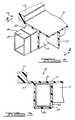
- a pickup box 10 for a pickup truck which pickup box comprises a reinforced moulded structure comprising an essentially one-piece unitary plastic body having a front wall 12, side walls 14, 15 and a generally planar platform portion 16 providing a horizontal surface area.
- the generally planar platform 16 is seen to comprise upstanding ribs 17.
- front wall 12 is seen to comprise ribs 18.
- Additional strengthening features include underside ribs 19, upper edge flanges 20, various areas of increased thickness and other features recognisable to the skilled of the art.
- a hollow beam section in a moulded plastic body can add strength to the plastic body with excellent incremental strength-to-weight ratio.
- a hollow beam section 25 is formed in the plastic body. This portion of the plastic body is unitary with the platform portion 16 and can be seen to be substantially coplanar with platform portion 16. Hollow beam section 25 extends along and downwardly from lower surface 27 of the platform portion to strengthen the platform portion.
- Hollow beam section 25 of plastic body 10 can be seen to have been moulded around forming mandrel 30.
- the platform portion 16 of pickup box 10 in Figs. 1-3 further comprises additional elongate members 30 (not shown) running longitudinally within hollow beam sections under generally planar surface 16, extending downwardly from lower surface 27 and generally parallel to elongate member 30 seen in Figs. 2 and 3.
- the elongate member 30 is proximate the exterior surface area of the platform portion of the plastic body, that is, it is proximate surface 16 of the pickup box.
- the rectilinear metal tube which forms the elongate member 30 has a substantially planar wall portion 31 which is proximate and substantially coplanar with exterior surface area 16.
- forming mandrel 30 preferably is a hollow, rectilinear aluminium alloy tube in view of the great strength to weight ratio and formability thereof.
- the forming mandrel is sufficiently strong to act, itself, as a reinforcing member within the plastic body.
- Additional suitable materials for elongate members which are to act as a forming mandrel for hollow beam sections of the plastic body are commercially available and will be readily apparent to the skilled of the art in view of the present disclosure.
- Elongate members to act as reinforcing members, but not necessarily as forming mandrels for a hollow box section in the plastic body include for example, metal wire and rods. Numerous alternative materials for elongate members which are to act as a reinforcing member in the plastic body will be apparent to those skilled in the art in view of the present disclosure.
- the surface to surface contact of the metal tube 30 with the plastic of a structure body could cause unacceptable distortions, squeaks and like noises during use of the pickup box (or other embodiment of the invention).
- This is particularly the case, for reasons discussed above, where the elongate member has a large surface interface with the plastic body, such as when the forming mandrel is formed as a hollow tube and has a thermal expansion coefficient significantly different from that of the plastic.
- a thin layer 35 of resilient material is provided mediate the plastic body and the exterior surface of the metal tube.
- the resilient layer should be sufficiently thick and sufficiently resilient to accommodate, without permanent dislocation or rupture, the relative movement of the elongate member within the plastic body under the conditions encountered in the use environment of the reinforced structure. In the case of a pickup box bed, for example, this typically would include a temperature range of approximately -20/F to +110/F and variable and shifting loads carried on the bed.
- resilient is meant that the layer has sufficient elastic deformability to accommodate the relative movement of the elongate member within the plastic body without significant adverse dislocation or rupture of the layer.
- significant adverse rupture or dislocation means that which would prevent the resilient layer from performing its function, e.g., reducing squeaks and like noises, preventing surface to surface contact between the plastic and the elongate member, etc.
- the resilient layer 35 forms an interfacial adhesive bond with the adjacent surfaces of the plastic body and the elongate member 30. With or without such adhesive interfacial bond, however, the resilient layer will be sandwiched between the plastic body and the elongate member such that the resilient layer fills the gap between the elongate member and the plastic body.
- Numerous materials suitable for the resilient layer are commercially available and will be apparent to the skilled of the art in view of the present disclosure. Exemplary of such materials are natural and synthetic rubbers.
- Preferred materials include ethylene/propylene rubbers such as EPDM, polybutadiene rubbers, nitrile rubbers and silicone rubbers such as the injection mouldable liquid silicone rubbers, e.g., those available from Mobay Corporation, Pittsburgh, PA under the trade name Baysilone LSR.
- the plastic body can be either filament reinforced plastic composite (FRP composite) or unreinforced plastic.
- FRP composite filament reinforced plastic composite
- Suitable materials include unfilled plastics and FRP composites mentioned above, such as SMC, BMC and HMC.
- the filamentary reinforcement material can be any of those well known to the skilled of the art, such as fibreglass, aramid fibres, carbon fibres and any combination thereof.
- Suitable plastics also include, for example, epoxy, polyester and vinyl ester resins which can be used in compression or resin transfer moulding methods well known to the skilled of the art for producing reinforced structures.
- the pickup box of Figs. 1-3 and like reinforced structures of the invention can be mass produced using commercially available methods, such as compression moulding of HMC which is preferred, to achieve high quality products.
- An elongate member comprising a metal tube such as steel or preferably aluminium is light yet sufficiently strong to act as a forming mandrel for the formation of a hollow beam section during the compression moulding of vinyl ester based HMC and the like.
- the elongate member itself contributes to the strength of the reinforced structure.
- the critical resilient layer mediate the elongate member and the plastic body avoids or minimises distortions, squeaks and like noises which would prevent the reinforced structure from meeting the high quality standards of motor vehicle and like applications and provides other structural advantages which will be apparent to the skilled of the art in view of this disclosure.
- the resilient material can be put onto the elongate exterior surface of the elongate member by any of various methods and techniques.
- Known methods include, for example, painting and injection moulding the resilient material onto the elongate member.
- the elongate member can be positioned within the cavity of an injection moulding tool and the resilient material, for example, injection mouldable liquid silicone rubber, thereafter injected into the moulding tool cavity.
- the resilient material for example, injection mouldable liquid silicone rubber
- the elongate member with the layer of resilient material thereon can be introduced into the cavity of a moulding tool. That is, the elongate member with the layer of resilient material can be manually or automatically placed into appropriate position within the moulding tool cavity. Plastic in a mouldable condition is then introduced into the moulding tool cavity.
- the moulding tool cavity can be fashioned to accommodate the desired number.
- one or more elongate members with layers of resilient material thereon can be placed into the cavity of an injection moulding tool and unreinforced plastic thereafter injected into the cavity. After the plastic is introduced into the cavity, it is moulded by the moulding tool to at least partially envelop the elongate member.
- the layer of resilient material on the elongate member is thereby sandwiched between the plastic and the exterior surface of the elongate member.
- the reinforced structure can be removed from the moulding tool cavity.
- the plastic body be an FRP composite, particularly in the case of load bearing structures within the scope of the invention.
- load bearing means that the reinforced structure is to be used in an environment in which it bears or carries a load either full time or is adapted to carry a load such as in the case of the pickup box of a pickup truck.
- the manner in which it is introduced into the cavity of the moulding tool along with the elongate member and the plastic will depend, in part, on the moulding methods being used.
- such material comprises both the plastic and the filament reinforcement material which, therefore, are introduced together into the moulding tool cavity.
- the reinforcement material typically will be introduced into the moulding tool cavity carried on the elongate member exterior of the resilient material. The moulding tool then is closed and the plastic, typically low viscosity thermoset plastic, is injected into the cavity.
Landscapes
- Engineering & Computer Science (AREA)
- Chemical & Material Sciences (AREA)
- Mechanical Engineering (AREA)
- Composite Materials (AREA)
- Architecture (AREA)
- Structural Engineering (AREA)
- Combustion & Propulsion (AREA)
- Transportation (AREA)
- Manufacturing & Machinery (AREA)
- Materials Engineering (AREA)
- Health & Medical Sciences (AREA)
- Chemical Kinetics & Catalysis (AREA)
- Medicinal Chemistry (AREA)
- Polymers & Plastics (AREA)
- Organic Chemistry (AREA)
- Body Structure For Vehicles (AREA)
- Laminated Bodies (AREA)
- Moulding By Coating Moulds (AREA)
Applications Claiming Priority (2)
| Application Number | Priority Date | Filing Date | Title |
|---|---|---|---|
| US07/253,654 US4976490A (en) | 1988-10-05 | 1988-10-05 | Reinforced composite structure |
| US253654 | 1988-10-05 |
Publications (2)
| Publication Number | Publication Date |
|---|---|
| EP0363042A1 true EP0363042A1 (fr) | 1990-04-11 |
| EP0363042B1 EP0363042B1 (fr) | 1993-05-05 |
Family
ID=22961158
Family Applications (1)
| Application Number | Title | Priority Date | Filing Date |
|---|---|---|---|
| EP89309555A Expired - Lifetime EP0363042B1 (fr) | 1988-10-05 | 1989-09-20 | Structure composite renforcée |
Country Status (4)
| Country | Link |
|---|---|
| US (1) | US4976490A (fr) |
| EP (1) | EP0363042B1 (fr) |
| CA (1) | CA1329818C (fr) |
| DE (1) | DE68906346D1 (fr) |
Cited By (1)
| Publication number | Priority date | Publication date | Assignee | Title |
|---|---|---|---|---|
| DE102012006528A1 (de) * | 2012-03-29 | 2013-10-02 | GM Global Technology Operations LLC (n.d. Ges. d. Staates Delaware) | Bodenstruktur einer Kraftfahrzeugkarosserie |
Families Citing this family (59)
| Publication number | Priority date | Publication date | Assignee | Title |
|---|---|---|---|---|
| US6478356B1 (en) * | 2000-01-05 | 2002-11-12 | Mark Wayne | Cargo area structure |
| US5271687A (en) * | 1992-04-03 | 1993-12-21 | Ford Motor Company | Space frame joint construction |
| US5209541A (en) * | 1992-04-13 | 1993-05-11 | Ford Motor Company | Space frame joint construction |
| US5228259A (en) * | 1992-04-29 | 1993-07-20 | Ford Motor Company | Space frame connector |
| US5320403A (en) * | 1992-04-29 | 1994-06-14 | Ford Motor Company | Space frame torque box |
| EP0568215A1 (fr) * | 1992-04-29 | 1993-11-03 | Ford Motor Company Limited | Structure porteuse pour véhicules |
| US5332281A (en) * | 1992-04-30 | 1994-07-26 | Ford Motor Company | Space frame construction |
| US5213386A (en) * | 1992-05-11 | 1993-05-25 | Ford Motor Company | Space frame construction |
| US5343666A (en) * | 1992-10-28 | 1994-09-06 | Ford Motor Company | Space frame joint construction |
| US5421634A (en) * | 1993-08-23 | 1995-06-06 | Hackett; Henry E. | Truck bed and truck liner |
| US5660427A (en) * | 1995-03-03 | 1997-08-26 | The Budd Company | Hybrid vehicle |
| US5730485A (en) * | 1995-06-07 | 1998-03-24 | Stoughton Composites, Inc. | Cargo transport vehicle floor assembly |
| US6023806A (en) * | 1996-09-30 | 2000-02-15 | Martin Marietta Materials, Inc. | Modular polymer matrix composite support structure and methods of constructing same |
| US6081955A (en) * | 1996-09-30 | 2000-07-04 | Martin Marietta Materials, Inc. | Modular polymer matrix composite support structure and methods of constructing same |
| US5794402A (en) * | 1996-09-30 | 1998-08-18 | Martin Marietta Materials, Inc. | Modular polymer matrix composite support structure and methods of constructing same |
| US6299246B1 (en) * | 1996-10-08 | 2001-10-09 | Rcc Regional Compact Car Ag | Plastic molded part and construction structure |
| US5992926A (en) * | 1997-07-30 | 1999-11-30 | Dana Corporation | Vehicular skid plate and cross member assembly |
| US6126228A (en) * | 1997-09-11 | 2000-10-03 | Lear Automotive Dearborn, Inc. | Wire harness foamed to trim panel |
| US6604778B2 (en) * | 1998-07-31 | 2003-08-12 | Durakon Industries, Inc. | Charge dissipating fiber reinforced plastic truck bed and liner |
| FR2783794B1 (fr) * | 1998-09-30 | 2001-01-26 | Valeo Thermique Moteur Sa | Facade avant composite metal/plastique surmoulee pour vehicule automobile |
| US6206458B1 (en) * | 1999-09-13 | 2001-03-27 | Daimlerchrysler Corporation | Vehicle body structure |
| US6457768B1 (en) * | 2000-05-18 | 2002-10-01 | Daimlerchrysler Corporation | Two-piece vehicle hardtop having an integral structural headliner |
| US20060237242A1 (en) * | 2000-09-25 | 2006-10-26 | Burke Robert J | Lightweight surface vehicle |
| US6523484B2 (en) * | 2000-12-20 | 2003-02-25 | Gunderson, Inc. | Center beam car with depressed cargo-carrying area |
| AU2002325029A1 (en) * | 2001-09-17 | 2003-04-01 | Collins And Aikman Automotive Company Inc. | Vehicle side storage box |
| US20040000746A1 (en) * | 2002-06-28 | 2004-01-01 | Montagna John C. | Method of manufacturing laminated bed and bed liner |
| US6945591B2 (en) * | 2002-06-28 | 2005-09-20 | Dana Corporation | Storage box for a pickup truck formed from metallic and composite materials |
| US6905137B2 (en) | 2002-11-21 | 2005-06-14 | Volvo Trucks North America, Inc. | Composite cross member system |
| US20050097853A1 (en) * | 2003-08-06 | 2005-05-12 | Copperweld Canada Inc. | Laminated structural members for vehicles |
| US7251915B2 (en) * | 2004-09-10 | 2007-08-07 | Pullman Industries, Inc. | Frame system for motor vehicle |
| US7578534B2 (en) * | 2005-11-03 | 2009-08-25 | Martin Marietta Materials, Inc. | Structural panel for a refrigerated trailer comprising an integrated bulkhead structure for promoting air flow |
| US7575264B1 (en) | 2006-03-14 | 2009-08-18 | Martin Marietta Materials, Inc. | Cargo bed structure comprising fiber reinforced polymer components |
| US20070216197A1 (en) * | 2006-03-14 | 2007-09-20 | Martin Marietta Materials, Inc. | Composite cargo floor structure having a reduced weight |
| US8534339B2 (en) * | 2011-10-12 | 2013-09-17 | The Boeing Company | Lightweight flexible mandrel and method for making the same |
| DE102012006527A1 (de) | 2012-03-29 | 2013-10-02 | GM Global Technology Operations LLC (n.d. Ges. d. Staates Delaware) | Bodenstruktur einer Kraftfahrzeugkarosserie |
| KR101500353B1 (ko) * | 2012-12-11 | 2015-03-09 | 현대자동차 주식회사 | 복합 차체 패널과 그 제조방법 및 이를 이용한 차체 구조 |
| US9604677B2 (en) * | 2014-06-13 | 2017-03-28 | Altec Industries, Inc. | Truck body assembly and methods of making and using same |
| US11305823B2 (en) | 2014-06-13 | 2022-04-19 | Altec Industries, Inc. | Sidepack storage compartment and methods of making and using same |
| US10940899B2 (en) | 2014-06-13 | 2021-03-09 | Altec Industries, Inc. | Truck body assembly and methods of making and using same |
| US11208156B2 (en) | 2014-06-13 | 2021-12-28 | Altec Industries, Inc. | Sidepack floor and methods of making and using same |
| US9090293B1 (en) * | 2014-06-26 | 2015-07-28 | Ford Global Technologies, Llc | Cargo bed support assembly for a truck |
| US10596950B2 (en) | 2015-02-23 | 2020-03-24 | Wabash National, L.P. | Composite refrigerated truck body and method of making the same |
| US10549789B2 (en) | 2015-09-08 | 2020-02-04 | Wabash National, L.P. | Joining a rail member to a composite trailer structure |
| MX2018002939A (es) | 2015-09-08 | 2018-06-18 | Wabash National Lp | Union de ensamble de suspension a una estructura de remolque compuesta. |
| MX2016013715A (es) | 2015-10-23 | 2017-12-20 | Wabash National Lp | Moldes extruidos y metodos para fabricar paneles de camion compuestos. |
| US10329763B2 (en) | 2016-02-24 | 2019-06-25 | Wabash National, L.P. | Composite floor structure and method of making the same |
| US10479419B2 (en) | 2016-02-24 | 2019-11-19 | Wabash National, L.P. | Composite refrigerated semi-trailer and method of making the same |
| US10239566B2 (en) | 2016-02-24 | 2019-03-26 | Wabash National, L.P. | Composite floor for a dry truck body |
| US10479405B2 (en) | 2016-08-31 | 2019-11-19 | Wabash National, L.P. | Mounting bracket for a composite truck body floor |
| US10407103B2 (en) | 2017-01-11 | 2019-09-10 | Wabash National, L.P. | Mounting bracket for a truck body and method for mounting a composite truck body to a chassis |
| US10461383B2 (en) | 2017-08-07 | 2019-10-29 | Ford Global Technologies, Llc | Battery enclosure having a composite structure with a coolant channel |
| CA3206527A1 (fr) | 2017-08-10 | 2019-02-10 | Wabash National, L.P. | Poutre transversale de plancher en composite et methode de fabrication associee |
| AU2018220122B2 (en) | 2017-08-25 | 2022-12-01 | Wabash National, L.P. | Composite floor structure with embedded hardpoint connector and method of making the same |
| DE202018103848U1 (de) * | 2018-07-05 | 2018-07-19 | Hbpo Gmbh | Strukturbauteil |
| US10906594B2 (en) * | 2019-05-30 | 2021-02-02 | Toyota Motor Engineering & Manufacturing North America, Inc. | Vehicular body structure |
| US11155300B1 (en) * | 2020-04-20 | 2021-10-26 | Toyota Motor Engineering & Manufacturing North America, Inc. | Vehicular body structural arrangement |
| US12337903B2 (en) | 2021-03-12 | 2025-06-24 | Wabash National, L.P. | Reinforced preforms for optimized composite structures |
| US12539802B2 (en) | 2021-12-07 | 2026-02-03 | Wabash National, L.P. | Embedded mounting inserts |
| US20240051613A1 (en) * | 2022-08-15 | 2024-02-15 | Toyota Motor Engineering & Manufacturing North America, Inc. | Truck bed deck floors with reinforcing rib patterns and trucks including deck floors with reinforcing rib patterns |
Citations (8)
| Publication number | Priority date | Publication date | Assignee | Title |
|---|---|---|---|---|
| DE1238349B (de) * | 1962-06-28 | 1967-04-06 | Maschf Augsburg Nuernberg Ag | Einrichtung zum Verbinden eines Kasten- oder Profiltraegers mit der plattenfoermigenAussenwand eines Fahrzeuges |
| DE1704450A1 (de) * | 1967-03-01 | 1971-05-19 | Paul Algrain | Verfahren zur Herstellung eines Grundgestells oder Rahmens aus waermhaertbarem Kunststoff mit darin fest eingebettetem Anbauteil |
| DE2030550A1 (en) * | 1970-06-20 | 1971-12-30 | Berne & Giller Gmbh | Thermoplastic bonding strip - fastening a flexible cover onto an unfinished body |
| DE2517604A1 (de) * | 1974-04-25 | 1975-11-20 | Worldwide Plastics Dev | Verfahren und vorrichtung zum herstellen von formstuecken |
| DE2908346A1 (de) * | 1979-03-03 | 1980-09-11 | Wilfried Ing Grad Droege | Rahmen- und/oder strukturbauelement |
| DE3408994C1 (de) * | 1984-03-12 | 1985-10-17 | Standard Bauchemie Profilsysteme GmbH, 1000 Berlin | Aus Polyurethan-Schaumstoff bestehendes Profilteil |
| US4682809A (en) * | 1984-12-05 | 1987-07-28 | Heinrich Huss | Car body |
| DE3608223A1 (de) * | 1986-03-12 | 1987-10-15 | Huehoco Bandeisen Und Metallwa | Traegerband aus metall fuer profilleisten mit mantel und zier- oder funktionsstreifen |
Family Cites Families (18)
| Publication number | Priority date | Publication date | Assignee | Title |
|---|---|---|---|---|
| GB526159A (en) * | 1938-03-09 | 1940-09-11 | Audi Ag | Improvements in or relating to vehicle bodies |
| US2404904A (en) * | 1940-11-06 | 1946-07-30 | Owens Corning Fiberglass Corp | Bonding glass fabrics to inorganic solids |
| US3058165A (en) * | 1953-11-12 | 1962-10-16 | Purvis Matthew Kenneth | Method of manufacturing articles from reinforced synthetic resin |
| US3082485A (en) * | 1958-04-07 | 1963-03-26 | American Metal Prod | Elements having low friction material compacted on teh face thereof |
| NL122900C (fr) * | 1960-11-25 | |||
| US3481643A (en) * | 1967-08-23 | 1969-12-02 | Elkhart Bridge & Iron Co Inc | Vehicle chassis construction |
| DE1655650A1 (de) * | 1967-12-07 | 1971-08-12 | Volkswagenwerk Ag | Selbsttragende Kunststoff-Kraftfahrzeugkarosserie |
| US3637252A (en) * | 1970-03-27 | 1972-01-25 | Avco Corp | Vehicle body construction |
| US3999930A (en) * | 1973-03-02 | 1976-12-28 | Telbizoff Louis E | Mold assembly for forming and curing flexible seals |
| US3962394A (en) * | 1975-06-02 | 1976-06-08 | Trw Inc. | Method for molding fiber reinforced composite tube |
| FR2454399A2 (fr) * | 1978-09-14 | 1980-11-14 | Sovam | Carrosserie pour vehicule, ainsi que les vehicules pourvus de cette carrosserie |
| GB2067455A (en) * | 1979-02-20 | 1981-07-30 | Rolls Royce | Composite structure |
| DE3016295A1 (de) * | 1980-04-28 | 1981-11-05 | Aktiengesellschaft Adolph Saurer, 9320 Arbon | Wagenkasten, insbesondere fuer kraftfahrzeuge |
| FR2504236A1 (fr) * | 1981-04-16 | 1982-10-22 | Galli Franck | Paroi composite isolante a parements exterieurs en pvc |
| US4440434A (en) * | 1981-12-24 | 1984-04-03 | Aldo Celli | Vehicle body construction |
| DE3412359A1 (de) * | 1984-04-03 | 1985-10-10 | Gebr. Happich Gmbh, 5600 Wuppertal | Polsterkoerper, insbesondere fuer fahrzeuge |
| GB2166065A (en) * | 1984-10-27 | 1986-04-30 | Webco Ltd | Insulated pipeline |
| GB8620412D0 (en) * | 1986-08-21 | 1986-10-01 | Wardill G A | Load bearing structures |
-
1988
- 1988-10-05 US US07/253,654 patent/US4976490A/en not_active Expired - Fee Related
-
1989
- 1989-08-24 CA CA000609270A patent/CA1329818C/fr not_active Expired - Fee Related
- 1989-09-20 DE DE8989309555T patent/DE68906346D1/de not_active Expired - Lifetime
- 1989-09-20 EP EP89309555A patent/EP0363042B1/fr not_active Expired - Lifetime
Patent Citations (8)
| Publication number | Priority date | Publication date | Assignee | Title |
|---|---|---|---|---|
| DE1238349B (de) * | 1962-06-28 | 1967-04-06 | Maschf Augsburg Nuernberg Ag | Einrichtung zum Verbinden eines Kasten- oder Profiltraegers mit der plattenfoermigenAussenwand eines Fahrzeuges |
| DE1704450A1 (de) * | 1967-03-01 | 1971-05-19 | Paul Algrain | Verfahren zur Herstellung eines Grundgestells oder Rahmens aus waermhaertbarem Kunststoff mit darin fest eingebettetem Anbauteil |
| DE2030550A1 (en) * | 1970-06-20 | 1971-12-30 | Berne & Giller Gmbh | Thermoplastic bonding strip - fastening a flexible cover onto an unfinished body |
| DE2517604A1 (de) * | 1974-04-25 | 1975-11-20 | Worldwide Plastics Dev | Verfahren und vorrichtung zum herstellen von formstuecken |
| DE2908346A1 (de) * | 1979-03-03 | 1980-09-11 | Wilfried Ing Grad Droege | Rahmen- und/oder strukturbauelement |
| DE3408994C1 (de) * | 1984-03-12 | 1985-10-17 | Standard Bauchemie Profilsysteme GmbH, 1000 Berlin | Aus Polyurethan-Schaumstoff bestehendes Profilteil |
| US4682809A (en) * | 1984-12-05 | 1987-07-28 | Heinrich Huss | Car body |
| DE3608223A1 (de) * | 1986-03-12 | 1987-10-15 | Huehoco Bandeisen Und Metallwa | Traegerband aus metall fuer profilleisten mit mantel und zier- oder funktionsstreifen |
Cited By (1)
| Publication number | Priority date | Publication date | Assignee | Title |
|---|---|---|---|---|
| DE102012006528A1 (de) * | 2012-03-29 | 2013-10-02 | GM Global Technology Operations LLC (n.d. Ges. d. Staates Delaware) | Bodenstruktur einer Kraftfahrzeugkarosserie |
Also Published As
| Publication number | Publication date |
|---|---|
| DE68906346D1 (de) | 1993-06-09 |
| CA1329818C (fr) | 1994-05-24 |
| US4976490A (en) | 1990-12-11 |
| EP0363042B1 (fr) | 1993-05-05 |
Similar Documents
| Publication | Publication Date | Title |
|---|---|---|
| EP0363042B1 (fr) | Structure composite renforcée | |
| US11820088B2 (en) | Structural reinforcements | |
| US6458309B1 (en) | Method for fabricating an advanced composite aerostructure article having an integral co-cured fly away hollow mandrel | |
| US6439649B1 (en) | Pickup truck box | |
| US8530015B2 (en) | Reinforcement of hollow profiles | |
| US6003274A (en) | Lightweight laminate reinforcing web | |
| US6905745B2 (en) | Structural foam | |
| US20080156425A1 (en) | Method of making a body part or chassis part of a motor vehicle | |
| KR101597852B1 (ko) | 강화 조립체 | |
| JPH11129931A (ja) | 車両スキッド・プレート及びクロス・メンバ・アセンブリ | |
| US10919579B2 (en) | Composite floor structure with embedded hardpoint connector and method of making the same | |
| EP1134069A1 (fr) | Structure creuse en resine renforcee par des fibres et son procede de fabrication | |
| US9914490B2 (en) | Frame structure with at least one console for connecting further components, method for producing and motor vehicle body | |
| US20030006576A1 (en) | Molded running board | |
| EP3677397B1 (fr) | Pièce composite | |
| GB2375328A (en) | Reinforcing element for hollow structural member | |
| EP3595918A1 (fr) | Composant de châssis pour un véhicule automobile et procédé de fabrication d'un composant de châssis | |
| US5501825A (en) | Process for the manufacture of a shaped ski | |
| JPH01272426A (ja) | 自動車の車体部材、特に後方補助翼又はベケの製造方法及び該方法によって製造した車体部材 | |
| JP3500357B2 (ja) | シーリングプロファイルと接着ストリップとを備えたシーリング部材 | |
| JP4425647B2 (ja) | 接合端を有するfrp成形物、その製造方法及び金属構造物を接合したfrp成形物 | |
| EP0702619A1 (fr) | Berceau de batterie en matiere thermoplastique renforcee par des fibres, et son procede de fabrication | |
| LU506056B1 (en) | Reinforced panel and reinforced apparatus | |
| JP7709019B2 (ja) | 自動車用ルーフパネル構造 | |
| US11827277B2 (en) | Reinforcement with integrated stop device |
Legal Events
| Date | Code | Title | Description |
|---|---|---|---|
| PUAI | Public reference made under article 153(3) epc to a published international application that has entered the european phase |
Free format text: ORIGINAL CODE: 0009012 |
|
| AK | Designated contracting states |
Kind code of ref document: A1 Designated state(s): DE FR GB |
|
| 17P | Request for examination filed |
Effective date: 19900921 |
|
| 17Q | First examination report despatched |
Effective date: 19911007 |
|
| GRAA | (expected) grant |
Free format text: ORIGINAL CODE: 0009210 |
|
| AK | Designated contracting states |
Kind code of ref document: B1 Designated state(s): DE FR GB |
|
| PG25 | Lapsed in a contracting state [announced via postgrant information from national office to epo] |
Ref country code: FR Effective date: 19930505 Ref country code: DE Effective date: 19930505 |
|
| REF | Corresponds to: |
Ref document number: 68906346 Country of ref document: DE Date of ref document: 19930609 |
|
| REG | Reference to a national code |
Ref country code: GB Ref legal event code: 746 |
|
| EN | Fr: translation not filed | ||
| PLBE | No opposition filed within time limit |
Free format text: ORIGINAL CODE: 0009261 |
|
| STAA | Information on the status of an ep patent application or granted ep patent |
Free format text: STATUS: NO OPPOSITION FILED WITHIN TIME LIMIT |
|
| 26N | No opposition filed | ||
| PGFP | Annual fee paid to national office [announced via postgrant information from national office to epo] |
Ref country code: GB Payment date: 19950830 Year of fee payment: 7 |
|
| PG25 | Lapsed in a contracting state [announced via postgrant information from national office to epo] |
Ref country code: GB Effective date: 19960920 |
|
| GBPC | Gb: european patent ceased through non-payment of renewal fee |
Effective date: 19960920 |