EP0363153A2 - Blattkantendetektor - Google Patents
Blattkantendetektor Download PDFInfo
- Publication number
- EP0363153A2 EP0363153A2 EP89310109A EP89310109A EP0363153A2 EP 0363153 A2 EP0363153 A2 EP 0363153A2 EP 89310109 A EP89310109 A EP 89310109A EP 89310109 A EP89310109 A EP 89310109A EP 0363153 A2 EP0363153 A2 EP 0363153A2
- Authority
- EP
- European Patent Office
- Prior art keywords
- sheet
- edge
- predetermined distance
- control logic
- absence
- Prior art date
- Legal status (The legal status is an assumption and is not a legal conclusion. Google has not performed a legal analysis and makes no representation as to the accuracy of the status listed.)
- Granted
Links
Images


Classifications
-
- G—PHYSICS
- G03—PHOTOGRAPHY; CINEMATOGRAPHY; ANALOGOUS TECHNIQUES USING WAVES OTHER THAN OPTICAL WAVES; ELECTROGRAPHY; HOLOGRAPHY
- G03G—ELECTROGRAPHY; ELECTROPHOTOGRAPHY; MAGNETOGRAPHY
- G03G15/00—Apparatus for electrographic processes using a charge pattern
- G03G15/65—Apparatus which relate to the handling of copy material
- G03G15/6588—Apparatus which relate to the handling of copy material characterised by the copy material, e.g. postcards, large copies, multi-layered materials, coloured sheet material
-
- B—PERFORMING OPERATIONS; TRANSPORTING
- B65—CONVEYING; PACKING; STORING; HANDLING THIN OR FILAMENTARY MATERIAL
- B65H—HANDLING THIN OR FILAMENTARY MATERIAL, e.g. SHEETS, WEBS, CABLES
- B65H7/00—Controlling article feeding, separating, pile-advancing, or associated apparatus, to take account of incorrect feeding, absence of articles, or presence of faulty articles
- B65H7/02—Controlling article feeding, separating, pile-advancing, or associated apparatus, to take account of incorrect feeding, absence of articles, or presence of faulty articles by feelers or detectors
- B65H7/06—Controlling article feeding, separating, pile-advancing, or associated apparatus, to take account of incorrect feeding, absence of articles, or presence of faulty articles by feelers or detectors responsive to presence of faulty articles or incorrect separation or feed
-
- B—PERFORMING OPERATIONS; TRANSPORTING
- B65—CONVEYING; PACKING; STORING; HANDLING THIN OR FILAMENTARY MATERIAL
- B65H—HANDLING THIN OR FILAMENTARY MATERIAL, e.g. SHEETS, WEBS, CABLES
- B65H7/00—Controlling article feeding, separating, pile-advancing, or associated apparatus, to take account of incorrect feeding, absence of articles, or presence of faulty articles
- B65H7/02—Controlling article feeding, separating, pile-advancing, or associated apparatus, to take account of incorrect feeding, absence of articles, or presence of faulty articles by feelers or detectors
- B65H7/14—Controlling article feeding, separating, pile-advancing, or associated apparatus, to take account of incorrect feeding, absence of articles, or presence of faulty articles by feelers or detectors by photoelectric feelers or detectors
-
- B—PERFORMING OPERATIONS; TRANSPORTING
- B65—CONVEYING; PACKING; STORING; HANDLING THIN OR FILAMENTARY MATERIAL
- B65H—HANDLING THIN OR FILAMENTARY MATERIAL, e.g. SHEETS, WEBS, CABLES
- B65H2301/00—Handling processes for sheets or webs
- B65H2301/30—Orientation, displacement, position of the handled material
- B65H2301/33—Modifying, selecting, changing orientation
- B65H2301/333—Inverting
- B65H2301/3331—Involving forward reverse transporting means
- B65H2301/33312—Involving forward reverse transporting means forward reverse rollers pairs
-
- B—PERFORMING OPERATIONS; TRANSPORTING
- B65—CONVEYING; PACKING; STORING; HANDLING THIN OR FILAMENTARY MATERIAL
- B65H—HANDLING THIN OR FILAMENTARY MATERIAL, e.g. SHEETS, WEBS, CABLES
- B65H2511/00—Dimensions; Position; Numbers; Identification; Occurrences
- B65H2511/10—Size; Dimensions
- B65H2511/16—Irregularities, e.g. protuberances
-
- B—PERFORMING OPERATIONS; TRANSPORTING
- B65—CONVEYING; PACKING; STORING; HANDLING THIN OR FILAMENTARY MATERIAL
- B65H—HANDLING THIN OR FILAMENTARY MATERIAL, e.g. SHEETS, WEBS, CABLES
- B65H2511/00—Dimensions; Position; Numbers; Identification; Occurrences
- B65H2511/20—Location in space
-
- B—PERFORMING OPERATIONS; TRANSPORTING
- B65—CONVEYING; PACKING; STORING; HANDLING THIN OR FILAMENTARY MATERIAL
- B65H—HANDLING THIN OR FILAMENTARY MATERIAL, e.g. SHEETS, WEBS, CABLES
- B65H2511/00—Dimensions; Position; Numbers; Identification; Occurrences
- B65H2511/50—Occurence
- B65H2511/51—Presence
-
- B—PERFORMING OPERATIONS; TRANSPORTING
- B65—CONVEYING; PACKING; STORING; HANDLING THIN OR FILAMENTARY MATERIAL
- B65H—HANDLING THIN OR FILAMENTARY MATERIAL, e.g. SHEETS, WEBS, CABLES
- B65H2511/00—Dimensions; Position; Numbers; Identification; Occurrences
- B65H2511/50—Occurence
- B65H2511/51—Presence
- B65H2511/514—Particular portion of element
-
- B—PERFORMING OPERATIONS; TRANSPORTING
- B65—CONVEYING; PACKING; STORING; HANDLING THIN OR FILAMENTARY MATERIAL
- B65H—HANDLING THIN OR FILAMENTARY MATERIAL, e.g. SHEETS, WEBS, CABLES
- B65H2511/00—Dimensions; Position; Numbers; Identification; Occurrences
- B65H2511/50—Occurence
- B65H2511/515—Absence
-
- B—PERFORMING OPERATIONS; TRANSPORTING
- B65—CONVEYING; PACKING; STORING; HANDLING THIN OR FILAMENTARY MATERIAL
- B65H—HANDLING THIN OR FILAMENTARY MATERIAL, e.g. SHEETS, WEBS, CABLES
- B65H2515/00—Physical entities not provided for in groups B65H2511/00 or B65H2513/00
- B65H2515/60—Optical characteristics, e.g. colour, light
-
- B—PERFORMING OPERATIONS; TRANSPORTING
- B65—CONVEYING; PACKING; STORING; HANDLING THIN OR FILAMENTARY MATERIAL
- B65H—HANDLING THIN OR FILAMENTARY MATERIAL, e.g. SHEETS, WEBS, CABLES
- B65H2553/00—Sensing or detecting means
- B65H2553/40—Sensing or detecting means using optical, e.g. photographic, elements
- B65H2553/41—Photoelectric detectors
- B65H2553/412—Photoelectric detectors in barrier arrangements, i.e. emitter facing a receptor element
-
- B—PERFORMING OPERATIONS; TRANSPORTING
- B65—CONVEYING; PACKING; STORING; HANDLING THIN OR FILAMENTARY MATERIAL
- B65H—HANDLING THIN OR FILAMENTARY MATERIAL, e.g. SHEETS, WEBS, CABLES
- B65H2701/00—Handled material; Storage means
- B65H2701/10—Handled articles or webs
- B65H2701/13—Parts concerned of the handled material
- B65H2701/131—Edges
- B65H2701/1311—Edges leading edge
-
- B—PERFORMING OPERATIONS; TRANSPORTING
- B65—CONVEYING; PACKING; STORING; HANDLING THIN OR FILAMENTARY MATERIAL
- B65H—HANDLING THIN OR FILAMENTARY MATERIAL, e.g. SHEETS, WEBS, CABLES
- B65H2701/00—Handled material; Storage means
- B65H2701/10—Handled articles or webs
- B65H2701/13—Parts concerned of the handled material
- B65H2701/131—Edges
- B65H2701/1313—Edges trailing edge
-
- G—PHYSICS
- G03—PHOTOGRAPHY; CINEMATOGRAPHY; ANALOGOUS TECHNIQUES USING WAVES OTHER THAN OPTICAL WAVES; ELECTROGRAPHY; HOLOGRAPHY
- G03G—ELECTROGRAPHY; ELECTROPHOTOGRAPHY; MAGNETOGRAPHY
- G03G2215/00—Apparatus for electrophotographic processes
- G03G2215/00362—Apparatus for electrophotographic processes relating to the copy medium handling
- G03G2215/00367—The feeding path segment where particular handling of the copy medium occurs, segments being adjacent and non-overlapping. Each segment is identified by the most downstream point in the segment, so that for instance the segment labelled "Fixing device" is referring to the path between the "Transfer device" and the "Fixing device"
- G03G2215/00417—Post-fixing device
- G03G2215/00421—Discharging tray, e.g. devices stabilising the quality of the copy medium, postfixing-treatment, inverting, sorting
-
- G—PHYSICS
- G03—PHOTOGRAPHY; CINEMATOGRAPHY; ANALOGOUS TECHNIQUES USING WAVES OTHER THAN OPTICAL WAVES; ELECTROGRAPHY; HOLOGRAPHY
- G03G—ELECTROGRAPHY; ELECTROPHOTOGRAPHY; MAGNETOGRAPHY
- G03G2215/00—Apparatus for electrophotographic processes
- G03G2215/00362—Apparatus for electrophotographic processes relating to the copy medium handling
- G03G2215/00367—The feeding path segment where particular handling of the copy medium occurs, segments being adjacent and non-overlapping. Each segment is identified by the most downstream point in the segment, so that for instance the segment labelled "Fixing device" is referring to the path between the "Transfer device" and the "Fixing device"
- G03G2215/00417—Post-fixing device
- G03G2215/0043—Refeeding path
- G03G2215/00438—Inverter of refeeding path
-
- G—PHYSICS
- G03—PHOTOGRAPHY; CINEMATOGRAPHY; ANALOGOUS TECHNIQUES USING WAVES OTHER THAN OPTICAL WAVES; ELECTROGRAPHY; HOLOGRAPHY
- G03G—ELECTROGRAPHY; ELECTROPHOTOGRAPHY; MAGNETOGRAPHY
- G03G2215/00—Apparatus for electrophotographic processes
- G03G2215/00362—Apparatus for electrophotographic processes relating to the copy medium handling
- G03G2215/00443—Copy medium
- G03G2215/00523—Other special types, e.g. tabbed
-
- G—PHYSICS
- G03—PHOTOGRAPHY; CINEMATOGRAPHY; ANALOGOUS TECHNIQUES USING WAVES OTHER THAN OPTICAL WAVES; ELECTROGRAPHY; HOLOGRAPHY
- G03G—ELECTROGRAPHY; ELECTROPHOTOGRAPHY; MAGNETOGRAPHY
- G03G2215/00—Apparatus for electrophotographic processes
- G03G2215/00362—Apparatus for electrophotographic processes relating to the copy medium handling
- G03G2215/00535—Stable handling of copy medium
- G03G2215/00611—Detector details, e.g. optical detector
-
- G—PHYSICS
- G03—PHOTOGRAPHY; CINEMATOGRAPHY; ANALOGOUS TECHNIQUES USING WAVES OTHER THAN OPTICAL WAVES; ELECTROGRAPHY; HOLOGRAPHY
- G03G—ELECTROGRAPHY; ELECTROPHOTOGRAPHY; MAGNETOGRAPHY
- G03G2215/00—Apparatus for electrophotographic processes
- G03G2215/00362—Apparatus for electrophotographic processes relating to the copy medium handling
- G03G2215/00535—Stable handling of copy medium
- G03G2215/00611—Detector details, e.g. optical detector
- G03G2215/00616—Optical detector
-
- G—PHYSICS
- G03—PHOTOGRAPHY; CINEMATOGRAPHY; ANALOGOUS TECHNIQUES USING WAVES OTHER THAN OPTICAL WAVES; ELECTROGRAPHY; HOLOGRAPHY
- G03G—ELECTROGRAPHY; ELECTROPHOTOGRAPHY; MAGNETOGRAPHY
- G03G2215/00—Apparatus for electrophotographic processes
- G03G2215/00362—Apparatus for electrophotographic processes relating to the copy medium handling
- G03G2215/00535—Stable handling of copy medium
- G03G2215/00687—Handling details
- G03G2215/007—Inverter not for refeeding purposes
-
- G—PHYSICS
- G03—PHOTOGRAPHY; CINEMATOGRAPHY; ANALOGOUS TECHNIQUES USING WAVES OTHER THAN OPTICAL WAVES; ELECTROGRAPHY; HOLOGRAPHY
- G03G—ELECTROGRAPHY; ELECTROPHOTOGRAPHY; MAGNETOGRAPHY
- G03G2215/00—Apparatus for electrophotographic processes
- G03G2215/00362—Apparatus for electrophotographic processes relating to the copy medium handling
- G03G2215/00535—Stable handling of copy medium
- G03G2215/00717—Detection of physical properties
- G03G2215/00721—Detection of physical properties of sheet position
Definitions
- This invention relates generally to an electrophotographic printing machine, and more particularly concerns an apparatus for discriminating between an edge of a copy sheet and a hole therein.
- a photoconductive member is charged to a substantially uniform potential so as to sensitize the surface thereof.
- the charged portion of the photoconductive member is exposed to a light image of an original document being reproduced. Exposure of the charged photoconductive member selectively dissipates the charge thereon in the irradiated areas.
- the latent image is developed by bringing a developer material into contact therewith.
- the developer material comprises toner particles adhering triboelectrically to carrier granules.
- the toner particles are attracted from the carrier granules to the latent image forming a toner powder image on the photoconductive member.
- the toner powder image is then transferred from the photoconductive member to a copy sheet.
- the toner particles are heated to permanently affix the powder image to the copy sheet.
- each copy sheet has information reproduced on both sides of the sheet, i.e. it is a duplex sheet.
- a duplex copy sheet is advanced to the finishing station, it is inverted in order to place the sheets in the proper sequence and orientation for binding or stapling.
- An inverter receives the leading edge of the sheet. The inversion process is completed with the former trailing edge becoming the leading edge and the former leading edge becoming the trailing edge. In order to determine when to advance the sheet from the inverter, it is necessary to determine when the trailing edge of the sheet has entered the inverter.
- an edge sensor such as a photosensor detects both the leading and trailing edges and actuates the inverter to advance the sheet therefrom after the trailing edge has been sensed.
- the photosensor will erroneously indicate that the holes in the trailing marginal region of the sheet are the trailing edge of the sheet and the inverter will be actuated prematurely to eject the sheet therefrom. Accordingly, in order to prevent the premature ejection of the copy sheet from the inverter, it is necessary to distinguish between the trailing edge and holes therein.
- Various approaches have been devised for detecting holes in sheets.
- US-A-4,302,105 discloses a laser which directs a beam onto a row of stepped mirrors.
- a row of Fresnel lenses are located directly behind a web. The web is being monitored to determine if there are holes therein.
- the Fresnel lenses concentrate the light which is incident on them through the holes onto a photoelectric converter.
- the photoelectric converters are associated with a processing circuit to detect the light transmitted through any holes in the web.
- US-A-4,323,311 describes an apparatus for detecting holes in sheet material, such as tin plate.
- the apparatus uses a laser for generating a beam that is reflected from a multifaceted mirror drum onto a pair of mirrors and then onto the moving sheet.
- Light collectors focus the laser beam transmitted through the sheet onto a photomultiplier.
- the signal from the photomultiplier is passed to a signal processing apparatus.
- US-A-4,485,949 discloses an infrared light source which transmits dual parallel beams onto a web having sprocket holes therein. Dual photodetectors receive the beam transmitted through the sprocket holes. The photodetectors are connected to a common "OR" output which validates presence of a sprocket hole.
- US-A-4,609,815 describes a light emitting diode which generates light rays onto a colored sheet. If the light emitting from the light emitting diode contacts the sheet, a weak intensity light is reflected toward a phototransistor. If a hole in the sheet is opposite the light emitting diode, the light emitted from the light emitting diode is strongly reflected by a reflector so that a strongly reflected light is received by the phototransistor. In this way, it is possible to detect the hole in the sheet.
- an apparatus for determining the location of an edge of a sheet includes means for advancing the sheet, and is characterised by means for distinguishing between the edge of the sheet and a hole in the marginal region thereof.
- an electrophotographic printing machine of the type in which it is necessary to discriminate between an edge of the copy sheet and a hole therein.
- the improvement in the printing machine includes means for advancing the sheet. Means are provided for distinguishing between the edge of the sheet and a hole in the marginal region thereof.
- Still another aspect of the features of the present invention includes a method of determining the edge of a sheet.
- the method includes the steps of advancing the sheet, and distinguishing between the edge of the sheet and a hole in the marginal region thereof.
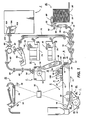
- FIG. 1 schematically depicts an electrophotographic printing machine incorporating the features of the present invention therein. It will become evident from the following discussion that the apparatus and method of the present invention may be employed in a wide variety of devices and is not specifically limited in its application to the particular embodiment or method of use described herein.
- the electrophotographic printing machine employs a photoconductive belt 10.
- the photoconductive belt 10 is made from a photoconductive material coated on a ground layer, which, in turn, is coated on a anti-curl backing layer.
- the photoconductive material is made from a transport layer coated on a generator layer.
- the transport layer transports positive charges from the generator layer.
- the interface layer is coated on the ground layer.
- the transport layer contains small molecules of di-m-tolydiphenylbiphenyldiamine dispersed in a polycarbonate.
- the generation layer is made from trigonal selenium.
- the grounding layer is made from a titanium coated Mylar. The ground layer is very thin and allows light to pass therethrough.
- Belt 10 moves in the direction of arrow 12 to advance successive portions of the photoconductive surface sequentially through the various processing stations disposed about the path of movement thereof.
- Belt 10 is entrained about stripping roller 14, tensioning roller 16, idler rollers 18, and drive roller 20.
- Stripping roller 14 and idler rollers 18 are mounted rotatably so as to rotate with belt 10.
- Tensioning roller 16 is resiliently urged against belt 10 to maintain belt 10 under the desired tension.
- Drive roller 20 is rotated by a motor coupled thereto by suitable means such as a belt drive. As roller 20 rotates, it advances belt 10 in the direction of arrow 12.
- corona generating devices 22 and 24 charge photoconductive belt 10 to a relatively high, substantially uniform potential.
- Corona generating device 22 places all of the required charge on photoconductive belt 10.
- Corona generating device 24 acts as a leveling device, and fills in any areas missed by corona generating device 22.
- a document handling unit indicated generally by the reference numeral 26, is positioned over platen 28 of the printing machine.
- Document handling unit 26 sequentially feeds documents from a stack of documents placed by the operator in the document stacking and holding tray.
- the original documents to be copied are loaded face up into the document tray on top of the document handling unit.
- a document feeder located below the tray forwards the bottom document in the stack to rollers. The rollers advance the document onto platen 28.
- a belt transport is lowered onto the platen with the original document being interposed between the platen and the belt transport.
- the original document is returned to the document tray from platen 28 by either of two paths.
- Imaging of a document is achieved by two Xenon flash lamps 30 mounted in the optics cavity which illuminate the document on platen 28. Light rays reflected from the document are transmitted through lens 32. Lens 32 focuses light images of the original document onto the charged portion of the photoconductive surface of belt 10 to selectively dissipate the charge thereon. This records an electrostatic latent image on photoconductive belt 10 which corresponds to the informational areas contained within the original document. Thereafter, photoconductive belt 10 advances the electrostatic latent image recorded thereon to development station C.
- a magnetic brush developer unit At development station C, a magnetic brush developer unit, indicated generally by the reference numeral 34, has three developer rolls, indicated generally by the reference numerals 36, 38 and 40.
- a paddle wheel 42 picks up developer material and delivers it to the developer rolls. When developer material reaches rolls 36 and 38, it is magnetically split between the rolls with half of the developer material being delivered to each roll.
- Photoconductive belt 10 is partially wrapped about rolls 36 and 38 to form extended development zones.
- Developer roll 40 is a cleanup roll.
- Magnetic roll 44 is a carrier granule removal device adapted to remove any carrier granules adhering to belt 10.
- rolls 36 and 38 advance developer material into contact with the electrostatic latent image. The latent image attracts toner particles from the carrier granules of the developer material to form a toner powder image on the photoconductive surface of belt 10.
- Belt 10 then advances the toner powder image to transfer station D.
- a copy sheet is moved into contact with the toner powder image.
- photoconductive belt 10 is exposed to a pre-transfer light from a lamp (not shown) to reduce the attraction between photoconductive belt 10 and the toner powder image.
- a corona generating device 46 charges the copy sheet to the proper magnitude and polarity so that the copy sheet is tacked to photoconductive belt 10 and the toner powder image attracted from the photoconductive belt to the copy sheet.
- corona generator 48 charges the copy sheet to the opposite polarity to detack the copy sheet from belt 10.
- Conveyor 50 advances the copy sheet to fusing station E.
- Fusing station E includes a fuser assembly, indicated generally by the reference numeral 52 which permanently affixes the transferred toner powder image to the copy sheet.
- fuser assembly 52 includes a heated fuser roller 54 and a pressure roller 56 with the powder image on the copy sheet contacting fuser roller 54.
- the pressure roller is cammed against the fuser roller to provide the necessary pressure to fix the toner powder image to the copy sheet.
- the fuser roll is internally heated by a quartz lamp.
- a release agent, stored in a reservoir, is pumped to a metering roll.
- a trim blade trims off the excess release agent. The release agent transfers to a donor roll and then to the fuser roll.
- Decurler 58 bends the copy sheet in one direction to put a known curl in the copy sheet and then bends it in the opposite direction to remove that curl.
- Duplex solenoid gate 64 guides the sheet to the finishing station F or to duplex tray 66.
- Rolls 102 advance the sheet between opposed parallel plates 104 and 106.
- a sensor, indicated generally by the reference numeral 108 determines the location of the leading and trailing edges of the sheet. Further details of the portion of the finishing station F having sensor 108 and the method of determining the location of the trailing edge of the sheet will be described hereinafter with reference to Figures 2 through 4, inclusive.
- duplex solenoid gate 64 diverts the sheet into duplex tray 66.
- the duplex tray 66 provides an intermediate or buffer storage for those sheets that have been printed on one side and on which an image will be subsequently printed on the second, opposed side thereof, i.e. the sheets being duplexed.
- the sheets are stacked in duplex tray 66 face down on top of one another in the order in which they are copied.
- the simplex sheets in tray 66 are fed, in seriatim, by bottom feeder 68 from tray 66 back to transfer station D via conveyor 70 and rollers 72 for transfer of the toner powder image to the opposed sides of the copy sheets.
- bottom feeder 68 the proper or clean side of the copy sheet is positioned in contact with belt 10 at transfer station D so that the toner powder image is transferred thereto.
- the duplex sheet is then fed through the same path as the simplex sheet to be advanced to finishing station F.
- Copy sheets are fed to transfer station D from the secondary tray 74.
- the secondary tray 74 includes an elevator driven by a bidirectional AC motor.
- the controller has the ability to cause the motor to drive the tray up or down.
- sheet feeder 76 is a friction retard feeder utilizing a feed belt and take-away rolls to advance successive copy sheets to transport 70 which advances the sheets to rolls 72 and then to transfer station D.
- Copy sheets may also be fed to transfer station D from the auxiliary tray 78.
- the auxiliary tray 78 includes an elevator driven by a bidirectional AC motor. Its controller has the ability to drive the tray up or down. When the tray is in the down position, stacks of copy sheets are loaded thereon or unloaded therefrom. In the up position, successive copy sheets may be fed therefrom by sheet feeder 80.
- Sheet feeder 80 is a friction retard feeder utilizing a feed belt and take-away rolls to advance successive copy sheets to transport 70 which advances the sheets to rolls 72 and then to transfer station D.
- Secondary tray 74 and auxiliary tray 78 are secondary sources of copy sheets.
- a high capacity feeder indicated generally by the reference numeral 82, is the primary source of copy sheets.
- High capacity feeder 82 includes a tray 84 supported on an elevator 86. The elevator is driven by a bidirectional motor to move the tray up or down. In the up position, the copy sheets are advanced from the tray to transfer station D.
- a vacuum feed belt 88 feeds successive uppermost sheets from the stack to a take away drive roll 90 and idler rolls 92. The drive roll and idler rolls guide the sheet onto transport 93. Transport 93 and idler roll 95 advance the sheet to rolls 72 which, in turn, move the sheet to transfer station station D.
- photoconductive belt 10 passes beneath corona generating device 94 which charges the residual toner particles to the proper polarity. Thereafter, a precharge erase lamp (not shown), located inside photoconductive belt 10, discharges the photoconductive belt in preparation for the next charging cycle. Residual particles are removed from the photoconductive surface at cleaning station G.
- Cleaning station G includes an electrically biased cleaner brush 96 and two detoning rolls 98 and 100, i.e. waste and reclaim de-toning rolls. The reclaim roll is electrically biased negatively relative to the cleaner roll so as to remove toner particles therefrom.
- the waste roll is electrically biased positively relative to the reclaim roll so as to remove paper debris and wrong sign toner particles.
- the toner particles on the reclaim roll are scraped off and deposited in a reclaim auger (not shown), where it is transported out of the the rear of cleaning station G.
- the various machine functions are regulated by a controller.
- the controller is preferably a programmable microprocessor which controls all of the machine functions hereinbefore described.
- the controller provides a comparison count of the copy sheets, the number of documents being recirculated, the number of copy sheets selected by the operator, time delays, jam corrections, etc..
- the control of all of the exemplary systems heretofore described may be accomplished by conventional control switch inputs from the printing machine consoles selected by the operator.
- Conventional sheet path sensors or switches may be utilized to keep track of the position of the documents and the copy sheets.
- the controller regulates the various positions of the gates depending upon the mode of operation selected.
- Finishing station F receives fused copies from rolls 102 ( Figure 1) and delivers them to solenoid actuated gate 110.
- Gate 110 diverts the copy sheet to either bypass drive rolls 105 or passive gate 107 of inverter 112.
- Sensor 108 is coupled to control logic 114 and, in conjunction therewith, determines the leading and trailing edges of the copy sheet being advanced between plates 104 and 106 by forwarding rolls 102.
- gate 110 is positioned to deflect the advancing copy sheet into inverter 112.
- a tri-roll nip defined by rolls 116, 118, and 120, is used to drive sheets into and out of the inverter.
- a reversible AC motor 122 is actuated by control logic 114 after the leading edge of the copy sheet is detected by sensor 108.
- Motor 122 drives rolls 124 and 126 assist in moving the copy sheet into inverter 112.
- sensor 108 and control logic 114 discriminate between the trailing edge of the advancing copy sheet and holes punched in the trailing marginal region thereof.
- control logic 114 determines that the trailing edge of the copy sheet has entered inverter 112
- motor 122 drives rollers 126 in the reverse direction.
- Two cross roll registration nips defined by registration rolls 128 are used to register the sheets. The cross roll registration rolls are driven by the sheet path drive motor.
- Sheet path drive rolls 129 advance the copy sheets to gate 130.
- Gate 130 diverts the sheets to either the top tray 132 or to vertical transport 134.
- Vertical transport 134 is a vacuum transport which transports sheets to any one of three bins 136, 138 or 140.
- Bins 136, 138, and 140 are used to compile and register sheets into sets. The bins are driven up or down by a bidirectional AC bin drive motor adapted to position the proper bin at the unloading position. Thereafter, a set transport is used to transport sets from the bins to a sheet stapling apparatus, binder and sheet stacker. The stapled, bound, or unfinished sets are then delivered to a stacker where they are stacked for delivery to the operator.
- sensor 108 includes a light emitting diode 142 emitting light through opening 144 in plate 106.
- the trailing marginal region of copy sheet 146 is shown moving in the direction of arrow 148 between plates 104 and 106.
- Copy sheet 146 is depicted with a hole 150 punched in the trailing marginal region thereof.
- the light rays emitted from light emitting diode 142 pass through opening 144 in plate 106 and opening 154 in plate 104 so as to be received by photodiode 152.
- a timer in the circuitry of 114 measures the elapsed time and, after a predetermined time of several milliseconds has elapsed corresponding to sheet 146 moving a first predetermined distance of about 83 mm for a 216 by 279 mm sheet, control logic 114 continuously monitors sensor 108. Prior to this, the signal from sensor 108 is blocked. After the copy sheet has moved the first predetermined distance, the signal from sensor 108 is continuously monitored.
- control logic 114 As hole 150 of sheet 146 passes between holes 144 and 154 in plates 106 and 104, respectively, the light rays emitted from light emitting diode 142 passes through hole 150 and are detected by photodiode 152. Photodiode 152 transmits an electrical signal to control logic 114 indicating the absence of sheet 146, i.e. the presence of hole 150. However, at this time, the control logic cannot ascertain whether a hole or the trailing edge of the copy sheet has been detected. Therefore, control logic 114 continues to monitor sensor 108 for another time period corresponding to sheet 146 moving a second predetermined distance of about 25 mm.
- control logic 114 If a hole has been sensed previously, the trailing marginal region of the copy sheet will be interposed between light emitting diode 142 and photodiode 152. The light rays emitted from light emitting diode 142 will no longer be transmitted to photodiode 152 and control logic 114 will receive a signal corresponding thereto. At this time,control logic 114 has sufficient information to determine that a hole rather than the trailing edge of the copy sheet has been sensed and the foregoing process will be repeated until the light rays emitted from light emitting diode 142 are detected by photodiode 152 as the copy sheet moves the second predetermined distance. At that time, the control logic reverses direction of motor 122 and moves the copy sheet out of inverter 112 for further processing in the finishing station.
- the copy sheet is advanced into Finishing station F and the entrance sensor 108 monitored.
- the signal from the entrance sensor is transmitted to the control logic.
- the sheet continues to advance into the Finishing station and, when the leading edge is detected by sensor 108, control logic 114 blocks the sensor signal until the trailing marginal region of the copy sheet reaches sensor 108, i.e. the copy sheet has advanced past sensor 108 a first predetermined distance.
- the signal from sensor 108 is unblocked and sensor 108 is continuously monitored. This is continued until a space, i.e. either a hole or the trailing edge of the copy sheet is detected.
- the sensor is monitored continuously until the copy sheet moves a second predetermined distance of about 25 mm. If, as the copy sheet is moving this second predetermined distance, a space, i.e. the continuous absence of the copy sheet, is detected, then the trailing edge of the copy sheet has been sensed. Alternatively, if the copy sheet is detected rather than a space, a hole has been sensed and the process is repeated, i.e. the sensor is monitored continuously for another 25 mm of movement. When the trailing edge of the copy sheet is detected, the control logic actuates the inverter motor, in the reverse direction, to eject the copy sheet from the inverter for subsequent processing by the the Finishing station.
- the control logic actuates the inverter motor, in the reverse direction, to eject the copy sheet from the inverter for subsequent processing by the the Finishing station.
- the sensor and control logic operate in conjunction with one another to detect the leading edge of the copy sheet and to subsequently discriminate between the trailing edge of the copy sheet and a punched hole in the trailing marginal region thereof.
- the inverter motor is reversed so as to eject the copy sheet from the inverter.
Landscapes
- Physics & Mathematics (AREA)
- General Physics & Mathematics (AREA)
- Controlling Sheets Or Webs (AREA)
- Accessory Devices And Overall Control Thereof (AREA)
- Counters In Electrophotography And Two-Sided Copying (AREA)
- Paper Feeding For Electrophotography (AREA)
- Control Or Security For Electrophotography (AREA)
Applications Claiming Priority (2)
| Application Number | Priority Date | Filing Date | Title |
|---|---|---|---|
| US253151 | 1988-10-04 | ||
| US07/253,151 US4874958A (en) | 1988-10-04 | 1988-10-04 | Sheet edge detector |
Publications (3)
| Publication Number | Publication Date |
|---|---|
| EP0363153A2 true EP0363153A2 (de) | 1990-04-11 |
| EP0363153A3 EP0363153A3 (en) | 1990-11-28 |
| EP0363153B1 EP0363153B1 (de) | 1994-08-24 |
Family
ID=22959089
Family Applications (1)
| Application Number | Title | Priority Date | Filing Date |
|---|---|---|---|
| EP89310109A Expired - Lifetime EP0363153B1 (de) | 1988-10-04 | 1989-10-03 | Blattkantendetektor |
Country Status (4)
| Country | Link |
|---|---|
| US (1) | US4874958A (de) |
| EP (1) | EP0363153B1 (de) |
| JP (1) | JP2602333B2 (de) |
| DE (1) | DE68917671T2 (de) |
Cited By (6)
| Publication number | Priority date | Publication date | Assignee | Title |
|---|---|---|---|---|
| EP0494108A3 (en) * | 1991-01-03 | 1993-01-27 | Xerox Corporation | A multiple output sheet inverter |
| US5559700A (en) * | 1995-03-27 | 1996-09-24 | General Motors Corporation | Continuously variable damping system |
| US5570288A (en) * | 1995-03-27 | 1996-10-29 | General Motors Corporation | Vehicle suspension control using a scaled wheel demand force |
| US5570289A (en) * | 1995-03-27 | 1996-10-29 | General Motors Corporation | Vehicle suspension control with wheel and body demand force phase determination |
| US5606503A (en) * | 1995-03-27 | 1997-02-25 | General Motors Corporation | Suspension system control responsive to ambient temperature |
| EP0884652A3 (de) * | 1997-06-13 | 1999-12-15 | Xerox Corporation | Verfahren und Gerät zur Detektion von Löchern in Druckmaterial |
Families Citing this family (18)
| Publication number | Priority date | Publication date | Assignee | Title |
|---|---|---|---|---|
| JPH0745292B2 (ja) * | 1989-05-15 | 1995-05-17 | シャープ株式会社 | 画像形成装置 |
| US5049947A (en) * | 1989-07-03 | 1991-09-17 | Xerox Corporation | Rotating brush decision gate |
| US5088722A (en) * | 1990-12-10 | 1992-02-18 | Eastman Kodak Company | Diverter assembly |
| JPH05119557A (ja) * | 1991-04-17 | 1993-05-18 | Canon Inc | 画像形成装置 |
| US5112038A (en) * | 1991-07-01 | 1992-05-12 | Eastman Kodak Company | Feedback control for receiver member in-track registration in an electrostatographic reproduction apparatus or the like |
| US5234210A (en) * | 1992-02-18 | 1993-08-10 | Eastman Kodak Company | Diverter assembly |
| US5234211A (en) * | 1992-02-18 | 1993-08-10 | Eastman Kodak Company | Diverter assembly |
| US5516094A (en) * | 1994-06-24 | 1996-05-14 | Xerox Corporation | Linear array sensor for copy sheet registration |
| JP3254921B2 (ja) * | 1994-09-13 | 2002-02-12 | ノーリツ鋼機株式会社 | ペーパ処理装置における短尺ペーパの取出し装置 |
| US5793051A (en) * | 1995-06-07 | 1998-08-11 | Robotic Vision Systems, Inc. | Method for obtaining three-dimensional data from semiconductor devices in a row/column array and control of manufacturing of same with data to eliminate manufacturing errors |
| KR100193815B1 (ko) * | 1996-04-19 | 1999-06-15 | 윤종용 | 급지에러 보정방법 |
| US6349933B1 (en) | 1999-10-12 | 2002-02-26 | Scheffer, Inc. | Method and apparatus for horizontal stacking and batching of sheet products |
| DE10246735B4 (de) * | 2002-10-07 | 2005-07-28 | OCé PRINTING SYSTEMS GMBH | Sensormodul für einen Drucker |
| JP2006082930A (ja) * | 2004-09-16 | 2006-03-30 | Sharp Corp | 画像形成装置及び用紙搬送方法 |
| US9579815B2 (en) | 2013-12-20 | 2017-02-28 | ACCO Brands Corporation | In-line punching machine |
| US9764581B2 (en) | 2014-03-27 | 2017-09-19 | ACCO Brands Corporation | Sheet stacking device |
| JP6645021B2 (ja) | 2014-10-24 | 2020-02-12 | セイコーエプソン株式会社 | 媒体搬送ユニット、記録装置 |
| CN105554337B (zh) * | 2014-10-24 | 2019-06-04 | 精工爱普生株式会社 | 介质运送单元、记录装置以及图像读取装置 |
Family Cites Families (14)
| Publication number | Priority date | Publication date | Assignee | Title |
|---|---|---|---|---|
| DE2808359C3 (de) * | 1978-02-27 | 1980-09-04 | Erwin Sick Gmbh Optik-Elektronik, 7808 Waldkirch | Suchgerät für Löcher in Bahnen |
| US4323311A (en) * | 1979-05-11 | 1982-04-06 | Sira Institute Limited | Apparatus and method for detecting holes in sheet material |
| DE3206993C2 (de) * | 1981-02-27 | 1985-08-22 | Canon K.K., Tokio/Tokyo | Bilderzeugungsgerät mit Mitteln zur Steuerung des Transports von Aufzeichnungsmaterial bei dessen fehlerhafter Mehrfachzufuhr |
| JPS57180546A (en) * | 1981-04-27 | 1982-11-06 | Canon Inc | Feed controller |
| JPS58151275A (ja) * | 1982-03-05 | 1983-09-08 | Hitachi Koki Co Ltd | 用紙送り検出装置 |
| JPS594546A (ja) * | 1982-06-10 | 1984-01-11 | Konishiroku Photo Ind Co Ltd | 複写機における給紙装置 |
| JPS5929255U (ja) * | 1982-08-18 | 1984-02-23 | 沖電気工業株式会社 | 媒体の端部検出装置 |
| US4485949A (en) * | 1982-08-23 | 1984-12-04 | Xerox Corporation | Controlled frictional feeding of computer forms web |
| US4763160A (en) * | 1982-10-25 | 1988-08-09 | Canon Kabushiki Kaisha | Apparatus for handling an original |
| JPS59186845A (ja) * | 1983-04-05 | 1984-10-23 | Ricoh Co Ltd | 紙葉体の搬送状態検出装置 |
| JPS60137761A (ja) * | 1983-12-27 | 1985-07-22 | Toshiba Corp | 紙葉類搬送装置 |
| US4670647A (en) * | 1984-09-27 | 1987-06-02 | Xerox Corporation | Dirt insensitive optical paper path sensor |
| US4733281A (en) * | 1985-02-28 | 1988-03-22 | Canon Kabushiki Kaisha | Transport control device for an image recording apparatus |
| JPS62100344A (ja) * | 1985-10-24 | 1987-05-09 | Toshiba Corp | 画像形成装置 |
-
1988
- 1988-10-04 US US07/253,151 patent/US4874958A/en not_active Expired - Lifetime
-
1989
- 1989-09-27 JP JP1251741A patent/JP2602333B2/ja not_active Expired - Fee Related
- 1989-10-03 EP EP89310109A patent/EP0363153B1/de not_active Expired - Lifetime
- 1989-10-03 DE DE68917671T patent/DE68917671T2/de not_active Expired - Fee Related
Cited By (6)
| Publication number | Priority date | Publication date | Assignee | Title |
|---|---|---|---|---|
| EP0494108A3 (en) * | 1991-01-03 | 1993-01-27 | Xerox Corporation | A multiple output sheet inverter |
| US5559700A (en) * | 1995-03-27 | 1996-09-24 | General Motors Corporation | Continuously variable damping system |
| US5570288A (en) * | 1995-03-27 | 1996-10-29 | General Motors Corporation | Vehicle suspension control using a scaled wheel demand force |
| US5570289A (en) * | 1995-03-27 | 1996-10-29 | General Motors Corporation | Vehicle suspension control with wheel and body demand force phase determination |
| US5606503A (en) * | 1995-03-27 | 1997-02-25 | General Motors Corporation | Suspension system control responsive to ambient temperature |
| EP0884652A3 (de) * | 1997-06-13 | 1999-12-15 | Xerox Corporation | Verfahren und Gerät zur Detektion von Löchern in Druckmaterial |
Also Published As
| Publication number | Publication date |
|---|---|
| EP0363153B1 (de) | 1994-08-24 |
| DE68917671T2 (de) | 1995-04-06 |
| EP0363153A3 (en) | 1990-11-28 |
| JPH02132039A (ja) | 1990-05-21 |
| DE68917671D1 (de) | 1994-09-29 |
| US4874958A (en) | 1989-10-17 |
| JP2602333B2 (ja) | 1997-04-23 |
Similar Documents
| Publication | Publication Date | Title |
|---|---|---|
| US4874958A (en) | Sheet edge detector | |
| US5017972A (en) | Elevator tray position control apparatus | |
| US4801135A (en) | Sheet handling apparatus | |
| US3788640A (en) | Moving bin sorting apparatus | |
| US4947214A (en) | Transfer apparatus | |
| US5007625A (en) | Selectable sheet offsetting | |
| CA2128679C (en) | Trimmer blower and high capacity waste bin | |
| US5207416A (en) | Stack height sensing system | |
| US4989853A (en) | Apparatus for offsetting sheets | |
| EP0361850B1 (de) | Vorrichtung zum Zuführen und Ausgleichen eines Blattes | |
| EP0428372B1 (de) | Drahtheftmaschine | |
| JPS5825628B2 (ja) | 片面及び両面複写装置 | |
| US4919410A (en) | Apparatus for determining copy sheet set thickness | |
| EP0869401B1 (de) | Verfahren und Apparat zu Beseitigung eines Papierstaus | |
| US5300993A (en) | Transfer assist apparatus | |
| US5283424A (en) | Optical paper sensor having alterable sensitivity and illumination intensity | |
| US4864124A (en) | Sealed mechanical actuator and electro-optic sensor for use in sheet feeding | |
| US5539508A (en) | Variable length transfer assist apparatus | |
| US5228679A (en) | Sheet damping mechanism | |
| EP0010948A1 (de) | Elektrophotographisches Kopiergerät | |
| US4905984A (en) | Set transport | |
| US4832330A (en) | Copy finishing apparatus | |
| EP0122992B2 (de) | Blattsammelgerät | |
| US4831416A (en) | Sheet set advancing apparatus | |
| US4751547A (en) | Sheet guide |
Legal Events
| Date | Code | Title | Description |
|---|---|---|---|
| PUAI | Public reference made under article 153(3) epc to a published international application that has entered the european phase |
Free format text: ORIGINAL CODE: 0009012 |
|
| AK | Designated contracting states |
Kind code of ref document: A2 Designated state(s): DE FR GB |
|
| PUAL | Search report despatched |
Free format text: ORIGINAL CODE: 0009013 |
|
| AK | Designated contracting states |
Kind code of ref document: A3 Designated state(s): DE FR GB |
|
| 17P | Request for examination filed |
Effective date: 19910502 |
|
| 17Q | First examination report despatched |
Effective date: 19921202 |
|
| GRAA | (expected) grant |
Free format text: ORIGINAL CODE: 0009210 |
|
| AK | Designated contracting states |
Kind code of ref document: B1 Designated state(s): DE FR GB |
|
| REF | Corresponds to: |
Ref document number: 68917671 Country of ref document: DE Date of ref document: 19940929 |
|
| ET | Fr: translation filed | ||
| PLBE | No opposition filed within time limit |
Free format text: ORIGINAL CODE: 0009261 |
|
| STAA | Information on the status of an ep patent application or granted ep patent |
Free format text: STATUS: NO OPPOSITION FILED WITHIN TIME LIMIT |
|
| 26N | No opposition filed | ||
| REG | Reference to a national code |
Ref country code: GB Ref legal event code: IF02 |
|
| PGFP | Annual fee paid to national office [announced via postgrant information from national office to epo] |
Ref country code: GB Payment date: 20040929 Year of fee payment: 16 |
|
| PGFP | Annual fee paid to national office [announced via postgrant information from national office to epo] |
Ref country code: DE Payment date: 20040930 Year of fee payment: 16 |
|
| PGFP | Annual fee paid to national office [announced via postgrant information from national office to epo] |
Ref country code: FR Payment date: 20041008 Year of fee payment: 16 |
|
| PG25 | Lapsed in a contracting state [announced via postgrant information from national office to epo] |
Ref country code: GB Free format text: LAPSE BECAUSE OF NON-PAYMENT OF DUE FEES Effective date: 20051003 |
|
| PG25 | Lapsed in a contracting state [announced via postgrant information from national office to epo] |
Ref country code: DE Free format text: LAPSE BECAUSE OF NON-PAYMENT OF DUE FEES Effective date: 20060503 |
|
| GBPC | Gb: european patent ceased through non-payment of renewal fee |
Effective date: 20051003 |
|
| PG25 | Lapsed in a contracting state [announced via postgrant information from national office to epo] |
Ref country code: FR Free format text: LAPSE BECAUSE OF NON-PAYMENT OF DUE FEES Effective date: 20060630 |
|
| REG | Reference to a national code |
Ref country code: FR Ref legal event code: ST Effective date: 20060630 |