EP0363158A2 - Elektrisch angetriebene aktive Fahrzeugaufhängung - Google Patents
Elektrisch angetriebene aktive Fahrzeugaufhängung Download PDFInfo
- Publication number
- EP0363158A2 EP0363158A2 EP89310120A EP89310120A EP0363158A2 EP 0363158 A2 EP0363158 A2 EP 0363158A2 EP 89310120 A EP89310120 A EP 89310120A EP 89310120 A EP89310120 A EP 89310120A EP 0363158 A2 EP0363158 A2 EP 0363158A2
- Authority
- EP
- European Patent Office
- Prior art keywords
- chassis
- suspension
- roadwheel
- load
- load bearing
- Prior art date
- Legal status (The legal status is an assumption and is not a legal conclusion. Google has not performed a legal analysis and makes no representation as to the accuracy of the status listed.)
- Granted
Links
Images


Classifications
-
- B—PERFORMING OPERATIONS; TRANSPORTING
- B60—VEHICLES IN GENERAL
- B60G—VEHICLE SUSPENSION ARRANGEMENTS
- B60G17/00—Resilient suspensions having means for adjusting the spring or vibration-damper characteristics, for regulating the distance between a supporting surface and a sprung part of vehicle or for locking suspension during use to meet varying vehicular or surface conditions, e.g. due to speed or load
- B60G17/02—Spring characteristics, e.g. mechanical springs and mechanical adjusting means
- B60G17/021—Spring characteristics, e.g. mechanical springs and mechanical adjusting means the mechanical spring being a coil spring
-
- B—PERFORMING OPERATIONS; TRANSPORTING
- B60—VEHICLES IN GENERAL
- B60G—VEHICLE SUSPENSION ARRANGEMENTS
- B60G15/00—Resilient suspensions characterised by arrangement, location or type of combined spring and vibration damper, e.g. telescopic type
- B60G15/08—Resilient suspensions characterised by arrangement, location or type of combined spring and vibration damper, e.g. telescopic type having fluid spring
- B60G15/10—Resilient suspensions characterised by arrangement, location or type of combined spring and vibration damper, e.g. telescopic type having fluid spring and mechanical damper or dynamic damper
-
- B—PERFORMING OPERATIONS; TRANSPORTING
- B60—VEHICLES IN GENERAL
- B60G—VEHICLE SUSPENSION ARRANGEMENTS
- B60G17/00—Resilient suspensions having means for adjusting the spring or vibration-damper characteristics, for regulating the distance between a supporting surface and a sprung part of vehicle or for locking suspension during use to meet varying vehicular or surface conditions, e.g. due to speed or load
- B60G17/015—Resilient suspensions having means for adjusting the spring or vibration-damper characteristics, for regulating the distance between a supporting surface and a sprung part of vehicle or for locking suspension during use to meet varying vehicular or surface conditions, e.g. due to speed or load the regulating means comprising electric or electronic elements
- B60G17/0152—Resilient suspensions having means for adjusting the spring or vibration-damper characteristics, for regulating the distance between a supporting surface and a sprung part of vehicle or for locking suspension during use to meet varying vehicular or surface conditions, e.g. due to speed or load the regulating means comprising electric or electronic elements characterised by the action on a particular type of suspension unit
- B60G17/0157—Resilient suspensions having means for adjusting the spring or vibration-damper characteristics, for regulating the distance between a supporting surface and a sprung part of vehicle or for locking suspension during use to meet varying vehicular or surface conditions, e.g. due to speed or load the regulating means comprising electric or electronic elements characterised by the action on a particular type of suspension unit non-fluid unit, e.g. electric motor
-
- B—PERFORMING OPERATIONS; TRANSPORTING
- B60—VEHICLES IN GENERAL
- B60G—VEHICLE SUSPENSION ARRANGEMENTS
- B60G2202/00—Indexing codes relating to the type of spring, damper or actuator
- B60G2202/10—Type of spring
- B60G2202/15—Fluid spring
- B60G2202/152—Pneumatic spring
-
- B—PERFORMING OPERATIONS; TRANSPORTING
- B60—VEHICLES IN GENERAL
- B60G—VEHICLE SUSPENSION ARRANGEMENTS
- B60G2202/00—Indexing codes relating to the type of spring, damper or actuator
- B60G2202/40—Type of actuator
- B60G2202/42—Electric actuator
-
- B—PERFORMING OPERATIONS; TRANSPORTING
- B60—VEHICLES IN GENERAL
- B60G—VEHICLE SUSPENSION ARRANGEMENTS
- B60G2300/00—Indexing codes relating to the type of vehicle
- B60G2300/60—Vehicles using regenerative power
-
- B—PERFORMING OPERATIONS; TRANSPORTING
- B60—VEHICLES IN GENERAL
- B60G—VEHICLE SUSPENSION ARRANGEMENTS
- B60G2400/00—Indexing codes relating to detected, measured or calculated conditions or factors
- B60G2400/10—Acceleration; Deceleration
-
- B—PERFORMING OPERATIONS; TRANSPORTING
- B60—VEHICLES IN GENERAL
- B60G—VEHICLE SUSPENSION ARRANGEMENTS
- B60G2400/00—Indexing codes relating to detected, measured or calculated conditions or factors
- B60G2400/25—Stroke; Height; Displacement
- B60G2400/252—Stroke; Height; Displacement vertical
-
- B—PERFORMING OPERATIONS; TRANSPORTING
- B60—VEHICLES IN GENERAL
- B60G—VEHICLE SUSPENSION ARRANGEMENTS
- B60G2400/00—Indexing codes relating to detected, measured or calculated conditions or factors
- B60G2400/50—Pressure
- B60G2400/51—Pressure in suspension unit
- B60G2400/512—Pressure in suspension unit in spring
- B60G2400/5122—Fluid spring
- B60G2400/51222—Pneumatic
-
- B—PERFORMING OPERATIONS; TRANSPORTING
- B60—VEHICLES IN GENERAL
- B60G—VEHICLE SUSPENSION ARRANGEMENTS
- B60G2400/00—Indexing codes relating to detected, measured or calculated conditions or factors
- B60G2400/60—Load
-
- B—PERFORMING OPERATIONS; TRANSPORTING
- B60—VEHICLES IN GENERAL
- B60G—VEHICLE SUSPENSION ARRANGEMENTS
- B60G2401/00—Indexing codes relating to the type of sensors based on the principle of their operation
- B60G2401/17—Magnetic/Electromagnetic
- B60G2401/172—Hall effect
-
- B—PERFORMING OPERATIONS; TRANSPORTING
- B60—VEHICLES IN GENERAL
- B60G—VEHICLE SUSPENSION ARRANGEMENTS
- B60G2500/00—Indexing codes relating to the regulated action or device
- B60G2500/30—Height or ground clearance
-
- B—PERFORMING OPERATIONS; TRANSPORTING
- B60—VEHICLES IN GENERAL
- B60G—VEHICLE SUSPENSION ARRANGEMENTS
- B60G2600/00—Indexing codes relating to particular elements, systems or processes used on suspension systems or suspension control systems
- B60G2600/22—Magnetic elements
Definitions
- This invention relates to an active suspension for a vehicle in which individual suspension units maintain an appropriate relationship between the roadwheels and the body of the vehicle through the use of forces generated by electric motors, with one of such motors positioned within each of the suspension units.
- body and “chassis” mean either a conventional unitized automotive body or a conventional frame and body automobile or any combination thereof.
- vehicle suspensions in general, and automotive suspensions, in particular, have been characterised by the use of spring elements and damping elements for controlling the motion of a vehicle body with respect to the roadwheels.
- spring elements for controlling the motion of a vehicle body with respect to the roadwheels.
- designers have sought to provide a variety of adaptive control systems in which spring rates, ride heights, and/or damping rates could be varied as a result of such criteria as road inputs, vehicle turning manoeuvres, vehicle loading, and other variables.
- U.S. Patents 4,333,668; 4,506,909; 4,564,215; 4,635,959 and 4,673,194 all disclose unpowered or low-powered systems for varying damping rate in response to sensed vehicular operating conditions.
- U.S. Patents 4,185,845; 4,466,625; 4,568,096 and 4,630,840 all disclose systems for adjusting or maintaining vehicle ride height in response to slow changes in vehicle load.
- adaptive suspensions have allowed increased ride control by virtue of the ability to change the damping and spring rate characteristics of the suspension, such unpowered systems are generally incapable of counteracting force inputs rising from excitation of the roadwheel and tyre assembly by road surface imperfections as well as during turning, braking and acceleration manoeuvres.
- active suspension means a suspension which has frequency response and power output characteristics sufficient to respond in real time to control force inputs to the vehicle chassis arising from such sources as road imperfections, crosswinds, and vehicle turning manoeuvres.
- the '993 patent discloses a system in which the suspension units include a double acting hydraulic actuator for maintaining the location of the roadwheel and tyre assembly versus the chassis of the vehicle.
- the '013 patent discloses a suspension unit in which a variable offset gas spring and a double acting hydraulic actuator are operated in parallel with each other. Both of these systems suffer from common shortcomings inasmuch as such hydraulically powered systems require complex piping and valve componentry.
- the present invention seeks to provide an electrically powered active suspension for a vehicle in which an electrically driven assembly powered by an electric motor provides up to all of the force required for positioning a roadwheel with respect to the chassis of the vehicle.
- an electrically powered active suspension for a vehicle comprising a roadwheel and tyre assembly, an electrically powered suspension unit having one end attached to said roadwheel and tyre assembly and the other end attached to the chassis of said vehicle, with said suspension unit comprising an electric motor for positioning said roadwheel with respect to said chassis; and control means for operating said electric motor so as to control the vertical movement of said wheel and tyre assembly with respect to said chassis.
- the motor comprises a rotating electric motor having a rotating armature driving a gearset so that rotary motion of said armature will be converted into vertical movement of said roadwheel and tyre assembly with respect to said chassis.
- the motor may comprise a permanent magnet motor, a variable reluctance motor, an induction motor, a synchronous motor, or other types of motors known to those skilled in the art and suggested by this disclosure.
- the motor comprises a linear electric motor having a plunger operatively connected with said chassis and a stator operatively connected with said wheel and tyre assembly so that sliding movement of said plunger with respect to said stator will be accompanied by vertical movement of said roadwheel and tyre assembly with respect to said chassis.
- an pwered active suspension for a vehicle comprising a roadwheel and tyre assembly; a suspension unit comprising first and second load bearing means interposed between said roadwheel and tyre assembly and the chassis of said vehicle, with said first means being electrically powered; and control means for operating said load bearing means so as to control the vertical movement of said wheel and tyre assembly with respect to said chassis.
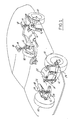
- a vehicle having an electrically powered active suspension will generally be equipped with a plurality of roadwheel and tyre assemblies, 10, which are controlled by means of suspension units 12.
- each front suspension unit is mounted resiliently between chassis 18 and a lower control arm, 24.
- Roadwheel and tyre assembly 10 is journalled upon spindle 20, which is pivotally attached to the outboard ends of control arms 22 and 24.
- the inboard ends of the control arms are pivotally attached to chassis 18.
- Figure 1 further shows the placement of four LVDT units, 14, in proximity to each of roadwheels 10.
- the LVDT units comprise height sensing means interposed between chassis 18 and roadwheel and tyre assemblies 10 such that vertical motion of the roadwheel with respect to chassis 18 will be accompanied by motion of the sliding sensor components with respect to each other.
- sensors 14 may be used to keep track of the vertical location of the roadwheel and tyre assemblies relative to the chassis of the vehicle.
- Other types of roadwheel vertical position sensors such as rotary Hall Effect or yet other types of linear or rotary resolver devices may alternatively be applied to a system according to the present invention. It will be further appreciated that a system according to the present invention could be employed not only with the parallel arm and MacPherson strut and beam axle combinations illustrated herein, but also with other types of suspensions.
- FIG. 2 illustrates details of the electrically powered suspension unit shown in Figure 1.
- lower casing 28 has a mounting eye, 30, for attaching the suspension unit to lower control arm 24 as shown in Figure 1.
- Lower casing 28 contains a clearance bore, 32, providing a space for ball screw 26 to run longitudinally.
- Ball screw 26 interacts with ball nut 34, which has two ball passages 38 formed therein.
- a plurality of balls 36 circulates through passages 38 as well as through return passage 40. Details of a plural lead ball nut screw actuator suitable for practising the present invention are shown in U.S. patent 4,211,125, which is hereby incorporated by reference into this specification.
- the ball nut and ball screw co-operating together, form a channel which may be likened to the channel formed by the inner and outer races of a bearing, with the balls providing rolling contact between the ball screw and ball nut. Accordingly, when the ball screw is rotated, the length between the upper and lower portions of suspension unit 12 will be either increased or decreased. It will be further appreciated that other types of gear or screw drives may be useful for practising the present invention.
- the ball screw of the suspension unit shown in Figure 2 is rigidly attached to armature 42 of an electric motor, 52, so that rotation of the motor will cause rotation of the ball screw and, concomitantly, extension or retraction of suspension unit 12.
- Armature 42 rotates in upper bearing 48 and lower bearing 50, which are shown as being of the angular contact type, but which could be configured according to other designs known to those skilled in the art and suggested by this disclosure.
- Motor stator 44 envelops a portion of armature 42 and is connected to power electronics 84 ( Figure 5).
- the motor shown in Figure 2 is of the brushless type, having electronic commutation. Accordingly, optical encoder 46 is provided for advising power electronics circuit 84 of the precise rotary location of armature 42.
- a magnetic position encoder is the model EK500 encoder by Electro-Kinesis, Inc.TM, a Superior Electric Company.
- a General Electric ECMTM six pole surface permanent magnet motor using MQ-3 Nd-B-Fe magnets may be useful for practising the present invention.
- the present invention may be practised with permanent magnet, induction, variable reluctance, or synchronous motors, or yet other types of motors suggested by this disclosure.
- These motors may employ a variety of architectures.
- the synchronous motor and one variety of the induction motor will employ a wound stator and a wound rotor for both the rotary and linear embodiments, either component of the permanent magnet motors may be wound, as may either component of the variable reluctance motor.
- variable reluctance motor With the variable reluctance motor, the winding is opposed by a slot/tooth element comprising the rotor or stator.
- the induction motor may comprise not only fully wound designs but also designs in which the stator is wound and the rotor or plunger comprises a known squirrel cage element.
- motor load cell 54 which is mounted between the end case of the motor and the upper portion of suspension unit 12. Load cell 54 bears upon isolator 55, which is interposed between chassis 18 and motor load cell 54.
- the suspension unit of Figure 2 has not only an electrically powered load bearing means but also a fluid powered load bearing means comprising a fluid spring mounted about the motor and gearset.
- the fluid spring comprises rolling lobe airspring 58, which interacts with piston 60, which is in turn attached to the lower end of lower casing 28.
- the upper end of rolling lobe air spring 58 is attached to upper housing 62. Load bearing forces generated by air spring 58 are thus transmitted into the lower casing 28 and upper housing 62. The amount of such force is sensed by means of pneumatic spring load cell 66, which is interposed between upper housing 62 and chassis 18.
- the two load cells 54 and 66 which are connected to system controller 80 ( Figure 5), allow system controller 80 to determine the load carrying forces generated by the pneumatic and electric devices so that the fraction of the total load which is carried by each of the load bearing means may be adjusted.
- means may be provided for monitoring the control currents supplied to the electric motor and combined with means for converting such currents into a signal having a value which is proportional to the force exerted by said motor.
- the load carrying force exerted by airspring 58 is proportional to the pressure of air contained within the airspring. Accordingly, the airspring is provided with air through valve 64 which is in turn connected with air compressor 90 ( Figure 5).
- Figure 3 illustrates an alternate construction for the strut portion of a suspension system according to the present invention.
- Figure 3 illustrates the well-known MacPherson construction in which the lower end of suspension unit 12 is rigidly attached to spindle 20 upon which roadwheel and tyre assembly 10 is journalled.
- Control arm 24 is pivotally attached between suspension unit 12 and chassis 18.
- the suspension unit of Figure 3 has a coil spring, 16, mounted about the electrically powered portion of the strut, which may comprise either a rotary or a linear electric motor as described herein. It is possible to apportion the load between the coil spring and the motor driven unit by changing the ride height of the vehicle.
- Figure 4 illustrates a linear motor incorporated into a suspension unit according to the present invention.
- the motor shown is an induction motor in which only plunger 68 is wound, with hollow stator 70 comprising a conductive metallic structure which carries induced currents. Force in an induction motor is caused by the interaction between an applied magnetic field in one member (in this case, the plunger), and currents induced in the conductor of a second member on the other side of a separating air gap.
- Plunger 68 is attached at its upper extremity to chassis 18 and comprises lamination packs, steel coils, magnet wire coils, end caps, and a shaft.
- the plunger is slidably carried within stator 70, which is attached to mounting eye 30, and which comprises a bimetallic tube, having an aluminium inner surface and a steel outer surface. The two sleeves are assembled and then the inner bore is honed for straightness.
- the suspension unit of Figure 4 further includes resolver 74, which keeps track of the position of the motor for commutation purposes.
- an air spring, 58 is included, as is valve 64 for admitting compressed air into the air spring.
- the suspension unit shown in Figure 4 may be integrated in the suspension shown in Figure 1 by substituting the linear device of Figure 4 for the rotary motor powered device of Figure 2.
- the plunger and resolver are each wired to system controller 80 and power electronics module 84.
- the linear and rotary motor embodiments disclosed herein may both be controlled according to a scheme set forth below.
- system controller 80 communicates with and is operatively connected with several of the other components of a system according to this invention. Accordingly, system controller 80 is interconnected with power electronics module 84, as well as with suspension units 12, accelerometers 82, height sensors 14, and air compressor 90.
- power electronics module 84 as well as with suspension units 12, accelerometers 82, height sensors 14, and air compressor 90.
- air compressor 90 and rolling lobe airspring 58 are merely intended to be exemplary of a class of devices comprising fluid power units. Other types of such units could be used in a system according to the present invention, including but not limited to hydro-pneumatic, or even low-powered hydraulic devices.
- System controller 80 comprises a microprocessor controller and appropriate input and output devices including analog to digital and digital to analog converters.
- the microprocessor preferably comprises a read only memory (ROM) for storing various constants and control programs for controlling the suspension system.
- the microprocessor further includes a central processing unit (CPU) for reading out control programs from the ROM so as to execute required operations, and a random access memory (RAM), which temporarily stores various data related to the operations to be executed within the CPU, and which allows the CPU to read out the data stored therein.
- the microprocessor further includes a clock generator which generates clock pulses in response to which the operations are executed in the microprocessor.
- At least one of the control programs stored within the ROM of system controller 80 comprises an outer loop control for determining the desired force from each suspension unit. Using information from the accelerometers, height sensors, and other vehicular sensors, the outer loop will calculate a desired force, F c , for each suspension unit.
- x1-x5 are non-dimensional representations of the vertical acceleration of the vehicle body or chassis: tyre deflection; the distance between the suspension jounce stops; and chassis pitch and roll, respectively
- Figure 7 shows various plots characterising operation of a system according to the present invention.
- Each of the plots in Figure 7 has been marked with an identification numeral in the range I-IV.
- Each of the plots is divided into a right and left section.
- the left sections correspond to a situation in which the roadwheel comes into contact with a bump protruding from the roadway surface.
- the right sections correspond to a situation in which the roadwheel initially falls into a depression such as a pothole, and then runs up out of the depression.
- Plot I illustrates roadwheel position, with the ordinate designating the ride height position. Accordingly, the ordinate is marked “jounce” to indicate movement of the roadwheel up into the chassis, and “rebound” to indicate movement of the roadwheel away from the chassis.
- the wheel will move upwardly i.e., in the jounce direction, so as to move closer to the chassis. This is shown in the left portion of I of Figure 7. Upward movement of the wheel will be accompanied by an increase in the load carrying force generated by fluid spring 58. This is shown in the left portion of plot II of Figure 7.
- plot III shows that electric motor force starts at the abscissa at zero force and builds along with the force build-up in air spring 58. Conversely, as the force build-up within airspring 58 decreases to the static load condition, the electric motor force decreases concomitantly. As is further shown in the left portion of plot III of Figure 7, the region under this plot illustrates energy absorbed by the motor of the suspension unit and energy supplied by the motor of the suspension unit to the electrical power source when the motor is operating in the regenerative mode.
- the motor is being operated as a generator to convert the energy which was stored in airspring 58 and in gravitational potential energy when the wheel moved in the jounce direction into electrical energy which may be either used immediately or stored for future use.
- This conversion of energy stored in the spring comprises the essence of regenerative operation for this embodiment of the present invention.
- the weight of the roadwheel and tyre assembly and the weight of the hardware which attaches the roadwheel to the suspension unit will provide a downwardly directed force which may be utilised to remove energy from the suspension system regeneratively.
- Plot IV of of the left portion of Figure 7 illustrates the net force on the vehicle's body or chassis resulting from operation of suspension unit 12 during the roadwheel's encounter with an object in the roadway. Note that the force line is almost flat, indicating that an almost constant force, approaching the static force required to support the vehicle, acts upon the vehicle body. As a result, the occupants of the vehicle will enjoy a smooth ride free from undesirable road inputs.
- plot I shows the roadwheel moving in the rebound direction and then back up into the nominal ride height position.
- the force developed by airspring 58 tracks the ride height excursion (plot II).
- electric motor force is shown in plot III. Note however, that the portions of plot III showing energy absorbing and regenerative operation are reversed in the left and right portions. This phenomenon occurs because as the roadwheel moves downwardly into the hole, the motor exerts a force in the upward direction; as a result, the motor is driven regeneratively.
- system controller 80 will measure a force increase by means of motor load cell 54 and pneumatic spring cell 66.
- the load cells will sense greater forces acting upon the chassis, with the forces being transmitted by the pneumatic and electric load bearing devices.
- system controller 80 Upon sensing increased loading, system controller 80 will give a command to power electronics module 84 to actuate suspension units 12 so as to counteract the force build-up produced within fluid spring 58 by lifting the roadwheel. Power will then be supplied to the suspension units by means of capacitor 86 which is operatively connected with power electronics module 84 ( Figure 5) and which is in turn supplied with power by means of alternator 88 which is driven by the engine of the vehicle.
- alternator 88 could be augmented by means of a storage battery.
- alternator 88 could be replaced entirely by means of a storage battery.
- capacitor 86 has been shown as comprising a single unit, for certain applications of a system according to the present invention it may be desirable to use a plurality of high volumetric efficiency capacitors, with one such capacitor located in proximity to each suspension unit.
- System controller 80 will be able to determine the relatively variant and relatively invariant components of the loads imposed upon suspension units 12 by tracking the load magnitude as a function of time. Once the invariant fraction of the load has been resolved, air spring 58 may be commanded to produce this portion of the load, thereby freeing the electric motor for the task of handling dynamic suspension loads.
- system controller 80 will give a signal to power electronics module 84 to cause the electric motor of the strut to counteract such force.
- a force command will be given to suspension unit 12, subject to feedback from height sensors 14 that an insufficient amount of stroke remains in the suspension unit.
- system controller 80 will give an artificial jounce bumper command to power electronics 84 so as to greatly decrease the amount of force developed by the motor, thereby preventing the suspension unit from crashing into the full jounce position.
- system controller 80 and power electronics module 84 together comprise means for producing force commands corresponding to the forces to be produced by each of the load bearing means and comparator means for comparing the commanded forces with the actual forces sensed by the load cells so as to produce an error signal which is then used to recalculate new force commands so as to cause the actual forces produced by the suspension unit to equal the commanded forces.
- the system controller may apply a proportional-integral-derivative (PID) type of control to the error signal to transform the error signal into a corrected force signal.
- PID proportional-integral-derivative
- the well-known PID control method generates an output signal which is proportional to the magnitude of the error signal and to its time derivative and time integral.
- the PID control method represents but one of several different control schemes which could be employed with a system according to the present invention.
- a modified control scheme will be employed for the purpose of damping such vertical motion of the chassis.
- This modified algorithm will operate by causing suspension units 12 to exert forces on the body which are in the opposite direction of the body velocity at any given moment. In other words, if the body is moving in the downward direction, the suspension units will be commanded to exert a force in an upward direction so as to damp the body movement.
- Figure 6 illustrates certain details of a power electronics module useful for implementing a system according to the present invention.
- Figure 6A illustrates additional details of the structure of Figure 6, including the structure of the field oriented controller contained in Figure 6.
- power electronics module 84 receives force commands, Fc, from system controller 80.
- the power electronics module is given the task of supplying the correct phase currents to motor 52, so as to produce the forces specified by system controller 80.
- summer or comparator 100 marks the point at which command force, F c , which is the commanded force from system controller 80, is added to or in other words, compared with F dev .
- F dev is the measured force output derived from load cells 54 and 66 or derived in part by the system controller, using motor current information.
- the output of comparator 100 is sent to field oriented controller 102, which will be described in detail with reference to Figure 6A.
- the purpose of field oriented controller 102 is to calculate appropriate phase currents to feed to each of the three phase legs 110 which supply the phase currents to motor 52.
- field oriented controller 102 also receives data from rotor position sensor 46, which in this case comprises the previously described optical encoder. Finally, field oriented controller 102 senses the currents in the individual motor windings. Although only the currents I A and I B are shown as being sensed directly, with the third current, I C , being derived from currents I A and I B by comparator 105 as the negative of the sum of I A and I B , those skilled in the art will appreciate in view of this disclosure that is possible to directly measure all three of the phase currents as an alternative to the use of comparator or summer 105.
- Field oriented controller 102 calculates the desired phase currents I A *, I B *, and I C *. These idealised phase currents are compared by means of comparators 104 to each of the measured phase currents I A , I B , and I C respectively. The error for each current is then fed to current mode controllers 106.
- the function of the current mode controllers is to switch phase currents on and off, provided a predetermined hysteretic current level has been satisfied. It has been determined that model CS320 current mode controllers by Cherry Semiconductor will be useful as device 106.
- the outputs of the current mode controllers are fed to drivers 108, which supply gate charges for the purpose of switching transistors S1-S6.
- Transistors S1 and S2, S3 and S4, S5 and S6, which are labelled 110 in Figure 6, comprise, respectively, phase legs for supplying three separate phase currents to motor 52.
- Each of transistors S1-S6 comprises an insulated gate bipolar transistor (IGBT).
- IGBT insulated gate bipolar transistor
- Phase currents I A , I B and I C are shown as entering field oriented controller 102 at combination sample and hold amplifier and analog to digital converters (SHA/ADC) 112.
- the digital equivalents of the phase currents are used at block 120 of Figure 6A in various equations for calculating I Q and I D , which are the quadrature and direct axis equivalent currents for motor 52.
- I Q is used further for calculating F′, which is the estimated developed force.
- the equation for F′ is shown in block 120.
- the measured force from the load cells may be entered by means of SHA/ADC 118.
- the equation calculation block shown at 120 in Figure 6A receives further inputs from optical encoder 46 or another type of motor position sensor in the form of r M which is fed to MBUS decoder device 114. Finally, force commands from system controller 80 are fed into calculational scheme by means of SHA/ADC 116.
- the computer calculates r E which is the electrical rotor angle corresponding to the mechanical rotor angle, r M , as well as I Q , I D , and F′, which have previously been discussed.
- computer compares I D to I D ′, which is set equal to zero by means of comparator 122, but only in the event that motor 52, in the rotating embodiment illustrated in Figure 2, is a permanent magnet motor. I D ′ could be non-zero for implementations such as with a linear induction motor.
- the result of the comparison, I DE is then modified by PID controller 124.
- This controller essentially comprises an integrator and a proportional multiplier.
- the desired current I D * is the output of PID controller 124. In an ideal situation it would be possible to perform the current comparison and tracking without using a PID compensator.
- the response to the phase currents is not instantaneous and the PID utilises the error so as to enhance the responsiveness of the system.
- the estimated developed force F′ is compared to the force command by comparator 128 and the error is fed through PID 130 and then converted to I Q * by means of a multiplication operation at block 132.
- PID 124 and PID 130 could be supplanted by other types of control strategies known in the art and suggested by this disclosure.
- a reverse transformation process translates I D * and I Q * into desired line currents I A *, I B * and I C *.
- digital to analog converters 134 are employed for converting digital signals I A *, I B * and I C * into analog signals for feeding to comparators or summers 104 ( Figure 6).
- comparators 104 and current mode controllers 106 comprise a current band or hysteresis controller relying on the feedback of the three stator currents to minimise introduction of DC currents in the motor. This will minimise torque pulsation in the suspension unit.
- a system according to present invention senses the load carrying force produced by each of the load bearing means employed therein, and determines force commands by maintaining the sum of the load carrying forces produced by the load bearing means at a value having a magnitude approximating that of the relatively invariant load component. These force commands will be distributed to various suspension units so that the desired load forces may be developed.
Landscapes
- Engineering & Computer Science (AREA)
- Mechanical Engineering (AREA)
- Vehicle Body Suspensions (AREA)
- Control Of Ac Motors In General (AREA)
Applications Claiming Priority (2)
| Application Number | Priority Date | Filing Date | Title |
|---|---|---|---|
| US25345688A | 1988-10-05 | 1988-10-05 | |
| US253456 | 1988-10-05 |
Publications (3)
| Publication Number | Publication Date |
|---|---|
| EP0363158A2 true EP0363158A2 (de) | 1990-04-11 |
| EP0363158A3 EP0363158A3 (de) | 1991-03-06 |
| EP0363158B1 EP0363158B1 (de) | 1995-03-08 |
Family
ID=22960341
Family Applications (1)
| Application Number | Title | Priority Date | Filing Date |
|---|---|---|---|
| EP19890310120 Expired - Lifetime EP0363158B1 (de) | 1988-10-05 | 1989-10-03 | Elektrisch angetriebene aktive Fahrzeugaufhängung |
Country Status (4)
| Country | Link |
|---|---|
| EP (1) | EP0363158B1 (de) |
| JP (1) | JPH02120113A (de) |
| CA (1) | CA1336616C (de) |
| DE (1) | DE68921534T2 (de) |
Cited By (35)
| Publication number | Priority date | Publication date | Assignee | Title |
|---|---|---|---|---|
| EP0436870A3 (en) * | 1990-01-08 | 1992-04-01 | General Electric Company | Dynamic vehicle suspension system including electronically commutated motor |
| EP0495565A3 (en) * | 1991-01-14 | 1992-12-02 | Ford Motor Company Limited | Fail-safe variable damping suspension for a motor vehicle |
| US5276621A (en) * | 1991-05-20 | 1994-01-04 | General Motors Corporation | Quarter car variable force suspension system control |
| US5434782A (en) * | 1991-05-20 | 1995-07-18 | General Motors Corporation | Suspension system state observer |
| US5475596A (en) * | 1991-05-20 | 1995-12-12 | General Motors Corporation | Full car semi-active suspension control based on quarter car control |
| US5491633A (en) * | 1991-05-20 | 1996-02-13 | General Motors Corporation | Position sensor for electromechanical suspension |
| DE19714565A1 (de) * | 1996-06-28 | 1998-01-08 | Mannesmann Sachs Ag | Stablisatoranordnung |
| WO1997026145A3 (en) * | 1996-01-19 | 1998-01-15 | Carlo Alberto Zenobi | Apparatus for regenerating energy from the dynamic interactions between ground and running vehicles |
| GB2347127A (en) * | 1999-02-10 | 2000-08-30 | Rover Group | An electric generator driven by a vehicle suspension |
| US6161844A (en) * | 1997-05-16 | 2000-12-19 | Conception Et Developpement Michelin S.A. | Suspension device comprising a spring corrector |
| WO2001002198A1 (en) * | 1999-07-05 | 2001-01-11 | Kinetic Developments Limited | Electromagnetic damper for vehicle suspension |
| DE10122542A1 (de) * | 2000-07-26 | 2002-02-07 | Continental Teves Ag & Co Ohg | Vorrichtung zur Regelung von Bewegungen des Aufbaus von Kraftfahrzeugen |
| EP1219476A1 (de) * | 2000-12-29 | 2002-07-03 | Mando Corporation | Motorgeregeltes Aufhängungssystem zum Regeln der Fahrzeughöhe und einer Dämpfungskraft |
| WO2004071793A1 (de) * | 2003-02-17 | 2004-08-26 | Bayerische Motoren Werke | Aktive fahrzeug-radaufhängung mit einem linearmotor |
| EP1681188A1 (de) * | 2005-01-14 | 2006-07-19 | Zf Friedrichshafen Ag | Verfahren zum Betrieb eines Federträgers mit elektrischer Federkraftverstellung |
| WO2008031649A1 (de) * | 2006-09-15 | 2008-03-20 | Continental Aktiengesellschaft | Luftfederbein |
| EP1985476A4 (de) * | 2006-02-16 | 2009-05-06 | Kayaba Industry Co Ltd | Elektromagnetische aufhängungsvorrichtung |
| EP1958800A3 (de) * | 2007-02-14 | 2009-12-02 | Audi Ag | Elektromechanische Stellvorrichtung für Radaufhängungen von Kraftfahrzeugen |
| WO2010027701A1 (en) * | 2008-09-08 | 2010-03-11 | Bose Corporation | Actuator with counter-rotating motors with linear output |
| EP1995090A3 (de) * | 2007-05-21 | 2010-11-03 | Aisin Seiki Kabushiki Kaisha | Aufhängungsvorrichtung |
| US8042658B2 (en) | 2006-10-11 | 2011-10-25 | Kayaba Industry Co., Ltd. | Suspension device |
| US20120133334A1 (en) * | 2009-02-23 | 2012-05-31 | Li-Tec Battery Gmbh | Method and charging apparatus for charging a motor vehicle battery |
| US20140297119A1 (en) * | 2013-03-15 | 2014-10-02 | Levant Power Corporation | Context aware active suspension control system |
| CN105035088A (zh) * | 2014-05-02 | 2015-11-11 | 福特全球技术公司 | 通过行车历史的道路粗糙度预瞄 |
| WO2016087171A1 (fr) * | 2014-12-03 | 2016-06-09 | IFP Energies Nouvelles | Systeme d'actionnement lineaire electrique equipe de moyens de stockage d'energie |
| US9597940B2 (en) | 2013-03-15 | 2017-03-21 | ClearMotion, Inc. | Active vehicle suspension |
| US9597939B2 (en) | 2008-04-17 | 2017-03-21 | ClearMotion, Inc. | Hydraulic energy transfer |
| US9694639B2 (en) | 2013-03-15 | 2017-07-04 | ClearMotion, Inc. | Distributed active suspension control system |
| US9702349B2 (en) | 2013-03-15 | 2017-07-11 | ClearMotion, Inc. | Active vehicle suspension system |
| US9702424B2 (en) | 2014-10-06 | 2017-07-11 | ClearMotion, Inc. | Hydraulic damper, hydraulic bump-stop and diverter valve |
| US9855814B2 (en) | 2013-04-23 | 2018-01-02 | ClearMotion, Inc. | Active suspension with structural actuator |
| CN110626180A (zh) * | 2019-02-27 | 2019-12-31 | 深圳市大可奇科技有限公司 | 车辆动力控制系统及方法 |
| EP3988353A1 (de) * | 2020-10-26 | 2022-04-27 | Haldex Brake Products AB | Fahrzeugaufhängungsvorrichtung |
| CN115803209A (zh) * | 2020-05-27 | 2023-03-14 | 马瑞利悬挂系统意大利公司 | 设置有悬架的车辆和用于控制这种悬架的机电旋转设备,以及用于控制车辆悬架的运动的方法 |
| CN117465180A (zh) * | 2023-10-31 | 2024-01-30 | 西南交通大学 | 面向驾乘体验提升的可调负刚度空簧总成及系统控制方法 |
Families Citing this family (7)
| Publication number | Priority date | Publication date | Assignee | Title |
|---|---|---|---|---|
| DE19916366A1 (de) * | 1999-04-13 | 2000-10-19 | Zahnradfabrik Friedrichshafen | Aktuator |
| DE19955410B4 (de) * | 1999-11-18 | 2011-05-05 | Bayerische Motoren Werke Aktiengesellschaft | Vorrichtung zur aktiven Federung eines Kraftfahrzeugrades an einem Fahrzeugaufbau |
| JP4142946B2 (ja) * | 2002-12-18 | 2008-09-03 | カヤバ工業株式会社 | 車両用電磁緩衝器 |
| JP4822756B2 (ja) * | 2005-07-26 | 2011-11-24 | カヤバ工業株式会社 | モータ駆動回路および電磁サスペンション装置 |
| JP4898163B2 (ja) * | 2005-07-26 | 2012-03-14 | カヤバ工業株式会社 | 電磁サスペンション装置 |
| JP5211017B2 (ja) * | 2009-11-13 | 2013-06-12 | トヨタ自動車株式会社 | 車両用サスペンション装置 |
| WO2023048970A1 (en) * | 2021-09-21 | 2023-03-30 | Bromden Ventures Llc | Suspension with air reservoir |
Family Cites Families (5)
| Publication number | Priority date | Publication date | Assignee | Title |
|---|---|---|---|---|
| GB1096497A (en) * | 1965-12-15 | 1967-12-29 | Moulton Development Ltd | Improvements in vehicle wheel suspension systems |
| GB1182272A (en) * | 1966-05-20 | 1970-02-25 | Lucas Industries Ltd | Rear Suspension Systems for Road Vehicles. |
| DE8222808U1 (de) * | 1982-08-12 | 1982-12-23 | Siemens AG, 1000 Berlin und 8000 München | Induktive Feder- und Dämpfervorrichtung |
| WO1984002886A1 (en) * | 1983-01-21 | 1984-08-02 | Lotus Car | Vehicle suspension system |
| DE3889329T2 (de) * | 1988-01-20 | 1994-11-17 | Moog Inc | Fahrzeugaufhängesystem und dessen betrieb. |
-
1989
- 1989-09-08 CA CA 610770 patent/CA1336616C/en not_active Expired - Fee Related
- 1989-09-20 JP JP1244898A patent/JPH02120113A/ja active Pending
- 1989-10-03 EP EP19890310120 patent/EP0363158B1/de not_active Expired - Lifetime
- 1989-10-03 DE DE1989621534 patent/DE68921534T2/de not_active Expired - Fee Related
Cited By (51)
| Publication number | Priority date | Publication date | Assignee | Title |
|---|---|---|---|---|
| EP0436870A3 (en) * | 1990-01-08 | 1992-04-01 | General Electric Company | Dynamic vehicle suspension system including electronically commutated motor |
| EP0495565A3 (en) * | 1991-01-14 | 1992-12-02 | Ford Motor Company Limited | Fail-safe variable damping suspension for a motor vehicle |
| US5276621A (en) * | 1991-05-20 | 1994-01-04 | General Motors Corporation | Quarter car variable force suspension system control |
| US5434782A (en) * | 1991-05-20 | 1995-07-18 | General Motors Corporation | Suspension system state observer |
| US5475596A (en) * | 1991-05-20 | 1995-12-12 | General Motors Corporation | Full car semi-active suspension control based on quarter car control |
| US5491633A (en) * | 1991-05-20 | 1996-02-13 | General Motors Corporation | Position sensor for electromechanical suspension |
| WO1997026145A3 (en) * | 1996-01-19 | 1998-01-15 | Carlo Alberto Zenobi | Apparatus for regenerating energy from the dynamic interactions between ground and running vehicles |
| US6111375A (en) * | 1996-01-19 | 2000-08-29 | Zenobi; Carlo Alberto | Apparatus for regenerating energy from the dynamic interactions between ground and running vehicles |
| DE19714565A1 (de) * | 1996-06-28 | 1998-01-08 | Mannesmann Sachs Ag | Stablisatoranordnung |
| DE19714565C2 (de) * | 1996-06-28 | 1998-05-14 | Mannesmann Sachs Ag | Stablisatoranordnung |
| US6161844A (en) * | 1997-05-16 | 2000-12-19 | Conception Et Developpement Michelin S.A. | Suspension device comprising a spring corrector |
| GB2347127A (en) * | 1999-02-10 | 2000-08-30 | Rover Group | An electric generator driven by a vehicle suspension |
| WO2001002198A1 (en) * | 1999-07-05 | 2001-01-11 | Kinetic Developments Limited | Electromagnetic damper for vehicle suspension |
| DE10122542A1 (de) * | 2000-07-26 | 2002-02-07 | Continental Teves Ag & Co Ohg | Vorrichtung zur Regelung von Bewegungen des Aufbaus von Kraftfahrzeugen |
| DE10122542B4 (de) * | 2000-07-26 | 2009-12-03 | Continental Teves Ag & Co. Ohg | Vorrichtung zur Regelung von Bewegungen des Aufbaus von Kraftfahrzeugen sowie Federbein für Kraftfahrzeuge |
| DE10122542C5 (de) * | 2000-07-26 | 2017-01-12 | Continental Teves Ag & Co. Ohg | Vorrichtung zur Regelung von Bewegungen des Aufbaus von Kraftfahrzeugen sowie Federbein für Kraftfahrzeuge |
| EP1219476A1 (de) * | 2000-12-29 | 2002-07-03 | Mando Corporation | Motorgeregeltes Aufhängungssystem zum Regeln der Fahrzeughöhe und einer Dämpfungskraft |
| WO2004071793A1 (de) * | 2003-02-17 | 2004-08-26 | Bayerische Motoren Werke | Aktive fahrzeug-radaufhängung mit einem linearmotor |
| EP1681188A1 (de) * | 2005-01-14 | 2006-07-19 | Zf Friedrichshafen Ag | Verfahren zum Betrieb eines Federträgers mit elektrischer Federkraftverstellung |
| EP1985476A4 (de) * | 2006-02-16 | 2009-05-06 | Kayaba Industry Co Ltd | Elektromagnetische aufhängungsvorrichtung |
| WO2008031649A1 (de) * | 2006-09-15 | 2008-03-20 | Continental Aktiengesellschaft | Luftfederbein |
| US8042658B2 (en) | 2006-10-11 | 2011-10-25 | Kayaba Industry Co., Ltd. | Suspension device |
| EP1958800A3 (de) * | 2007-02-14 | 2009-12-02 | Audi Ag | Elektromechanische Stellvorrichtung für Radaufhängungen von Kraftfahrzeugen |
| EP1995090A3 (de) * | 2007-05-21 | 2010-11-03 | Aisin Seiki Kabushiki Kaisha | Aufhängungsvorrichtung |
| US9597939B2 (en) | 2008-04-17 | 2017-03-21 | ClearMotion, Inc. | Hydraulic energy transfer |
| US7963529B2 (en) | 2008-09-08 | 2011-06-21 | Bose Corporation | Counter-rotating motors with linear output |
| CN102076990B (zh) * | 2008-09-08 | 2013-12-11 | 伯斯有限公司 | 具有线性输出的反向旋转电机 |
| RU2471646C2 (ru) * | 2008-09-08 | 2013-01-10 | Боуз Корпорейшн | Вращающиеся в противоположных направлениях двигатели с линейным выходом |
| WO2010027701A1 (en) * | 2008-09-08 | 2010-03-11 | Bose Corporation | Actuator with counter-rotating motors with linear output |
| US20120133334A1 (en) * | 2009-02-23 | 2012-05-31 | Li-Tec Battery Gmbh | Method and charging apparatus for charging a motor vehicle battery |
| US9702349B2 (en) | 2013-03-15 | 2017-07-11 | ClearMotion, Inc. | Active vehicle suspension system |
| US9809078B2 (en) | 2013-03-15 | 2017-11-07 | ClearMotion, Inc. | Multi-path fluid diverter valve |
| US9440507B2 (en) * | 2013-03-15 | 2016-09-13 | Levant Power Corporation | Context aware active suspension control system |
| US9550404B2 (en) | 2013-03-15 | 2017-01-24 | Levant Power Corporation | Active suspension with on-demand energy flow |
| US9597940B2 (en) | 2013-03-15 | 2017-03-21 | ClearMotion, Inc. | Active vehicle suspension |
| US9707814B2 (en) | 2013-03-15 | 2017-07-18 | ClearMotion, Inc. | Active stabilization system for truck cabins |
| US9676244B2 (en) | 2013-03-15 | 2017-06-13 | ClearMotion, Inc. | Integrated active suspension smart valve |
| US9694639B2 (en) | 2013-03-15 | 2017-07-04 | ClearMotion, Inc. | Distributed active suspension control system |
| US20140297119A1 (en) * | 2013-03-15 | 2014-10-02 | Levant Power Corporation | Context aware active suspension control system |
| US9855814B2 (en) | 2013-04-23 | 2018-01-02 | ClearMotion, Inc. | Active suspension with structural actuator |
| CN105035088A (zh) * | 2014-05-02 | 2015-11-11 | 福特全球技术公司 | 通过行车历史的道路粗糙度预瞄 |
| US9702424B2 (en) | 2014-10-06 | 2017-07-11 | ClearMotion, Inc. | Hydraulic damper, hydraulic bump-stop and diverter valve |
| WO2016087171A1 (fr) * | 2014-12-03 | 2016-06-09 | IFP Energies Nouvelles | Systeme d'actionnement lineaire electrique equipe de moyens de stockage d'energie |
| US10316596B2 (en) * | 2014-12-03 | 2019-06-11 | IFP Energies Nouvelles | Electric linear actuation system equipped with energy storage |
| CN110626180A (zh) * | 2019-02-27 | 2019-12-31 | 深圳市大可奇科技有限公司 | 车辆动力控制系统及方法 |
| CN115803209A (zh) * | 2020-05-27 | 2023-03-14 | 马瑞利悬挂系统意大利公司 | 设置有悬架的车辆和用于控制这种悬架的机电旋转设备,以及用于控制车辆悬架的运动的方法 |
| EP4157654A1 (de) * | 2020-05-27 | 2023-04-05 | Marelli Suspension Systems Italy S.p.A. | Fahrzeug mit aufhängung und elektromechanische drehvorrichtung zur steuerung solch einer aufhängung und verfahren zur steuerung der bewegung einer fahrzeugaufhängung |
| US12291067B2 (en) | 2020-05-27 | 2025-05-06 | Marelli Suspension Systems Italy S.P.A. | Vehicle provided with a suspension and an electromechanical rotary device for controlling the suspension, and method for controlling motion of a vehicle suspension |
| EP3988353A1 (de) * | 2020-10-26 | 2022-04-27 | Haldex Brake Products AB | Fahrzeugaufhängungsvorrichtung |
| CN117465180A (zh) * | 2023-10-31 | 2024-01-30 | 西南交通大学 | 面向驾乘体验提升的可调负刚度空簧总成及系统控制方法 |
| CN117465180B (zh) * | 2023-10-31 | 2024-05-17 | 西南交通大学 | 面向驾乘体验提升的可调负刚度空簧总成及系统控制方法 |
Also Published As
| Publication number | Publication date |
|---|---|
| CA1336616C (en) | 1995-08-08 |
| EP0363158B1 (de) | 1995-03-08 |
| DE68921534T2 (de) | 1995-07-20 |
| JPH02120113A (ja) | 1990-05-08 |
| EP0363158A3 (de) | 1991-03-06 |
| DE68921534D1 (de) | 1995-04-13 |
Similar Documents
| Publication | Publication Date | Title |
|---|---|---|
| EP0363158B1 (de) | Elektrisch angetriebene aktive Fahrzeugaufhängung | |
| US5060959A (en) | Electrically powered active suspension for a vehicle | |
| US5027048A (en) | Field oriented motor controller for electrically powered active suspension for a vehicle | |
| US8285448B2 (en) | Suspension system for vehicle | |
| EP2262654B1 (de) | Fahrzeugradaufhängung mit elektromagnetischem stellglied | |
| EP1894756B1 (de) | Fahrzeugaufhängungssystem | |
| US7938410B2 (en) | Suspension system for vehicle | |
| US4981309A (en) | Electromechanical transducing along a path | |
| JP3722128B2 (ja) | 車両用電磁サスペンション装置と車両用電磁サスペンション装置のモータ制御方法 | |
| KR20200119905A (ko) | 수요 공급식 에너지를 갖는 액티브 현가장치 | |
| JP2008222112A (ja) | エネルギー回生ダンパ装置、および、エネルギー回生ダンパシステム | |
| JP5387857B2 (ja) | 車両用サスペンション装置 | |
| JP4296110B2 (ja) | アクティブサスペンション | |
| JP4142551B2 (ja) | 車両懸架装置 | |
| JP2011162067A (ja) | 減衰力制御装置 | |
| JP4775250B2 (ja) | 車両用サスペンションシステム | |
| US12489384B2 (en) | Control device, vehicle behavior control device, and force generation mechanism system | |
| JP4888078B2 (ja) | 車両用サスペンションシステム | |
| JP2008162333A (ja) | 車両用サスペンションシステム | |
| JP2008114745A (ja) | 車両用サスペンションシステム | |
| JP2011020487A (ja) | ショックアブソーバ装置 | |
| JP2008222023A (ja) | 車両用電磁式アブソーバシステム |
Legal Events
| Date | Code | Title | Description |
|---|---|---|---|
| PUAI | Public reference made under article 153(3) epc to a published international application that has entered the european phase |
Free format text: ORIGINAL CODE: 0009012 |
|
| AK | Designated contracting states |
Kind code of ref document: A2 Designated state(s): DE FR GB |
|
| PUAL | Search report despatched |
Free format text: ORIGINAL CODE: 0009013 |
|
| AK | Designated contracting states |
Kind code of ref document: A3 Designated state(s): DE FR GB |
|
| 17P | Request for examination filed |
Effective date: 19910821 |
|
| 17Q | First examination report despatched |
Effective date: 19920914 |
|
| GRAA | (expected) grant |
Free format text: ORIGINAL CODE: 0009210 |
|
| AK | Designated contracting states |
Kind code of ref document: B1 Designated state(s): DE FR GB |
|
| REF | Corresponds to: |
Ref document number: 68921534 Country of ref document: DE Date of ref document: 19950413 |
|
| ET | Fr: translation filed | ||
| REG | Reference to a national code |
Ref country code: GB Ref legal event code: 746 Effective date: 19950920 |
|
| PLBE | No opposition filed within time limit |
Free format text: ORIGINAL CODE: 0009261 |
|
| STAA | Information on the status of an ep patent application or granted ep patent |
Free format text: STATUS: NO OPPOSITION FILED WITHIN TIME LIMIT |
|
| REG | Reference to a national code |
Ref country code: FR Ref legal event code: D6 |
|
| 26N | No opposition filed | ||
| REG | Reference to a national code |
Ref country code: FR Ref legal event code: TP Ref country code: FR Ref legal event code: CD |
|
| REG | Reference to a national code |
Ref country code: GB Ref legal event code: IF02 |
|
| PGFP | Annual fee paid to national office [announced via postgrant information from national office to epo] |
Ref country code: GB Payment date: 20030929 Year of fee payment: 15 |
|
| PGFP | Annual fee paid to national office [announced via postgrant information from national office to epo] |
Ref country code: FR Payment date: 20031009 Year of fee payment: 15 |
|
| PGFP | Annual fee paid to national office [announced via postgrant information from national office to epo] |
Ref country code: DE Payment date: 20031010 Year of fee payment: 15 |
|
| PG25 | Lapsed in a contracting state [announced via postgrant information from national office to epo] |
Ref country code: GB Free format text: LAPSE BECAUSE OF NON-PAYMENT OF DUE FEES Effective date: 20041003 |
|
| PG25 | Lapsed in a contracting state [announced via postgrant information from national office to epo] |
Ref country code: DE Free format text: LAPSE BECAUSE OF NON-PAYMENT OF DUE FEES Effective date: 20050503 |
|
| GBPC | Gb: european patent ceased through non-payment of renewal fee |
Effective date: 20041003 |
|
| PG25 | Lapsed in a contracting state [announced via postgrant information from national office to epo] |
Ref country code: FR Free format text: LAPSE BECAUSE OF NON-PAYMENT OF DUE FEES Effective date: 20050630 |
|
| REG | Reference to a national code |
Ref country code: FR Ref legal event code: ST |