EP0363226A2 - Montage de démodulation cohérente pour utilisation dans un système de communication numérique - Google Patents
Montage de démodulation cohérente pour utilisation dans un système de communication numérique Download PDFInfo
- Publication number
- EP0363226A2 EP0363226A2 EP89310300A EP89310300A EP0363226A2 EP 0363226 A2 EP0363226 A2 EP 0363226A2 EP 89310300 A EP89310300 A EP 89310300A EP 89310300 A EP89310300 A EP 89310300A EP 0363226 A2 EP0363226 A2 EP 0363226A2
- Authority
- EP
- European Patent Office
- Prior art keywords
- local oscillator
- output
- signal
- frequency
- incoming
- Prior art date
- Legal status (The legal status is an assumption and is not a legal conclusion. Google has not performed a legal analysis and makes no representation as to the accuracy of the status listed.)
- Granted
Links
Images



Classifications
-
- H—ELECTRICITY
- H03—ELECTRONIC CIRCUITRY
- H03L—AUTOMATIC CONTROL, STARTING, SYNCHRONISATION OR STABILISATION OF GENERATORS OF ELECTRONIC OSCILLATIONS OR PULSES
- H03L7/00—Automatic control of frequency or phase; Synchronisation
- H03L7/06—Automatic control of frequency or phase; Synchronisation using a reference signal applied to a frequency- or phase-locked loop
- H03L7/08—Details of the phase-locked loop
- H03L7/085—Details of the phase-locked loop concerning mainly the frequency- or phase-detection arrangement including the filtering or amplification of its output signal
- H03L7/087—Details of the phase-locked loop concerning mainly the frequency- or phase-detection arrangement including the filtering or amplification of its output signal using at least two phase detectors or a frequency and phase detector in the loop
-
- H—ELECTRICITY
- H03—ELECTRONIC CIRCUITRY
- H03D—DEMODULATION OR TRANSFERENCE OF MODULATION FROM ONE CARRIER TO ANOTHER
- H03D1/00—Demodulation of amplitude-modulated oscillations
- H03D1/22—Homodyne or synchrodyne circuits
- H03D1/2245—Homodyne or synchrodyne circuits using two quadrature channels
- H03D1/2254—Homodyne or synchrodyne circuits using two quadrature channels and a phase locked loop
-
- H—ELECTRICITY
- H03—ELECTRONIC CIRCUITRY
- H03L—AUTOMATIC CONTROL, STARTING, SYNCHRONISATION OR STABILISATION OF GENERATORS OF ELECTRONIC OSCILLATIONS OR PULSES
- H03L7/00—Automatic control of frequency or phase; Synchronisation
- H03L7/06—Automatic control of frequency or phase; Synchronisation using a reference signal applied to a frequency- or phase-locked loop
- H03L7/08—Details of the phase-locked loop
- H03L7/085—Details of the phase-locked loop concerning mainly the frequency- or phase-detection arrangement including the filtering or amplification of its output signal
- H03L7/093—Details of the phase-locked loop concerning mainly the frequency- or phase-detection arrangement including the filtering or amplification of its output signal using special filtering or amplification characteristics in the loop
Definitions
- This invention relates generally to a coherent demodulating arrangement for use in a digital radio communications system, and more specifically to such a demodulating arrangement by which a high quality baseband signal can be obtained even if a modulated incoming signal deviates in frequency.
- coherent demodulating arrangements are used to detect a baseband signal through multiplication of a digitally modulated incoming IF (Intermediate Frequency) signal and a reproduced carrier signal.
- the reproduction of a carrier signal is implemented by a phase-locked loop using a modulated baseband signal.
- an incoming modulated IF signal is applied via an input terminal 10 to a noncoherent demodulator 12, which also receives an output of a local oscillator 14.
- the frequency of the output of the oscillator 14 is previously set to the frequency of the incoming modulated IF signal.
- Term "noncoherent" in this specification implies that there exists no frequency or phase synchronization between the local oscillator 14 and the received IF signal.
- the output of the noncoherent demodulator 12 is, in most cases, not equal to a baseband signal but is similar thereto, and is applied to a coherent demodulator 16.
- the coherent demodulator 16 forms part of a phase-locked loop 18 which, in addition to the coherent demodulator 16, comprises a channel filter 20, a phase detector 22, a loop filter 24 and a voltage controlled oscillator (VCO) 26.
- VCO voltage controlled oscillator
- the coherent demodulator 16 receives a reproduced carrier wave from the VCO 26 and performs multiplication between the output of the unit 12 and the reproduced carrier wave.
- the output of the coherent demodulator 16 takes the form of a baseband signal which is applied to the phase detector 22 via the channel filter 20 which in this case exhibits a low-pass characteristics.
- the output of the coherent demodulator shown in Fig. 1, is derived from the channel filter 20. Since the coherent demodulator 16 precedes the channel filter 20, there is no degradation of signal wave even in the case of frequency deviation of incoming IF signal due to doppler shift in a satellite communications system, for example. However, the Fig. 1 arrangement has encountered the problem that the frequency response of the phase-locked loop 18 is undesirably lowered due to delay of signal transmission in the channel filter 20.
- Fig. 2 In order to overcome this problem, a second prior art, shown in Fig. 2, has been proposed.
- the arrangement of Fig. 2 is basically identical to that of Fig. 1 and differs only in that the coherent demodulator 16 is preceded by the channel filter 20. This overcomes the aforesaid lowering of the response of the phase-locked loop.
- the frequency of the local oscillator 14 is fixed to that of the incoming IF signal, when the frequency deviation occurs in the incoming IF signal, the output of the noncoherent demodulator 12 is apt to contain frequency components which are out of the passband of the filter 20. This induces the situation wherein means that the wave shape of the output signal of the channel filter 20 is degraded and causes intersymbol interference.
- the prior art shown in Fig. 2 cannot be relied upon to provide high quality demodulated signals under all circumstances.
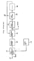
- One aspect of this invention takes the form of an arrangement for coherently demodulating an incoming IF signal in a digital radio communications system, comprising: a local oscillator, the output frequency of the local oscillator being controllable; a quasi-coherent demodulator coupled to receive the incoming IF signal and the output of the local oscillator; a channel filter coupled to receive the output of the quasi-coherent demodulator; a coherent demodulator coupled to receive the output of the channel filter and a reproduced carrier, the coherent demodulator outputting a baseband signal; a phase detector for detecting a phase difference between the baseband signal and the reproduced carrier; a loop filter coupled to receive the output of the phase detector; a voltage controlled oscillator coupled to receive the output of the loop filter and generating the reproduced carrier which is applied to the phase detector; and a local oscillator controller provided between the loop filter and the local oscillator.
- Fig. 3 illustrates the first embodiment of this invention.
- the difference between the arrangements of Figs. 2 and 3 comes in that the latter arrangement is provided with a controllable local oscillator 32 whose output frequency is varied by a local oscillator controller 30, and in that the output of the local oscillator 30 is applied to a quasi-coherent demodulator 34.
- the incoming modulated IF signal (phase angle: ⁇ i , angular frequency:Wi) is applied via the input terminal 10 to the quasi-coherent demodulator 34, which also receives the output of the local oscillator 32 (phase angle: ⁇ o , angular frequency:Wo).
- the frequency of the output of the oscillator 32 is controlled to fall within a predetermined frequency range whose center frequency coincides with a nominal frequency of the incoming IF signal.
- the frequency of the output of the oscillator 32 is controlled such that the difference between the angular frequencies Wi and Wo is within a predetermined range defined by ⁇ Rw.
- the output of the quasi-coherent demodulator 34 is, in most cases, exactly not equal to a baseband signal but is similar thereto, and is applied to the coherent demodulator 16 via the channel filter 20.
- the coherent demodulator 16 also receives a recovered carrier wave (phase angle: ⁇ v ) from the VCO 26 and synchronously demodulates the output of the channel filter 20 using the reproduced carrier wave.
- the output L is applied to the local oscillator controller 30 which has the two threshold levels: +Rw and -Rw.
- the local oscillator controller 30 If the output L exceeds the upper threshold level (+Rw), the local oscillator controller 30 outputs such a control signal which reduces the frequency difference (Wi - Wo). Therefore, the output frequency of the local oscillator 32 is controlled such that the output L of the loop filter 24 is located between +Rw and -Rw. On the other hand, in the event that the output L does not reach the lower threshold level (-Rw), the controller 30 outputs such a control signal which causes the frequency difference (Wi - Wo) to increase. As a consequence, the frequency of the output of the local oscillator 32 is controlled such that the output L falls within the range defined by ⁇ Rw.
- the frequency of the local oscillator 32 is automatically controlled such that the output of the quasi-coherent demodulator 34 falls within the passband of the channel filter 20.
- FIG. 4 wherein a second embodiment of the present invention is shown.
- This embodiment differs from the first one in that an analog-to-digital (A/D) converter 40 is provided between the quasi-coherent demodulator 34 and the channel filter 20, and in that a digital-to-analog (D/A) converter 42 is provided between the local oscillator controller 30 and the local oscillator 32.
- A/D analog-to-digital
- D/A digital-to-analog
Landscapes
- Engineering & Computer Science (AREA)
- Power Engineering (AREA)
- Digital Transmission Methods That Use Modulated Carrier Waves (AREA)
- Optical Communication System (AREA)
Applications Claiming Priority (2)
| Application Number | Priority Date | Filing Date | Title |
|---|---|---|---|
| JP253344/88 | 1988-10-07 | ||
| JP63253344A JPH0787476B2 (ja) | 1988-10-07 | 1988-10-07 | 復調装置 |
Publications (3)
| Publication Number | Publication Date |
|---|---|
| EP0363226A2 true EP0363226A2 (fr) | 1990-04-11 |
| EP0363226A3 EP0363226A3 (fr) | 1991-03-27 |
| EP0363226B1 EP0363226B1 (fr) | 1994-12-14 |
Family
ID=17250024
Family Applications (1)
| Application Number | Title | Priority Date | Filing Date |
|---|---|---|---|
| EP89310300A Expired - Lifetime EP0363226B1 (fr) | 1988-10-07 | 1989-10-09 | Montage de démodulation cohérente pour utilisation dans un système de communication numérique |
Country Status (5)
| Country | Link |
|---|---|
| US (1) | US5128626A (fr) |
| EP (1) | EP0363226B1 (fr) |
| JP (1) | JPH0787476B2 (fr) |
| AU (1) | AU611327B2 (fr) |
| DE (1) | DE68919984T2 (fr) |
Cited By (1)
| Publication number | Priority date | Publication date | Assignee | Title |
|---|---|---|---|---|
| US6778317B1 (en) * | 2003-02-19 | 2004-08-17 | The Aerospace Corporation | Optical fiber quadrature demodulator |
Families Citing this family (13)
| Publication number | Priority date | Publication date | Assignee | Title |
|---|---|---|---|---|
| US5260975A (en) * | 1989-10-23 | 1993-11-09 | Nippon Telegraph And Telephone Corporation | Digital demodulator |
| JPH0456443A (ja) * | 1990-06-26 | 1992-02-24 | Sony Corp | 局部発振装置 |
| JPH0834486B2 (ja) * | 1990-09-13 | 1996-03-29 | 松下電器産業株式会社 | データ伝送装置 |
| FR2672454B1 (fr) * | 1991-01-31 | 1994-10-07 | Alcatel Telspace | Procede de demodulation coherente pour modulation a deplacement de phase et dispositif de mise en óoeuvre de ce procede. |
| JP3132068B2 (ja) * | 1991-08-28 | 2001-02-05 | 日本電気株式会社 | 自動周波数制御装置 |
| US5282227A (en) * | 1992-05-21 | 1994-01-25 | The Titan Corporation | Communication signal detection and acquisition |
| JP2912791B2 (ja) * | 1993-06-01 | 1999-06-28 | 松下電器産業株式会社 | 高周波受信装置 |
| US5748049A (en) * | 1994-11-23 | 1998-05-05 | Anadigics, Inc. | Multi-frequency local oscillators |
| SE504341C2 (sv) * | 1995-05-22 | 1997-01-20 | Ericsson Telefon Ab L M | Förfarande och anordning vid fasmodulerade signaler |
| JP2000278341A (ja) * | 1999-03-25 | 2000-10-06 | Sanyo Electric Co Ltd | 直交位相復調回路 |
| DE10251309B3 (de) * | 2002-11-04 | 2004-04-29 | Advanced Micro Devices, Inc., Sunnyvale | Kohärente und nichtkohärente Datenpfadaufspaltung in Empfängern für eine verbesserte Synchronisierung |
| RU2263406C2 (ru) * | 2003-07-14 | 2005-10-27 | Федеральное государственное унитарное предприятие "Ростовский-на-Дону научно-исследовательский институт радиосвязи" (ФГУП "РНИИРС") | Способ автоматизированного мониторинга систем радиосвязи |
| US20050100344A1 (en) * | 2003-11-06 | 2005-05-12 | Hogan Josh N. | System for coherent optical communication |
Family Cites Families (5)
| Publication number | Priority date | Publication date | Assignee | Title |
|---|---|---|---|---|
| US3371281A (en) * | 1963-10-24 | 1968-02-27 | Gen Electric | Frequency modulation receiver combining frequency feedback and synchronous detection |
| JPS5586212A (en) * | 1978-12-22 | 1980-06-28 | Sony Corp | Frequency tracking circuit |
| KR900000464B1 (ko) * | 1984-10-05 | 1990-01-30 | 가부시기가이샤 히다찌세이사꾸쇼 | 복조 회로 |
| EP0235264A4 (fr) * | 1985-09-03 | 1990-02-26 | Motorola Inc | Recepteur de frequence radio numerique. |
| EP0297774B1 (fr) * | 1987-06-30 | 1994-06-08 | Nec Corporation | Démodulateur contrôlé en phase pour système de communication numérique |
-
1988
- 1988-10-07 JP JP63253344A patent/JPH0787476B2/ja not_active Expired - Lifetime
-
1989
- 1989-10-09 AU AU42715/89A patent/AU611327B2/en not_active Expired
- 1989-10-09 DE DE68919984T patent/DE68919984T2/de not_active Expired - Lifetime
- 1989-10-09 EP EP89310300A patent/EP0363226B1/fr not_active Expired - Lifetime
-
1991
- 1991-05-28 US US07/705,747 patent/US5128626A/en not_active Expired - Lifetime
Cited By (1)
| Publication number | Priority date | Publication date | Assignee | Title |
|---|---|---|---|---|
| US6778317B1 (en) * | 2003-02-19 | 2004-08-17 | The Aerospace Corporation | Optical fiber quadrature demodulator |
Also Published As
| Publication number | Publication date |
|---|---|
| EP0363226A3 (fr) | 1991-03-27 |
| EP0363226B1 (fr) | 1994-12-14 |
| JPH0787476B2 (ja) | 1995-09-20 |
| JPH02100545A (ja) | 1990-04-12 |
| US5128626A (en) | 1992-07-07 |
| DE68919984D1 (de) | 1995-01-26 |
| DE68919984T2 (de) | 1995-07-20 |
| AU611327B2 (en) | 1991-06-06 |
| AU4271589A (en) | 1990-04-12 |
Similar Documents
| Publication | Publication Date | Title |
|---|---|---|
| EP0363226B1 (fr) | Montage de démodulation cohérente pour utilisation dans un système de communication numérique | |
| US5235424A (en) | Automatic gain control system for a high definition television signal receiver | |
| CA2296855C (fr) | Appareil de detection et de demodulation de signaux de televisions numeriques | |
| US4142155A (en) | Diversity system | |
| JP3173788B2 (ja) | デジタル伝送装置および直接変換レシーバ | |
| CA1303691C (fr) | Boucle a phase asservie a restitution de porteuse | |
| US4853642A (en) | Phase controlled demodulator for digital communications system | |
| EP0373517B1 (fr) | Commande de fréquence automatique numérique pour ondes sinusoidales pures | |
| US4993048A (en) | Self-clocking system | |
| CA2048933A1 (fr) | Dispositif d'extraction de porteuse pour systeme de communication numerique a satellite | |
| US4517531A (en) | Carrier wave reproducing circuit in synchronized detection system of medium speed facsimile | |
| US4827488A (en) | Demodulator for PSK-modulated signals | |
| US6448861B2 (en) | PLL controller, method of PLL control, and limiter | |
| CA2065610C (fr) | Recepteur de signaux modules par deplacement de frequence | |
| US5373247A (en) | Automatic frequency control method and circuit for correcting an error between a received carrier frequency and a local frequency | |
| CA2102108C (fr) | Methode et appareil compensateur de phase | |
| EP0497801B1 (fr) | Boucle a verrouillage de phase servant a produire une porteuse de reference pour un detecteur coherent | |
| EP0208284B1 (fr) | Démodulateur capable d'éviter une démodulation anormale | |
| CA1283956C (fr) | Circuit de synchronisation d'horloge comportant un oscillateur commande par tension | |
| EP0064728B1 (fr) | Modulateur numérique de phases multiples | |
| US5881111A (en) | Frequency sweep circuit | |
| JP3801727B2 (ja) | 自動周波数制御回路 | |
| AU3518799A (en) | Demodulator circuits | |
| JPS644386B2 (fr) | ||
| JPS5937715A (ja) | 位相同期復調回路 |
Legal Events
| Date | Code | Title | Description |
|---|---|---|---|
| PUAI | Public reference made under article 153(3) epc to a published international application that has entered the european phase |
Free format text: ORIGINAL CODE: 0009012 |
|
| 17P | Request for examination filed |
Effective date: 19891017 |
|
| AK | Designated contracting states |
Kind code of ref document: A2 Designated state(s): DE FR GB NL |
|
| PUAL | Search report despatched |
Free format text: ORIGINAL CODE: 0009013 |
|
| AK | Designated contracting states |
Kind code of ref document: A3 Designated state(s): DE FR GB NL |
|
| 17Q | First examination report despatched |
Effective date: 19940208 |
|
| GRAA | (expected) grant |
Free format text: ORIGINAL CODE: 0009210 |
|
| AK | Designated contracting states |
Kind code of ref document: B1 Designated state(s): DE FR GB NL |
|
| REF | Corresponds to: |
Ref document number: 68919984 Country of ref document: DE Date of ref document: 19950126 |
|
| ET | Fr: translation filed | ||
| PLBE | No opposition filed within time limit |
Free format text: ORIGINAL CODE: 0009261 |
|
| STAA | Information on the status of an ep patent application or granted ep patent |
Free format text: STATUS: NO OPPOSITION FILED WITHIN TIME LIMIT |
|
| 26N | No opposition filed | ||
| REG | Reference to a national code |
Ref country code: GB Ref legal event code: IF02 |
|
| PGFP | Annual fee paid to national office [announced via postgrant information from national office to epo] |
Ref country code: DE Payment date: 20081014 Year of fee payment: 20 Ref country code: NL Payment date: 20081015 Year of fee payment: 20 |
|
| PGFP | Annual fee paid to national office [announced via postgrant information from national office to epo] |
Ref country code: FR Payment date: 20081014 Year of fee payment: 20 |
|
| PGFP | Annual fee paid to national office [announced via postgrant information from national office to epo] |
Ref country code: GB Payment date: 20081008 Year of fee payment: 20 |
|
| REG | Reference to a national code |
Ref country code: GB Ref legal event code: PE20 Expiry date: 20091008 |
|
| NLV7 | Nl: ceased due to reaching the maximum lifetime of a patent | ||
| PG25 | Lapsed in a contracting state [announced via postgrant information from national office to epo] |
Ref country code: NL Free format text: LAPSE BECAUSE OF EXPIRATION OF PROTECTION Effective date: 20091009 |
|
| PG25 | Lapsed in a contracting state [announced via postgrant information from national office to epo] |
Ref country code: GB Free format text: LAPSE BECAUSE OF EXPIRATION OF PROTECTION Effective date: 20091008 |