EP0363305A2 - Combinaison d'une flasque de moteur et un corps de pompe - Google Patents
Combinaison d'une flasque de moteur et un corps de pompe Download PDFInfo
- Publication number
- EP0363305A2 EP0363305A2 EP89630185A EP89630185A EP0363305A2 EP 0363305 A2 EP0363305 A2 EP 0363305A2 EP 89630185 A EP89630185 A EP 89630185A EP 89630185 A EP89630185 A EP 89630185A EP 0363305 A2 EP0363305 A2 EP 0363305A2
- Authority
- EP
- European Patent Office
- Prior art keywords
- shaft
- pump
- improvement
- endshield
- motor
- Prior art date
- Legal status (The legal status is an assumption and is not a legal conclusion. Google has not performed a legal analysis and makes no representation as to the accuracy of the status listed.)
- Granted
Links
Images
Classifications
-
- F—MECHANICAL ENGINEERING; LIGHTING; HEATING; WEAPONS; BLASTING
- F04—POSITIVE - DISPLACEMENT MACHINES FOR LIQUIDS; PUMPS FOR LIQUIDS OR ELASTIC FLUIDS
- F04D—NON-POSITIVE-DISPLACEMENT PUMPS
- F04D29/00—Details, component parts, or accessories
- F04D29/08—Sealings
-
- H—ELECTRICITY
- H02—GENERATION; CONVERSION OR DISTRIBUTION OF ELECTRIC POWER
- H02K—DYNAMO-ELECTRIC MACHINES
- H02K7/00—Arrangements for handling mechanical energy structurally associated with dynamo-electric machines, e.g. structural association with mechanical driving motors or auxiliary dynamo-electric machines
- H02K7/14—Structural association with mechanical loads, e.g. with hand-held machine tools or fans
-
- F—MECHANICAL ENGINEERING; LIGHTING; HEATING; WEAPONS; BLASTING
- F04—POSITIVE - DISPLACEMENT MACHINES FOR LIQUIDS; PUMPS FOR LIQUIDS OR ELASTIC FLUIDS
- F04D—NON-POSITIVE-DISPLACEMENT PUMPS
- F04D13/00—Pumping installations or systems
- F04D13/02—Units comprising pumps and their driving means
- F04D13/06—Units comprising pumps and their driving means the pump being electrically driven
-
- F—MECHANICAL ENGINEERING; LIGHTING; HEATING; WEAPONS; BLASTING
- F04—POSITIVE - DISPLACEMENT MACHINES FOR LIQUIDS; PUMPS FOR LIQUIDS OR ELASTIC FLUIDS
- F04D—NON-POSITIVE-DISPLACEMENT PUMPS
- F04D29/00—Details, component parts, or accessories
- F04D29/40—Casings; Connections of working fluid
- F04D29/42—Casings; Connections of working fluid for radial or helico-centrifugal pumps
- F04D29/426—Casings; Connections of working fluid for radial or helico-centrifugal pumps especially adapted for liquid pumps
-
- H—ELECTRICITY
- H02—GENERATION; CONVERSION OR DISTRIBUTION OF ELECTRIC POWER
- H02K—DYNAMO-ELECTRIC MACHINES
- H02K5/00—Casings; Enclosures; Supports
- H02K5/04—Casings or enclosures characterised by the shape, form or construction thereof
- H02K5/12—Casings or enclosures characterised by the shape, form or construction thereof specially adapted for operating in liquid or gas
- H02K5/124—Sealing of shafts
-
- F—MECHANICAL ENGINEERING; LIGHTING; HEATING; WEAPONS; BLASTING
- F05—INDEXING SCHEMES RELATING TO ENGINES OR PUMPS IN VARIOUS SUBCLASSES OF CLASSES F01-F04
- F05D—INDEXING SCHEME FOR ASPECTS RELATING TO NON-POSITIVE-DISPLACEMENT MACHINES OR ENGINES, GAS-TURBINES OR JET-PROPULSION PLANTS
- F05D2260/00—Function
- F05D2260/60—Fluid transfer
- F05D2260/602—Drainage
- F05D2260/6022—Drainage of leakage having past a seal
-
- H—ELECTRICITY
- H02—GENERATION; CONVERSION OR DISTRIBUTION OF ELECTRIC POWER
- H02K—DYNAMO-ELECTRIC MACHINES
- H02K2205/00—Specific aspects not provided for in the other groups of this subclass relating to casings, enclosures, supports
- H02K2205/09—Machines characterised by drain passages or by venting, breathing or pressure compensating means
Definitions
- This invention relates to dynamoelectric machines such as electric motors used with pumps and, in particular, an improvement comprising a cover forming both an endshield for the motor and a portion of the pump housing. While described in particular with respect to such application, those skilled in the art will recognize the wider application of the invention disclosed hereinafter.
- a typical use for a dynamoelectric machine such as electric motor is with a pump, for example, in dishwashers, swimming pools, and spas.
- the applications described are high humidity environments for the motor. Temperature changes, caused by a number of factors, can cause condensation. The condensate, tends to form on the inside of the motor, creating potential electrical shorting problems.
- the presence of water also can cause corrosion, particularly where the endshield of the motor housing is made of a metal such as aluminum. Leakage between the pump and motor is another problem area.
- Motor and pump combinations often use expensive and/or complicated structures to prevent water migration from the pump to the motor. Over time, the seals between the motor and the pump will tend to leak allowing water to reach the motor. The presence of water will damage the motor bearings, reducing motor life. Further complications arise because of misalignment between the motor and the pump. Any misalignment amplifies the water leakage-water migration problem of the motor and pump combination. All of these problems tend to reduce motor life or pump life, or both, necessitating expensive repair or replacement of the motor or the pump.
- the improvement to a dynamoelectric machine such as an electric motor used in conjunction with a pump
- the provision of such improvement to be a cover forming both an endshield for the motor and a portion of the pump housing; the provision of such cover to facilitate alignment of a motor shaft with operable portions of the pump, thus to reduce wear and prolong the useful life of both the motor and the pump; the provision of such improvement to reduce exposure of the motor components to condensation, or other water damage from leaking seals;
- the provision of such a cover to be formed of a reinforced thermoset polyester material which insulates the motor from either low temperature or high temperature problems; the provision of such material to be inert; and the provision of such cover to be a molded component manufacturable at low cost and with high dimensional tolerances.
- a dynamoelectric machine is specifically designed for use with a pump.
- the machine has a stator assembly, and a rotor assembly including a rotatable shaft and a rotor affixed to and rotatable with the shaft.
- An enshield rotatably supports the shaft on one end of the shaft.
- An improvement comprises cover means forming both an endshield for the motor and a portion of a housing for any associated pump.
- the cover means includes a second support for rotatably supporting the shaft and means for aligning the shaft with operable portions of the pump.
- a dynamoelectric machine or electric motor M is for use with a pump P. Only portions of the pump P are illustrated for drawing simplicity.
- the general mechanical features of the pump, except as disclosed herein, are conventional.
- the motor and pump are used in an appliance A, for example, a dishwasher.
- Motor M is used to drive pump P and for this purpose, the motor is installed in a vertical position in the bottom of the appliance below an area T in which dishes or other household items are placed for washing.
- the pump has a water drain D, for discharging water from the appliance A in a conventional manner.
- the design, construction, and operation of appliance A itself, other than as disclosed herein, forms no part of the present invention. As indicated, the invention finds application in any suitable pump and motor combination.
- motor M has a stator assembly SA and a rotor assembly RA.
- Rotor assembly RA includes a rotatable shaft RS and a rotor R affixed to end rotatable with the shaft RS.
- the stator and rotor assemblies are mounted in between an endshield ES at one end. and an enshield means 1, later described, on the other end of motor M.
- the endshield ES has a centrally formed bearing assembly K and one end of shaft RS and a bearing B in which the end of the shaft RS is journaled are positioned in the bearing B assembly K.
- the bearing is spring loaded or held in place by a spring G in a conventional manner.
- Various construction techniques may be employed with the motor.
- the shaft RS is journaled for rotation along the endshield ES by a self-aligning bearing B.
- the stator assembly SA is conventional, and includes a core 50 constructed from suitable magnetic material.
- the core 50 has a plurality of winding receiving slots (not shown) formed in it and a plurality of windings 51 are contained in the slots.
- the endshield ES is attached to the core 50 by threaded fasteners 55, in a conventional manner. While, no particular enclosure is employed in the motor M, other conventional constructions including those where the stator and rotor assemblies are mounted in a shell or housing are compatible with the broader aspects of the present invention.
- An improvement of the present invention comprises a cover means 1 forming an endshield 3 for the motor M, on one side of a cover 1 and a portion of the housing for pump P on the other side thereof.
- Cover means 1 is formed of a reinforced thermoset polyester material capable of withstanding both high and low temperature variations. This allows the motor to withstand the extremes of the operating environment within appliance A.
- means 1 includes a base section 5 has a first side 20, delimiting a portion of the pump P, and a second side 21, delimiting the endshield 3 for the motor M.
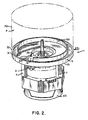
- Cover means 1 includes a plurality of legs 7 (two of which are shown in Figure 2) which rests against a portion of stator core 50.
- longitudinal stator bolt openings 9 are formed about the perimeter of the stator core 50 and the legs 7 have threaded bores 11 which register with the stator bolt openings 9 when means 1 is installed over the second end of the motor M.
- Bolts 55 are inserted through opening 9 and threaded into legs 11 to secure cover means 1 to the motor.
- the endshields ES and 3 may be attached to the stator assembly RA by epoxy or other adhesives, for example.
- Base section 5 has a central opening 15 through which shaft RS extends.
- the base section 5 further has a bearing receptacle 17 extending toward the stator assembly RA of motor M on the side 21 of the endshield 3.
- Receptacle 17, in the embodiment illustrated, is generally cylindrical in shape, with the centerline of the receptacle corresponding to the centerline of opening 15.
- a smaller diameter shoulder 19 is formed adjacent opening 15, shoulder 19 forming a step.
- Means 1 includes a bearing assembly 30 for rotatably supporting shaft RS on the enshield side 3 of the motor M.
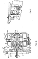
- the bearing assembly 30 includes a bearing 23, the leftward end of which, referred to in Figure 3, rests against shoulder 19.
- a pair of washers 25 are insertable on shaft RS to hold bearing 23 in place.
- bearing 23 is a conventional roller bearing for positioning the shaft RS for rotation.
- Means 1 includes mounting means 27 for attaching the cover means 1 to the pump P.
- the shaft RS also is provided with a flat 60 for attaching the shaft RS to the pump P.
- a water seal 30 is mounted to the shaft RS, the seal 30 includes an outwardly projecting collar 29 formed about opening 15. Collar 29 is formed on the opposite side of opening 15 from shoulder 17 and the collar extends around the circumference of the opening.
- An important feature of the present invention is the inclusion in cover means 1 of a migrating water drain 40 is the side 21 of the cover means 1.
- the drain 40 is a communication path formed in the side 21 of the cover means with communication with the area about the seal 30.
- a wall 47 may be provided, as shown in Figure 3, as an aid in supporting a rotating face seal (not shown) commonly use in pump designs.
- means 1 further includes an outer section 31 having an outer circumferential rim 33 defining a mating surface with pump housing PH, best seen in Figure 2. Further, section 31 has a central cavity 35 defining a drain 37 for liquid discharged through pump P. An upstanding wall 39 is formed inwardly of rim 33, the wall extending substantially around the circumference of section 31. Wall 39 and rim 33 define a channel 41 communicating with a drain D which is formed on the side 21 of the endshield 3.
- one endshield of the motor M also is an integral part of the pump P in which the motor M finds application.
- Use of the self-aligning bearing on the endshield ES side of the rotor assures proper alignment of the shaft RS in applicational use. This also occurs because endshield 3 is a part of the pump P, and the dual function cover means 1 can be mounted easily and quickly in its intended application.
Landscapes
- Engineering & Computer Science (AREA)
- Mechanical Engineering (AREA)
- General Engineering & Computer Science (AREA)
- Power Engineering (AREA)
- Motor Or Generator Frames (AREA)
- Connection Of Motors, Electrical Generators, Mechanical Devices, And The Like (AREA)
- Structures Of Non-Positive Displacement Pumps (AREA)
- Compressor (AREA)
- Details And Applications Of Rotary Liquid Pumps (AREA)
Applications Claiming Priority (2)
| Application Number | Priority Date | Filing Date | Title |
|---|---|---|---|
| US07/255,756 US4992690A (en) | 1988-10-07 | 1988-10-07 | Combination motor endshield and pump housing |
| US255756 | 1988-10-07 |
Publications (3)
| Publication Number | Publication Date |
|---|---|
| EP0363305A2 true EP0363305A2 (fr) | 1990-04-11 |
| EP0363305A3 EP0363305A3 (en) | 1990-10-10 |
| EP0363305B1 EP0363305B1 (fr) | 1993-12-01 |
Family
ID=22969718
Family Applications (1)
| Application Number | Title | Priority Date | Filing Date |
|---|---|---|---|
| EP89630185A Expired - Lifetime EP0363305B1 (fr) | 1988-10-07 | 1989-10-05 | Combinaison d'une flasque de moteur et un corps de pompe |
Country Status (9)
| Country | Link |
|---|---|
| US (1) | US4992690A (fr) |
| EP (1) | EP0363305B1 (fr) |
| JP (1) | JP2829643B2 (fr) |
| KR (1) | KR0177504B1 (fr) |
| BR (1) | BR8905090A (fr) |
| CA (1) | CA2000346C (fr) |
| DE (1) | DE68911102T2 (fr) |
| ES (1) | ES2047147T3 (fr) |
| MX (1) | MX170258B (fr) |
Cited By (2)
| Publication number | Priority date | Publication date | Assignee | Title |
|---|---|---|---|---|
| EP1146625A3 (fr) * | 2000-04-10 | 2004-04-28 | Kabushiki Kaisha MORIC | Machine électrique tournante |
| WO2013174400A1 (fr) * | 2012-05-23 | 2013-11-28 | Baumüller Nürnberg GmbH | Machine électrique |
Families Citing this family (19)
| Publication number | Priority date | Publication date | Assignee | Title |
|---|---|---|---|---|
| US5296769A (en) * | 1992-01-24 | 1994-03-22 | Electrolux Corporation | Air guide assembly for an electric motor and methods of making |
| US5475275A (en) * | 1994-02-10 | 1995-12-12 | Emerson Electric Co. | Motor assemblies with improved endshields |
| US5610461A (en) * | 1994-02-14 | 1997-03-11 | Emerson Electric Co. | Motor endshields |
| CA2191967C (fr) * | 1994-06-17 | 2000-03-21 | Josef Schneider | Appareil de nettoyage sous haute pression a isolation de securite |
| US5951241A (en) * | 1997-10-23 | 1999-09-14 | Freudenberg-Nok General Partnership | Regenerative turbine pump cover |
| US6376949B1 (en) | 2000-09-21 | 2002-04-23 | Richard R. Hayslett | Electric motor fluid drainage interface |
| DE10062364A1 (de) * | 2000-12-14 | 2002-06-20 | Bsh Bosch Siemens Hausgeraete | Antriebsvorrichtung für ein Haushaltsgerät und Verfahren zur Montage eines Elektromotors |
| CN2916195Y (zh) | 2006-01-26 | 2007-06-27 | 江门市汉宇电器有限公司 | 一种离心式排水泵 |
| US7960881B2 (en) * | 2008-10-15 | 2011-06-14 | Nidec Motor Corporation | Electric motor having drainage means |
| CN101728890A (zh) * | 2008-10-23 | 2010-06-09 | 鸿富锦精密工业(深圳)有限公司 | 马达壳体 |
| DE102008057900A1 (de) * | 2008-11-18 | 2010-05-20 | Krones Ag | Elektromotor für Flaschenverschließer |
| US8585378B2 (en) * | 2009-06-25 | 2013-11-19 | Nidec Motor Corporation | Integrated endshield and pump volute for an electric pump and method of forming an electric pump |
| US9046107B2 (en) | 2011-08-11 | 2015-06-02 | Itt Manufacturing Enterprises Llc. | Vertical double suction pump enclosing tube seal |
| US9371841B2 (en) | 2012-03-05 | 2016-06-21 | Electrolux Home Products, Inc. | Safety arrangement for an integrated heater, pump, and motor for an appliance |
| US10302082B2 (en) * | 2015-11-12 | 2019-05-28 | Nidec Motor Corporation | Pump motor for high temperature fluids |
| EP3540329B1 (fr) * | 2016-06-20 | 2021-04-28 | Bleckmann GmbH & Co. KG | Composant de système de chauffage fournissant une conception de capteur de température compact |
| PL3620097T3 (pl) * | 2018-09-07 | 2021-12-27 | Bleckmann Gmbh & Co. Kg | Układ grzewczy do ogrzewania płynnego czynnika |
| CN109707633B (zh) * | 2019-01-30 | 2023-10-03 | 深圳市研派科技有限公司 | 一种水泵 |
| CN117155049B (zh) * | 2023-10-31 | 2024-01-05 | 南昌三瑞智能科技股份有限公司 | 一种电机钢圈辅助装配装置 |
Family Cites Families (11)
| Publication number | Priority date | Publication date | Assignee | Title |
|---|---|---|---|---|
| DE1872272U (de) * | 1963-03-09 | 1963-05-16 | Heinrich Jung Fa | Tauchpumpe mit unterwassermotor. |
| US3301188A (en) * | 1964-06-18 | 1967-01-31 | Sta Rite Products Inc | Pump |
| US3364860A (en) * | 1966-09-01 | 1968-01-23 | Gorman Rupp Ind Inc | Combined recirculating and drain pump construction |
| US3425355A (en) * | 1967-07-14 | 1969-02-04 | Gen Motors Corp | Dishwasher pump assembly |
| US3576380A (en) * | 1969-08-11 | 1971-04-27 | Mccord Corp | Motor and pump assembly |
| US3664760A (en) * | 1970-09-02 | 1972-05-23 | Coleco Ind Inc | Centrifugal pump |
| US3871796A (en) * | 1973-11-15 | 1975-03-18 | Mccord Corp | Pump assembly |
| US4287662A (en) * | 1978-03-24 | 1981-09-08 | General Electric Company | Method of assembling |
| JPS56152548U (fr) * | 1980-04-16 | 1981-11-14 | ||
| JPS6038058U (ja) * | 1983-08-19 | 1985-03-16 | 株式会社神戸製鋼所 | 密閉型電動スクリュ圧縮機 |
| FR2563060B1 (fr) * | 1984-04-13 | 1988-03-18 | Guinard Pompes | Carcasse de moteur pour pompe submersible |
-
1988
- 1988-10-07 US US07/255,756 patent/US4992690A/en not_active Expired - Lifetime
-
1989
- 1989-10-05 EP EP89630185A patent/EP0363305B1/fr not_active Expired - Lifetime
- 1989-10-05 DE DE89630185T patent/DE68911102T2/de not_active Expired - Fee Related
- 1989-10-05 ES ES89630185T patent/ES2047147T3/es not_active Expired - Lifetime
- 1989-10-06 BR BR898905090A patent/BR8905090A/pt not_active IP Right Cessation
- 1989-10-06 MX MX017889A patent/MX170258B/es unknown
- 1989-10-06 JP JP1261883A patent/JP2829643B2/ja not_active Expired - Lifetime
- 1989-10-07 KR KR1019890014492A patent/KR0177504B1/ko not_active Expired - Fee Related
- 1989-10-10 CA CA002000346A patent/CA2000346C/fr not_active Expired - Fee Related
Cited By (2)
| Publication number | Priority date | Publication date | Assignee | Title |
|---|---|---|---|---|
| EP1146625A3 (fr) * | 2000-04-10 | 2004-04-28 | Kabushiki Kaisha MORIC | Machine électrique tournante |
| WO2013174400A1 (fr) * | 2012-05-23 | 2013-11-28 | Baumüller Nürnberg GmbH | Machine électrique |
Also Published As
| Publication number | Publication date |
|---|---|
| CA2000346A1 (fr) | 1990-04-07 |
| BR8905090A (pt) | 1990-05-15 |
| KR0177504B1 (ko) | 1999-05-15 |
| JP2829643B2 (ja) | 1998-11-25 |
| DE68911102T2 (de) | 1994-04-21 |
| ES2047147T3 (es) | 1994-02-16 |
| MX170258B (es) | 1993-08-12 |
| DE68911102D1 (de) | 1994-01-13 |
| EP0363305A3 (en) | 1990-10-10 |
| US4992690A (en) | 1991-02-12 |
| EP0363305B1 (fr) | 1993-12-01 |
| CA2000346C (fr) | 1993-07-06 |
| JPH02188141A (ja) | 1990-07-24 |
| KR900006690A (ko) | 1990-05-08 |
Similar Documents
| Publication | Publication Date | Title |
|---|---|---|
| US4992690A (en) | Combination motor endshield and pump housing | |
| EP1437819B1 (fr) | Moteur à aimants permanents pour pompe de circulation de systèmes de chauffage et de climatisation | |
| CN110873061B (zh) | 泵体及用于泵体的转子组件的制造方法 | |
| US4682065A (en) | Molded plastic motor housing with integral stator mounting and shaft journalling projection | |
| US7262532B2 (en) | Arrangement with an electronically commutated external rotor motor | |
| US5128571A (en) | Hard disk driving motor | |
| US10995759B2 (en) | Water pump | |
| US5079464A (en) | Multiply compartmented dynamoelectric machine | |
| CN111725934A (zh) | 流体泵 | |
| US5801467A (en) | Electric motor for a drive mechanism in particular, a pump | |
| US6252321B1 (en) | Endshield assembly with alignable bearing for an electric motor | |
| RU2300592C2 (ru) | Стиральная машина | |
| WO2019116717A1 (fr) | Moteur pour pompe de vidange, procédé de fabrication de celui-ci, et pompe de vidange comportant ledit moteur | |
| EP0607429B1 (fr) | Moteur a induction du type a induit externe | |
| EP1303025B1 (fr) | Structure de support pour un moteur électrique submersible | |
| KR100295448B1 (ko) | 모터의하우징 | |
| KR100789514B1 (ko) | 무정류자 전동기 | |
| KR19990015374U (ko) | 모터용 베어링커버의 고정구조 | |
| KR200161192Y1 (ko) | 쉐이딩 폴 모터용 엔드 플레이 조절 와셔 | |
| KR100524101B1 (ko) | 직류 무브러시 모터의 기동 간편 구조 | |
| KR200162042Y1 (ko) | 브러시리스 모터 | |
| KR970000919Y1 (ko) | 보일러용순환펌프의 마그네틱고정판 | |
| KR20050066538A (ko) | 세탁기의 모터 장착 구조 | |
| KR19990020094U (ko) | 브러시리스 dc 모터 | |
| JPH0583388U (ja) | マグネットポンプ |
Legal Events
| Date | Code | Title | Description |
|---|---|---|---|
| PUAI | Public reference made under article 153(3) epc to a published international application that has entered the european phase |
Free format text: ORIGINAL CODE: 0009012 |
|
| AK | Designated contracting states |
Kind code of ref document: A2 Designated state(s): DE ES FR GB IT SE |
|
| PUAL | Search report despatched |
Free format text: ORIGINAL CODE: 0009013 |
|
| AK | Designated contracting states |
Kind code of ref document: A3 Designated state(s): DE ES FR GB IT SE |
|
| 17P | Request for examination filed |
Effective date: 19901119 |
|
| 17Q | First examination report despatched |
Effective date: 19920526 |
|
| GRAA | (expected) grant |
Free format text: ORIGINAL CODE: 0009210 |
|
| AK | Designated contracting states |
Kind code of ref document: B1 Designated state(s): DE ES FR GB IT SE |
|
| ET | Fr: translation filed | ||
| REF | Corresponds to: |
Ref document number: 68911102 Country of ref document: DE Date of ref document: 19940113 |
|
| REG | Reference to a national code |
Ref country code: ES Ref legal event code: FG2A Ref document number: 2047147 Country of ref document: ES Kind code of ref document: T3 |
|
| ITF | It: translation for a ep patent filed | ||
| PLBE | No opposition filed within time limit |
Free format text: ORIGINAL CODE: 0009261 |
|
| STAA | Information on the status of an ep patent application or granted ep patent |
Free format text: STATUS: NO OPPOSITION FILED WITHIN TIME LIMIT |
|
| 26N | No opposition filed | ||
| EAL | Se: european patent in force in sweden |
Ref document number: 89630185.0 |
|
| PGFP | Annual fee paid to national office [announced via postgrant information from national office to epo] |
Ref country code: FR Payment date: 20010910 Year of fee payment: 13 |
|
| PGFP | Annual fee paid to national office [announced via postgrant information from national office to epo] |
Ref country code: GB Payment date: 20010914 Year of fee payment: 13 |
|
| PGFP | Annual fee paid to national office [announced via postgrant information from national office to epo] |
Ref country code: SE Payment date: 20010920 Year of fee payment: 13 |
|
| PGFP | Annual fee paid to national office [announced via postgrant information from national office to epo] |
Ref country code: DE Payment date: 20010924 Year of fee payment: 13 |
|
| PGFP | Annual fee paid to national office [announced via postgrant information from national office to epo] |
Ref country code: ES Payment date: 20011009 Year of fee payment: 13 |
|
| REG | Reference to a national code |
Ref country code: GB Ref legal event code: IF02 |
|
| PG25 | Lapsed in a contracting state [announced via postgrant information from national office to epo] |
Ref country code: GB Free format text: LAPSE BECAUSE OF NON-PAYMENT OF DUE FEES Effective date: 20021005 |
|
| PG25 | Lapsed in a contracting state [announced via postgrant information from national office to epo] |
Ref country code: SE Free format text: LAPSE BECAUSE OF NON-PAYMENT OF DUE FEES Effective date: 20021006 Ref country code: ES Free format text: LAPSE BECAUSE OF NON-PAYMENT OF DUE FEES Effective date: 20021006 |
|
| PG25 | Lapsed in a contracting state [announced via postgrant information from national office to epo] |
Ref country code: DE Free format text: LAPSE BECAUSE OF NON-PAYMENT OF DUE FEES Effective date: 20030501 |
|
| GBPC | Gb: european patent ceased through non-payment of renewal fee |
Effective date: 20021005 |
|
| EUG | Se: european patent has lapsed | ||
| PG25 | Lapsed in a contracting state [announced via postgrant information from national office to epo] |
Ref country code: FR Free format text: LAPSE BECAUSE OF NON-PAYMENT OF DUE FEES Effective date: 20030630 |
|
| REG | Reference to a national code |
Ref country code: FR Ref legal event code: ST |
|
| REG | Reference to a national code |
Ref country code: ES Ref legal event code: FD2A Effective date: 20031112 |
|
| PG25 | Lapsed in a contracting state [announced via postgrant information from national office to epo] |
Ref country code: IT Free format text: LAPSE BECAUSE OF NON-PAYMENT OF DUE FEES;WARNING: LAPSES OF ITALIAN PATENTS WITH EFFECTIVE DATE BEFORE 2007 MAY HAVE OCCURRED AT ANY TIME BEFORE 2007. THE CORRECT EFFECTIVE DATE MAY BE DIFFERENT FROM THE ONE RECORDED. Effective date: 20051005 |