EP0363418B1 - Verfahren und vorrichtung zur adaptiven blocktransformationscodierung von bildern - Google Patents
Verfahren und vorrichtung zur adaptiven blocktransformationscodierung von bildern Download PDFInfo
- Publication number
- EP0363418B1 EP0363418B1 EP88905274A EP88905274A EP0363418B1 EP 0363418 B1 EP0363418 B1 EP 0363418B1 EP 88905274 A EP88905274 A EP 88905274A EP 88905274 A EP88905274 A EP 88905274A EP 0363418 B1 EP0363418 B1 EP 0363418B1
- Authority
- EP
- European Patent Office
- Prior art keywords
- coefficients
- block
- image
- quantizing
- quantization
- Prior art date
- Legal status (The legal status is an assumption and is not a legal conclusion. Google has not performed a legal analysis and makes no representation as to the accuracy of the status listed.)
- Expired - Lifetime
Links
Images






Classifications
-
- H—ELECTRICITY
- H04—ELECTRIC COMMUNICATION TECHNIQUE
- H04N—PICTORIAL COMMUNICATION, e.g. TELEVISION
- H04N19/00—Methods or arrangements for coding, decoding, compressing or decompressing digital video signals
- H04N19/10—Methods or arrangements for coding, decoding, compressing or decompressing digital video signals using adaptive coding
- H04N19/102—Methods or arrangements for coding, decoding, compressing or decompressing digital video signals using adaptive coding characterised by the element, parameter or selection affected or controlled by the adaptive coding
- H04N19/124—Quantisation
- H04N19/126—Details of normalisation or weighting functions, e.g. normalisation matrices or variable uniform quantisers
-
- H—ELECTRICITY
- H04—ELECTRIC COMMUNICATION TECHNIQUE
- H04N—PICTORIAL COMMUNICATION, e.g. TELEVISION
- H04N19/00—Methods or arrangements for coding, decoding, compressing or decompressing digital video signals
- H04N19/60—Methods or arrangements for coding, decoding, compressing or decompressing digital video signals using transform coding
-
- H—ELECTRICITY
- H04—ELECTRIC COMMUNICATION TECHNIQUE
- H04N—PICTORIAL COMMUNICATION, e.g. TELEVISION
- H04N19/00—Methods or arrangements for coding, decoding, compressing or decompressing digital video signals
- H04N19/10—Methods or arrangements for coding, decoding, compressing or decompressing digital video signals using adaptive coding
- H04N19/102—Methods or arrangements for coding, decoding, compressing or decompressing digital video signals using adaptive coding characterised by the element, parameter or selection affected or controlled by the adaptive coding
- H04N19/124—Quantisation
Definitions
- the present invention relates to block transform digital image compression and transmission methods and apparatus, and more particularly to such methods and apparatus exploiting characteristics of the human visual system for increased image compression.
- block transform coding of digital images for bandwidth compression prior to transmission over a limited bandwidth communication channel.
- the digital image is formatted into blocks (e.g. 16 x 16 pixels) and a spatial frequency transformation such as a discrete cosine transform (DCT) is applied to each block to generate 16 x 16 blocks of transform coefficients.
- DCT discrete cosine transform
- Each block of transform coefficients is ordered into a one-dimensional vector such that the frequencies represented by the coefficients generally increase along the vector.
- the transform coefficients are quantized and coded using a minimum redundancy coding scheme such as Huffman coding, and run length coding for runs of coefficients having zero magnitude.
- the coded transform coefficients are transmitted over the limited bandwidth channel.
- the image signal is decoded using operations that are the inverse of those employed to encode the digital image.
- This technique is capable of producing advantageously high image compression ratios, thereby enabling low bit rate transmission of digital images over limited bandwidth communication channels.
- Block adaptive transform coding schemes have been proposed wherein transform blocks are sorted into classes by the level of image activity present in the blocks. Within each activity level, coding bits are allocated to individual transform coefficients with more bits being assigned to "busy" areas of the image and fewer bits assigned to "quiet” areas. (See “Adaptive Coding of Monochrome and Color Images” by W. H. Chen and C. H. Smith, IEEE Transactions on Communications, Vol. COM-25, No. 11, November 1977, pg 1285-1292). Although such block adaptive coding schemes achieve low overall bit rates, with low image distortion (in the sense of mean square error between the pixel values of the original image and the transmitted image), even lower bit rates may be achieved by taking into account the fact that transmission errors (e.g.
- the objects of the present invention are achieved in a block transform image compression technique by accounting in the quantization step for the fact that the human visual system is less sensitive to noise in the presence of image detail. Accordingly, in a method or apparatus for coding and transmitting a digital image over a limited bandwidth communication channel, in a transmitter or transceiver, a two dimensional spatial frequency block transformation is performed on a digital image to produce blocks of transform coefficients.
- the transform coefficients are adaptively quantized by measuring the amount of image detail within a block and quantizing the coefficients in accordance with a model of the visibility of quantization noise in the presence of the measured image detail.
- the quantized transform coefficients are encoded and transmitted.
- the transform coefficients are quantized by arranging the coefficients from a block into a one dimensional vector in order of increasing spatial frequency.
- the coefficients in the vector are sequentially quantized starting with the coefficient representing the lowest frequency, by forming an estimate of the contrast of the image structure in the block from the previous coefficients in the vector, and determining the quantization for the current coefficient as the function of the contrast estimate.
- the function relates the contrast estimate to the visibility of quantization error in the presence of image detail having such contrast.
- image detail characterized by an edge separating uniform areas in a block is detected, and the quantization based upon contrast is disabled when such an edge is detected, thereby improving the performance of the technique.
- the adaptive quantization is implemented by adaptive normalization followed by fixed quantization.
- the bit rate is reduced by effectively increasing the quantization intervals for the DCT coefficients until the quantization noise is just below the threshold of visibility.
- the actual quantization step remains constant for all coefficients but is effectively varied by a preceding normalization step which divides the coefficients by some number, referred to as the normalization factor.
- the result of the normalization step is then quantized, typically by rounding to the nearest integer. A higher normalization factor will result in a lower input range to the fixed quantizer, which in turn results in fewer output quantization levels.
- the inverse normalization step is merely a multiplication by the same normalization value employed at the transmitter. Compression results from the subsequent use of Huffman coding for amplitudes of the coefficients which have reduced values due to the normalization process, and run-length coding for the coefficients which are quantized to zero.
- Errors from the quantization process arise when the DCT coefficients are rounded to either the nearest higher quantization level or the nearest lower quantization level.
- the values of the DCT coefficients basically represent the amplitudes of spatial frequency components of an image block, wherein the absolute value is proportional to image contrast, while the sign of the coefficient determines the phase.
- the rounding process in the quantization step results in the possibility that a spatial frequency component may have an incorrect contrast.
- the quantization process employed in the following description will be rounding to the nearest quantization level, although other types of rounding, such as truncation (or rounding down), may be employed.
- Nearest level rounding can produce several results. If the nearest level happens to be lower than the coefficients original value, the spatial frequency component represented by the coefficient will have a reduced contrast. If the quantized value is higher than the original value, the spatial frequency component will appear with a higher contrast. With nearest level rounding type quantization, the maximum error is bounded by half the quantization interval. If the error is large enough, the spatial frequency component becomes clearly visible, appearing to be superimposed over the original image block. When many coefficient values are incorrect, the appearance of the errors approaches that of white noise.
- the quantization errors in the DCT coefficient values result in spatial frequency components having either too high or too low a contrast, with the maximum contrast error bounded by one half the width of the quantization interval.
- the most straightforward way of applying human visual data to the quantization process is to use the spatial frequency contrast sensitivity function (CSF) as described in the Nill article noted above.
- the CSF is derived by taking the inverse of the visual contrast threshold, which describes the contrast at which a particular spatial frequency becomes detectable. Using the CSF the effective quantization interval is allowed to be as large as possible without resulting in the visibility of quantization error.
- the normalization value for a DCT coefficient is made proportional to the inverse of the contrast sensitivity for the spatial frequency represented by the DCT coefficient. It is advantageous to perform these calculations in a nonlinear visual space for amplitude of the code values of the image. Psycho-physical research indicates that this space is very close to a one third power function of display intensity for average viewing conditions.
- the visual weighting of the coefficients as described above is valid for situations which are consistent with the experiments employed to measure the CSF, which also happens to be the most critical viewing conditions: i.e. when the spatial frequency component error appears in an otherwise uniform field.
- the human visual contrast sensitivity to different spatial frequencies in the presence of image structure is much less than that in the presence of a uniform field.
- This property is referred to as visual masking and is utilized in the present invention to improve the image quality or reduce the bit rate in a block transform image compression technique. Since the spatial frequency contrast errors are occurring in the presence of the original image, their visibility is masked by the inherent image structure. Thus, the quantization errors can be allowed to be larger than that ascertained merely from the CSF, and if performed correctly no new visible errors will be introduced, yet the bit rate can be reduced due to the larger quantization intervals.
- Fig. 3 is a graph of psycho-physical experimental data showing the affect on the threshold visibility of a single spatial frequency in the presence of white noise, plotted on a log-log scale.
- the ordinate of Fig. 3 is the log threshold contrast for visibility of the spatial frequency
- the abscissa of Fig. 3 is the log RMS (root mean square) contrast of the noise.
- the threshold contrast T a for visibility of a spatial frequency is not substantially affected until the noise contrast reaches a critical value N erit , above which the effect of noise on the visibility threshold is essentially a straight line having a slope of one in log-log space.
- a block diagram of a system for compressing and transmitting a digital image according to the present invention is shown in Fig. 1.
- a transmitter 10 acquires a digital image from a source (not shown) such as an image sensor, film scanner or a digital image recorder.
- the digital image comprises for example 512 x 512 8-bit pixels.
- the transmitter 10 compresses and encodes the digital image, and supplies the encoded digital image signal to a limited bandwidth communication channel 12 such as a standard 3.3 khz bandwidth telephone line.
- the encoded digital image signal is received from the channel 12 by a receiver 14 that decodes the compressed digital image signal and reconstructs the digital image.
- the transmitter 10 receives the digital image I and formats (16) the image into blocks l(x,y).
- the currently preferred block size is 16 x 16 pixels.
- a two-dimensional discrete cosine transform is performed (18) on each block to generate the corresponding block T(i,j) of transform (2 - D DCT) coefficients. Since the 2 - D DCT is a well known procedure, (see above referred U.S. Patent No. 4,302,775) no further description will be given herein of the (2 - D DCT) operation.
- the transform coefficients T(i,j) for each block are ordered (20) into a one-dimensional array T(k) in order of increasing spatial frequency, for example by employing a zig-zag scan along diagonals of the block of coefficients.
- the coefficients are adaptively quantized (22) in accordance with the visibility of quantization noise in the presence of image detail within a block.
- the adaptive quantization (22) is accomplished by variable normalization (24) prior to a fixed quantization (26).
- a variable quantization could be employed.
- the transform coefficients T(k) are normalized by dividing each transform coefficient by a normalization factor N(k) as follows: where TN(k) is the normalized transform coefficient value.
- the normalization factor N(k) is determined (28) as described below based on the visibility of quantization noise in the presence of image detail in the block.
- the normalized coefficients TN(k) are quantized (26) to form quantized coefficients TN(k).
- the quantized coefficients are encoded (30) using a minimum redundancy coding scheme to produce code values CV(k).
- a presently preferred coding scheme is a Huffman code with run-length coding for strings of zero magnitude coefficients. Since Huffman and run-length coding are well known in the art, (see above reference U.S. Patent No. 4,302,775) no further description of the coding process will be given herein.
- the coded coefficients are transmitted over the channel 12 to receiver 14.
- the receiver 14 performs the inverse of the operations performed by the transmitter 10 to recover the digital image.
- the code values CV(k) are decoded (32) to produce normalized coefficients TN(k).
- the normalized coefficients TN(k) are denormalized (34) employing denormalization values N- 1 (k) that are the inverse of the normalization array N(k) employed in the transmitter to produce the denormalized coefficients T(k).
- the transform coefficients are denormalized by multiplying by the normalization coefficients N(k).
- the denormalization values N -1 (k) are recovered (36) at the receiver from the coefficient values as described in more detail below.
- the one-dimensional string of reconstructed coefficient values T(k) are re-formated (38) into two-dimensional blocks T(i,j) and the blocks of coefficients are inversely transformed (40) into image values Î(x,y). Finally, the blocks of image values are re-formatted (42) into the digital image
- the transform coefficients T(k) to be normalized are arranged in increasing order of spatial frequency, in a sequential processing scheme, information about the values of all the previous coefficients which represent lower spatial frequencies, is available when processing any given coefficient in the one dimensional array.
- the image detail represented by the previous coefficients is the low pass image detail.
- the quantization noise in coefficient T(k) represents the signal
- the previous coefficients T(0)-T(k-1) represent the low pass noise (image detail) masking the visibility of the quantization noise.
- the RMS contrast of the low pass image detail Crms is represented by:
- the amplitude of this rms contrast will determine the visibility threshold of the quantization error for quantized coefficient TN(k).
- the 16 x 16 pixel subimage blocks will subtend a 0.5 by 0.5 degree visual field. It is believed, as the result of experiment, that the masking effect does not extend uniformly over such a wide visual field. In fact, at as little as 0.4 degrees away from the site of image detail, the masking effect may be less than half the amount at the detail site. This impacts the determination of the normalization factors in that, when the detail in a subimage is not homogeneous, the masking factor determined from the previous coefficients may not be appropriate. An example would be a subimage block containing two uniform areas widely of differing grey level.
- adaptive normalization is not practiced on the first m(e.g. 10) coefficients in the block.
- the normalization factor for these coefficients is set to a predetermined value (e.g. 1) and the summation process is started at the m + 1 st coefficient.
- the detail estimate C , ms is started with the m th coefficient value, such that:
- the first m coefficients are denormalized with the predetermined constant, and the detail estimate C , ms is begun at the m th coefficient value.
- an edge produces energy in the transform coefficients in approximate proportion to the inverse of the spatial frequency represented by the coefficient
- the high frequency coefficients may still contribute sufficient value to the detail estimate C , ms to produce an incorrectly calculated masking effect.
- this situation is accounted for by employing an edge detector prior to determining the normalization factor, and disabling the adaptive normalization when an edge is detected.
- a simple edge detector is implemented by summing the absolute values of the first m coefficients and comparing the sum to a predetermined value C 1 to determine whether an edge is present.
- the adaptive normalization is disabled for the block by setting all of the normalization factors equal to one.
- a more sophisticated edge detector may be implemented at the cost of increased computation complexity by calculating the ratio of the variance of the low frequencies in the image block to the variance of all the frequencies in the block.
- a high ratio will indicate the presence of a high contrast edge.
- the calculation of the variance ratio may occur in parallel with the calculation of the DCT, and the results employed when determining the normalization factors.
- the normalization factors for the first m coefficients are set equal to one (44).
- An edge detect value D e is computed (according to the simple method described above) by summing the absolute values of the first m coefficients (46). The value of D e is compared to the predetermined threshold C 1 (48). If the edge detect value is greater than the threshold C1, an edge has been detected, and further adaptive normalization is disabled by setting the remainder of the normalization factors equal to one (50).
- edge detect value is less than or equal to the predetermined constant C
- subsequent coefficients are denormalized (52). This is done to enable the normalization factors to be recovered at the receiver without error.
- Using the denormalized quantized coefficients at the transmitter to determine the normalization factors insures that the values later employed at the receiver will be identical.
- the coefficients are processed sequentially, and the coefficient TN(k-1) to be denormalized is held over from the previous processing cycle by delay (54).
- a detail estimated c rms is computed (56) according to equation (3) above.
- the detail estimate c, m is employed (58) to address a look up table (60) that contains the normalization factor values N(k).
- the normalization factor N(k) is employed to normalize the coefficient T(k) prior to quantization and will be employed in the next cycle to denormalize the quantized coefficient TN(k).
- Denormalization factors stored in look up table (60) are generated empirically from the relationship shown in Fig. 3.
- the square root of the sum of the squares of the coefficient values is the preferred estimate of image detail for selecting the normalization factors, the square and square root operations are computationally intensive. To provide a more computationally efficient process that can be accomplished in less time by less sophisticated hardware (e.g. a microprocessor) with only a slight reduction in compression efficiency, the sum of the absolute values of the denormalized quantized coefficients may be employed as the detail estimate C , ms . This alternative method of forming the detail estimate is shown in dashed box (56') in Fig. 2.
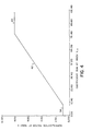
- Fig. 4 shows a plot of the actual values used as normalization factors N(k) for coefficients T(k) versus the sum of the absolute values of the coefficients from m to k-1, where m is 10.
- the lower flat portion 58 of the curve in Fig. 4 reflects the threshold portion of the curve in Fig. 3.
- the upper flat portion 60 of the curve in Fig. 4 is imposed by the limited number of bits (e.g. 10) used in the code word to define the normalization factor N(k).
- the slope of one in the sloping portion (62) of the curve matches the slope of the curve in Fig. 3.
- the required dynamic range of the sloping portion 62 of the curve in Fig. 4 was determined empirically by observing the effects of compression and decompression on an assortment of digitized photographic images. A dynamic range was chosen consistent with the number of bits in the code word to produce maximum image compression without introducing visible quantization noise in the processed image.
- An edge detect value D e is computed (64) by summing the absolute values of the first m coefficients.
- the edge detect value is compared with the predetermined threshold C 1 (66) to determine if an edge is present in the subportion of the image. If an edge is detected, all of the denormalization factors are set equal to one (68). If an edge is not detected, denormalization factors are determined for subsequent coefficients by forming a detail estimate (72) C , ms for each coefficient.
- the detail estimate is the square root of the sum of the squares of previous denormalized coefficient values from the m th coefficient value to the immediately previous value (k-1 st ). A running sum is accumulated in the previous denormalized value is supplied via a one cycle delay (74).
- the detail estimate is employed to address (76) a look up table (78) that contains the denormalization factors, which are the reciprocals of the normalization factors employed in the transmitter 10.
- the values stored in look up table (78) may be identical to values stored in the look up table (60) in the transmitter, and the denormalization may be implemented by multiplying by the normalization factors.
- the block adaptive transform coding scheme according to the present invention can also be combined with a global visual weighting quantization scheme to produce even further improvements in compression ratio.
- a global visually weighted quantization scheme a global normalization array representing the relative human visual response to each of the spatial frequencies represented by the corresponding DCT coefficients is applied to all the blocks of the image.
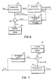
- Fig. 6 illustrates the manner in which the human visual weighting technique is combined with the adaptive normalization technique in the transmitter.
- a global normalization array 80 contains normalization factors representing the relative human visual response to the spatial frequencies represented by the DCT coefficients.
- the local normalization factors based upon the image detail in the block are determined (28) as described above.
- the global normalization factor G(k) for the kLh coefficient is multiplied (82) by the local normalization factor N(k), to produce the final normalization factor to normalize (24) the coefficient T(k).
- the only change to the details of the computation of the local normalization factor N(k) as described in Fig. 2 involves employing the final normalization factor G(k) x N(k) in the denormalization (52) of the coefficient. This slight change is indicated by dashed lines in Fig. 2.
- the recovery of the final normalization factor at the receiver is shown in Fig. 7.
- the local denormalization factor N-1 (k) is determined (36) it is multiplied (81) by a global denormalization factor G- 1- (k) from a global denormalization array (83).
- the global denormalization array values are the reciprocals of the global normalization values. No modification to the details for determining the local denormalization factors as shown in Fig. 5 are required.
- the system includes two or more transceivers 84 coupled to a telephone transmission line 86.
- Each of the transceivers 84 is connected to a video signal source such as a video camera 88, and to a video display such as a video monitor 90.
- Each transceiver 84 contains a standard video interface 92 that receives video signals from the video source, digitizes the signals, and supplies the digital image signals to a digital frame store 94.
- the video interface 92 also receives digital image signals from the digital frame store 94 and produces a standard video signal for display on the video monitor 90.
- Each transceiver is controlled by an Intel 80186 microprocessor 96 having conventional ROM 98 and RAM 100 for storing the control programs and temporary storage of data respectively.
- the microprocessor 96 performs the run-length and Huffman coding and decoding, and the block adaptive normalization and denormalization on the DCT coefficients.
- the coded DCT coefficients are sent and received over a telephone line 86 via an R96 FT/SC modem 102.
- the forward discrete cosine transforms DCT (in the transmitting mode) and reverse transforms (in the receiving mode) are performed by a TMS 32020 Digital Signal Processor 104 having a conventional RAM 105 for storing the DCT transform program.
- the microprocessor 96 retrieves one 16 x 16 block of digital image data at a time from an image buffer 106 in the digital frame store 94.
- the 16 x 16 block of digital image data is temporarily stored in a dual port SRAM 108, that is accessible by both the microprocessor 96 and the digital signal processor 104.
- the digital signal processor 104 performs the discrete cosine transform and returns the 16 x 16 block of transform coefficients to the dual port SRAM 108.
- the block of transform coefficients are then normalized and compressed (Huffman and run-length encoded) by the microprocessor 96.
- the compressed signal is stored in a compressed image buffer 110 in digital frame store 94 and transmitted at the data rate of the modem 102. This cycle is repeated on each block until the entire image has been compressed, and transmitted
- a compressed digital image is received via modem 102 and stored in compressed image buffer 110.
- One block at a time of compressed DCT coefficients is retrieved from the compressed image buffer 110 and denormalized and expanded by microprocessor 96.
- the expanded block of DCT coefficients is supplied to dual port SRAM 108.
- the digital signal processor 104 inversely transforms the coefficients to produce a 16 x 16 block of digital image values, which are temporarily stored in SRAM 108.
- Microprocessor 96 transfers the block of digital image values from the dual port SRAM 108 to image buffer 106. This cycle is repeated until the entire image has been received decompressed and stored in image buffer 106.
- the image is displayed as it is reviewed on the video monitor 90 via video interface 92.
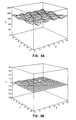
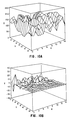
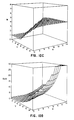
- Fig. 9 shows the results of the processing steps for compression and reconstruction of a single 16 x 16 pixel image block having low amplitude detail. Although the image blocks were processed in linear array form, they are shown here as two dimensional arrays to aid in visualization of the processing.
- Block A in Fig. 9 shows the input image values l(x,y).
- Block B shows the values of the transform coefficients T(x,y).
- Block C shows the local normalization factors N(x,y) which are all ones in this case due to the low amplitude of the image detail.
- Block D shows the final normalization factors G(x,y) x N(x,y) comprising the adaptively determined local normalization factors N(x,y) times the global human visual response normalization factors G(x,y). Because the local normalization factors are all ones, block D is simply the global normalization array.
- the global normalization array employed here takes into account the reduced response of the human visual system to diagonally oriented spatial frequencies, hence the appearance of the diagonal ridge 110 in the two-dimensional plot of the normalization values.
- Block E shows the quantized and denormalized coefficient values T(x,y) as recovered at the receiver.
- Block F shows the reconstructed image block I(x,y) at the receiver.
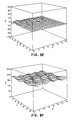
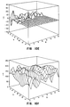
- Fig. 10 is a plot similar to Fig. 9, showing the processing steps for compression and expansion of an image block A having a high amplitude image detail. Comparing the local normalization factors of block C in Fig. 10 with the global normalization factors of block D in Fig. 9, it can be appreciated that the block adaptive normalization method of the present invention will provide significantly further compression of the image.
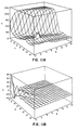
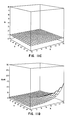
- Fig. 11 is a group of plots similar to Figs. 9 and 10 showing an image block A having a high amplitude edge. The presence of the edge resulted in high amplitude, low frequency coefficients as seen in block B. The presence of the edge was detected, and the local normalization (factors block C) were all set equal to one.
- the technique described can also be applied to a color digital image, for example by separating the image into a luminance component and chrominance component, and applying the block adaptive normalization technique to the luminance component.
- the chrominance component is of lower resolution than the luminance component, the gains to be made by applying the more sophisticated compression techniques (of which the present invention is an example) to the chrominance component do not justify the added complexity.
- the present inventors have achieved excellent results in compressing color digital images by separating the images into a luminance component and two lower resolution chrominance components, and applying the block adaptive transform technique to the luminance components, and the DCT transform without block adaptive feature to the chrominance components.
- the present invention is useful in digital image transmission systems for transmitting a digital image over a narrow-band communication channel.
- the invention produces improved compression of the digital image without introducing visible artifacts, thereby enabling improvements in image quality for the same transmission time, or faster transmission times for the same quality of image, or allowing the use of narrower bandwidth communication channels for the same transmission time and image quality.
Landscapes
- Engineering & Computer Science (AREA)
- Multimedia (AREA)
- Signal Processing (AREA)
- Compression Or Coding Systems Of Tv Signals (AREA)
Claims (14)
Applications Claiming Priority (3)
| Application Number | Priority Date | Filing Date | Title |
|---|---|---|---|
| US57404 | 1987-06-02 | ||
| US07/057,404 US4774574A (en) | 1987-06-02 | 1987-06-02 | Adaptive block transform image coding method and apparatus |
| PCT/US1988/001607 WO1988010049A1 (en) | 1987-06-02 | 1988-05-19 | Adaptive block transform image coding method and apparatus |
Publications (3)
| Publication Number | Publication Date |
|---|---|
| EP0363418A1 EP0363418A1 (de) | 1990-04-18 |
| EP0363418B1 true EP0363418B1 (de) | 1993-10-06 |
| EP0363418B2 EP0363418B2 (de) | 1996-10-23 |
Family
ID=22010391
Family Applications (1)
| Application Number | Title | Priority Date | Filing Date |
|---|---|---|---|
| EP88905274A Expired - Lifetime EP0363418B2 (de) | 1987-06-02 | 1988-05-19 | Verfahren und vorrichtung zur adaptiven blocktransformationscodierung von bildern |
Country Status (5)
| Country | Link |
|---|---|
| US (1) | US4774574A (de) |
| EP (1) | EP0363418B2 (de) |
| JP (1) | JPH02503733A (de) |
| DE (1) | DE3884802T3 (de) |
| WO (1) | WO1988010049A1 (de) |
Families Citing this family (201)
| Publication number | Priority date | Publication date | Assignee | Title |
|---|---|---|---|---|
| US6563875B2 (en) * | 1987-12-30 | 2003-05-13 | Thomson Licensing S.A. | Adaptive method of encoding and decoding a series of pictures by transformation, and devices for implementing this method |
| US5162923A (en) * | 1988-02-22 | 1992-11-10 | Canon Kabushiki Kaisha | Method and apparatus for encoding frequency components of image information |
| US4897717A (en) * | 1988-03-30 | 1990-01-30 | Starsignal, Inc. | Computer-based video compression system |
| US4951139A (en) * | 1988-03-30 | 1990-08-21 | Starsignal, Inc. | Computer-based video compression system |
| JPH0220185A (ja) * | 1988-07-08 | 1990-01-23 | Ricoh Co Ltd | 動画像伝送方式 |
| US4991009A (en) * | 1988-07-08 | 1991-02-05 | Ricoh Company, Ltd. | Dynamic image transmission system |
| US4963995A (en) * | 1988-12-27 | 1990-10-16 | Explore Technology, Inc. | Audio/video transceiver apparatus including compression means |
| US5057932A (en) * | 1988-12-27 | 1991-10-15 | Explore Technology, Inc. | Audio/video transceiver apparatus including compression means, random access storage means, and microwave transceiver means |
| US5164839A (en) * | 1988-12-27 | 1992-11-17 | Explore Technology, Inc. | Method for handling audio/video source information |
| US6124882A (en) * | 1992-02-19 | 2000-09-26 | 8×8, Inc. | Videocommunicating apparatus and method therefor |
| JPH02305182A (ja) * | 1989-05-19 | 1990-12-18 | Fuji Photo Film Co Ltd | 画像信号圧縮符号化装置 |
| US5121216A (en) * | 1989-07-19 | 1992-06-09 | Bell Communications Research | Adaptive transform coding of still images |
| US5063608A (en) * | 1989-11-03 | 1991-11-05 | Datacube Inc. | Adaptive zonal coder |
| US4974078A (en) * | 1989-11-13 | 1990-11-27 | Eastman Kodak Company | Digital compression method and system with improved coding efficiency |
| US5150433A (en) * | 1989-12-01 | 1992-09-22 | Eastman Kodak Company | Histogram/variance mechanism for detecting presence of an edge within block of image data |
| US5164980A (en) * | 1990-02-21 | 1992-11-17 | Alkanox Corporation | Video telephone system |
| US5347305A (en) * | 1990-02-21 | 1994-09-13 | Alkanox Corporation | Video telephone system |
| US5021891A (en) * | 1990-02-27 | 1991-06-04 | Qualcomm, Inc. | Adaptive block size image compression method and system |
| US5107345A (en) * | 1990-02-27 | 1992-04-21 | Qualcomm Incorporated | Adaptive block size image compression method and system |
| US5079621A (en) * | 1990-06-29 | 1992-01-07 | Eastman Kodak Company | Dct transform compression, transmission and recovery of digital color using virtual filtering mechanism |
| US5202957A (en) * | 1990-08-09 | 1993-04-13 | Future Communications | Full motion video telephone system |
| EP0472239B1 (de) * | 1990-08-22 | 1995-11-08 | Philips Patentverwaltung GmbH | Verfahren zur Ermittlung horizontaler Bewegungen in den Bildinhalten eines Fernsehsignals |
| KR930003964B1 (ko) * | 1990-08-31 | 1993-05-17 | 삼성전자 주식회사 | 화상신호의 전송 및 저장시 데이타의 감축 효율을 높이기 위한 부호화방식 |
| US5172227A (en) * | 1990-12-10 | 1992-12-15 | Eastman Kodak Company | Image compression with color interpolation for a single sensor image system |
| JPH04221465A (ja) * | 1990-12-21 | 1992-08-11 | Matsushita Electric Ind Co Ltd | 記録装置 |
| US5253275A (en) | 1991-01-07 | 1993-10-12 | H. Lee Browne | Audio and video transmission and receiving system |
| US5113256A (en) * | 1991-02-08 | 1992-05-12 | Zenith Electronics Corporation | Method of perceptually modeling a video image signal |
| US5870497A (en) * | 1991-03-15 | 1999-02-09 | C-Cube Microsystems | Decoder for compressed video signals |
| AU658432B2 (en) * | 1991-06-04 | 1995-04-13 | Qualcomm Incorporated | Adaptive block size image compression method and system |
| US5822462A (en) * | 1991-09-11 | 1998-10-13 | Canon Kabushiki Kaisha | Image processing apparatus |
| US5214507A (en) * | 1991-11-08 | 1993-05-25 | At&T Bell Laboratories | Video signal quantization for an mpeg like coding environment |
| US5159449A (en) * | 1991-12-26 | 1992-10-27 | Workstation Technologies, Inc. | Method and apparatus for data reduction in a video image data reduction system |
| US6121998A (en) * | 1992-02-19 | 2000-09-19 | 8×8, Inc. | Apparatus and method for videocommunicating having programmable architecture permitting data revisions |
| US5313298A (en) * | 1992-03-05 | 1994-05-17 | Rubin, Bednarek And Associates, Inc. | Video companding method and system |
| GB9206651D0 (en) * | 1992-03-26 | 1992-05-06 | Solid State Logic Ltd | Video processing |
| JPH0622301A (ja) * | 1992-06-30 | 1994-01-28 | Sony Corp | 画像符号化装置 |
| US5289548A (en) * | 1992-06-30 | 1994-02-22 | Loral Aerospace Corp. | Compression and reconstruction of radiological images |
| CA2094524A1 (en) * | 1992-07-30 | 1994-01-31 | Ephraim Feig | Digital image processor for color image compression |
| JP3526057B2 (ja) * | 1992-07-31 | 2004-05-10 | キヤノン株式会社 | 動画像伝送装置 |
| US5526143A (en) * | 1992-09-16 | 1996-06-11 | Scitex Corporation Ltd. | Apparatus and technique for generating a screened reproduction of an image |
| EP0607484B1 (de) * | 1993-01-20 | 1998-09-09 | Samsung Electronics Co. Ltd. | Verfahren und Vorrichtung zur Codierung und Decodierung von Bilddaten |
| WO1994018799A1 (en) * | 1993-02-03 | 1994-08-18 | Qualcomm Incorporated | Interframe video encoding and decoding system |
| US5576765A (en) * | 1994-03-17 | 1996-11-19 | International Business Machines, Corporation | Video decoder |
| US5654760A (en) * | 1994-03-30 | 1997-08-05 | Sony Corporation | Selection of quantization step size in accordance with predicted quantization noise |
| US5748786A (en) | 1994-09-21 | 1998-05-05 | Ricoh Company, Ltd. | Apparatus for compression using reversible embedded wavelets |
| GB2293734B (en) * | 1994-09-20 | 1997-04-09 | Ricoh Kk | Method for compression using reversible embedded wavelets |
| JP3302229B2 (ja) | 1994-09-20 | 2002-07-15 | 株式会社リコー | 符号化方法、符号化/復号方法及び復号方法 |
| US6195465B1 (en) | 1994-09-21 | 2001-02-27 | Ricoh Company, Ltd. | Method and apparatus for compression using reversible wavelet transforms and an embedded codestream |
| US5867602A (en) * | 1994-09-21 | 1999-02-02 | Ricoh Corporation | Reversible wavelet transform and embedded codestream manipulation |
| US6549666B1 (en) | 1994-09-21 | 2003-04-15 | Ricoh Company, Ltd | Reversible embedded wavelet system implementation |
| US6873734B1 (en) | 1994-09-21 | 2005-03-29 | Ricoh Company Ltd | Method and apparatus for compression using reversible wavelet transforms and an embedded codestream |
| US5966465A (en) * | 1994-09-21 | 1999-10-12 | Ricoh Corporation | Compression/decompression using reversible embedded wavelets |
| US5881176A (en) | 1994-09-21 | 1999-03-09 | Ricoh Corporation | Compression and decompression with wavelet style and binary style including quantization by device-dependent parser |
| US6229927B1 (en) | 1994-09-21 | 2001-05-08 | Ricoh Company, Ltd. | Reversible embedded wavelet system implementation |
| KR0159434B1 (ko) * | 1995-04-19 | 1999-01-15 | 김광호 | 휴먼 비쥬얼 시스템 모델링을 이용한 웨이블렛 영상 압축/복원장치 및 방법 |
| KR100196838B1 (ko) * | 1995-12-23 | 1999-06-15 | 전주범 | 블럭벌 상관 관계에 의한 부호화 장치 |
| US5905819A (en) * | 1996-02-05 | 1999-05-18 | Eastman Kodak Company | Method and apparatus for hiding one image or pattern within another |
| US5737451A (en) * | 1996-04-10 | 1998-04-07 | Eastman Kodak Company | Method and apparatus for suppressing blocking artifacts in block-transform coded images |
| DE69721373T2 (de) * | 1996-05-14 | 2004-04-15 | Daewoo Electronics Corp. | Quantisierer für ein Videokodierungssystem |
| US5809178A (en) * | 1996-06-11 | 1998-09-15 | Apple Computer, Inc. | Elimination of visible quantizing artifacts in a digital image utilizing a critical noise/quantizing factor |
| US6031929A (en) * | 1996-07-18 | 2000-02-29 | University Of Pittsburgh | Image facsimile with real time image segmentation |
| US5999656A (en) * | 1997-01-17 | 1999-12-07 | Ricoh Co., Ltd. | Overlapped reversible transforms for unified lossless/lossy compression |
| US6091767A (en) | 1997-02-03 | 2000-07-18 | Westerman; Larry Alan | System for improving efficiency of video encoders |
| US7212229B2 (en) * | 1997-04-04 | 2007-05-01 | Eastman Kodak Company | Digital camera providing image processing for an attachable printer |
| US7453498B2 (en) * | 1998-03-26 | 2008-11-18 | Eastman Kodak Company | Electronic image capture device and image file format providing raw and processed image data |
| JP4131052B2 (ja) | 1998-07-17 | 2008-08-13 | ソニー株式会社 | 撮像装置 |
| US6411740B1 (en) * | 1998-11-04 | 2002-06-25 | Sharp Laboratories Of America, Incorporated | Method for non-uniform quantization in a resolution hierarchy by use of a nonlinearity |
| US6356668B1 (en) | 1998-12-29 | 2002-03-12 | Eastman Kodak Company | Method for efficient rate control |
| US6671420B1 (en) | 1999-02-16 | 2003-12-30 | Sharp Laboratories Of America, Inc. | Method for processing saturated intervals in video sequences |
| US7019778B1 (en) | 1999-06-02 | 2006-03-28 | Eastman Kodak Company | Customizing a digital camera |
| US6658162B1 (en) | 1999-06-26 | 2003-12-02 | Sharp Laboratories Of America | Image coding method using visual optimization |
| US6314452B1 (en) | 1999-08-31 | 2001-11-06 | Rtimage, Ltd. | System and method for transmitting a digital image over a communication network |
| US20070132860A1 (en) * | 2000-04-14 | 2007-06-14 | Prabhu Girish V | Method for customizing a digital camera using queries to determine the user's experience level |
| US7024046B2 (en) | 2000-04-18 | 2006-04-04 | Real Time Image Ltd. | System and method for the lossless progressive streaming of images over a communication network |
| US7304677B2 (en) * | 2000-12-13 | 2007-12-04 | Eastman Kodak Company | Customizing a digital camera based on demographic factors |
| AU2002229090A1 (en) | 2000-12-14 | 2002-06-24 | Rtimage Inc. | Three-dimensional image streaming system and method for medical images |
| US6898323B2 (en) | 2001-02-15 | 2005-05-24 | Ricoh Company, Ltd. | Memory usage scheme for performing wavelet processing |
| JP3643777B2 (ja) * | 2001-02-28 | 2005-04-27 | 三洋電機株式会社 | 動画像復号装置および動画像復号方法 |
| US6859563B2 (en) | 2001-03-30 | 2005-02-22 | Ricoh Co., Ltd. | Method and apparatus for decoding information using late contexts |
| US7062101B2 (en) | 2001-03-30 | 2006-06-13 | Ricoh Co., Ltd. | Method and apparatus for storing bitplanes of coefficients in a reduced size memory |
| US6950558B2 (en) | 2001-03-30 | 2005-09-27 | Ricoh Co., Ltd. | Method and apparatus for block sequential processing |
| US6895120B2 (en) | 2001-03-30 | 2005-05-17 | Ricoh Co., Ltd. | 5,3 wavelet filter having three high pair and low pair filter elements with two pairs of cascaded delays |
| US7006697B1 (en) | 2001-03-30 | 2006-02-28 | Ricoh Co., Ltd. | Parallel block MQ arithmetic image compression of wavelet transform coefficients |
| US7581027B2 (en) | 2001-06-27 | 2009-08-25 | Ricoh Co., Ltd. | JPEG 2000 for efficent imaging in a client/server environment |
| US7280252B1 (en) | 2001-12-19 | 2007-10-09 | Ricoh Co., Ltd. | Error diffusion of multiresolutional representations |
| US7095907B1 (en) | 2002-01-10 | 2006-08-22 | Ricoh Co., Ltd. | Content and display device dependent creation of smaller representation of images |
| US7120305B2 (en) | 2002-04-16 | 2006-10-10 | Ricoh, Co., Ltd. | Adaptive nonlinear image enlargement using wavelet transform coefficients |
| US7418574B2 (en) | 2002-10-31 | 2008-08-26 | Lockheed Martin Corporation | Configuring a portion of a pipeline accelerator to generate pipeline date without a program instruction |
| US7602851B2 (en) | 2003-07-18 | 2009-10-13 | Microsoft Corporation | Intelligent differential quantization of video coding |
| US7580584B2 (en) | 2003-07-18 | 2009-08-25 | Microsoft Corporation | Adaptive multiple quantization |
| US8218624B2 (en) | 2003-07-18 | 2012-07-10 | Microsoft Corporation | Fractional quantization step sizes for high bit rates |
| US7738554B2 (en) | 2003-07-18 | 2010-06-15 | Microsoft Corporation | DC coefficient signaling at small quantization step sizes |
| US10554985B2 (en) | 2003-07-18 | 2020-02-04 | Microsoft Technology Licensing, Llc | DC coefficient signaling at small quantization step sizes |
| US20050097046A1 (en) | 2003-10-30 | 2005-05-05 | Singfield Joy S. | Wireless electronic check deposit scanning and cashing machine with web-based online account cash management computer application system |
| US7801383B2 (en) | 2004-05-15 | 2010-09-21 | Microsoft Corporation | Embedded scalar quantizers with arbitrary dead-zone ratios |
| US20060101250A1 (en) * | 2004-10-01 | 2006-05-11 | Lockheed Martin Corporation | Configurable computing machine and related systems and methods |
| US8422546B2 (en) | 2005-05-25 | 2013-04-16 | Microsoft Corporation | Adaptive video encoding using a perceptual model |
| CN101317458B (zh) * | 2006-03-16 | 2012-04-18 | 华为技术有限公司 | 在编码过程中实现自适应量化的方法及装置 |
| US8503536B2 (en) | 2006-04-07 | 2013-08-06 | Microsoft Corporation | Quantization adjustments for DC shift artifacts |
| US7995649B2 (en) | 2006-04-07 | 2011-08-09 | Microsoft Corporation | Quantization adjustment based on texture level |
| US8059721B2 (en) | 2006-04-07 | 2011-11-15 | Microsoft Corporation | Estimating sample-domain distortion in the transform domain with rounding compensation |
| US8130828B2 (en) | 2006-04-07 | 2012-03-06 | Microsoft Corporation | Adjusting quantization to preserve non-zero AC coefficients |
| US7974340B2 (en) | 2006-04-07 | 2011-07-05 | Microsoft Corporation | Adaptive B-picture quantization control |
| US8711925B2 (en) | 2006-05-05 | 2014-04-29 | Microsoft Corporation | Flexible quantization |
| KR101348365B1 (ko) * | 2006-08-02 | 2014-01-10 | 삼성전자주식회사 | 영상의 부호화 방법 및 장치, 복호화 방법 및 장치 |
| US8708227B1 (en) | 2006-10-31 | 2014-04-29 | United Services Automobile Association (Usaa) | Systems and methods for remote deposit of checks |
| US8799147B1 (en) | 2006-10-31 | 2014-08-05 | United Services Automobile Association (Usaa) | Systems and methods for remote deposit of negotiable instruments with non-payee institutions |
| US7873200B1 (en) | 2006-10-31 | 2011-01-18 | United Services Automobile Association (Usaa) | Systems and methods for remote deposit of checks |
| US8238424B2 (en) | 2007-02-09 | 2012-08-07 | Microsoft Corporation | Complexity-based adaptive preprocessing for multiple-pass video compression |
| US10380559B1 (en) | 2007-03-15 | 2019-08-13 | United Services Automobile Association (Usaa) | Systems and methods for check representment prevention |
| US8498335B2 (en) | 2007-03-26 | 2013-07-30 | Microsoft Corporation | Adaptive deadzone size adjustment in quantization |
| US8243797B2 (en) | 2007-03-30 | 2012-08-14 | Microsoft Corporation | Regions of interest for quality adjustments |
| US8442337B2 (en) | 2007-04-18 | 2013-05-14 | Microsoft Corporation | Encoding adjustments for animation content |
| US8331438B2 (en) | 2007-06-05 | 2012-12-11 | Microsoft Corporation | Adaptive selection of picture-level quantization parameters for predicted video pictures |
| US9058512B1 (en) | 2007-09-28 | 2015-06-16 | United Services Automobile Association (Usaa) | Systems and methods for digital signature detection |
| US9159101B1 (en) | 2007-10-23 | 2015-10-13 | United Services Automobile Association (Usaa) | Image processing |
| US9898778B1 (en) | 2007-10-23 | 2018-02-20 | United Services Automobile Association (Usaa) | Systems and methods for obtaining an image of a check to be deposited |
| US9892454B1 (en) | 2007-10-23 | 2018-02-13 | United Services Automobile Association (Usaa) | Systems and methods for obtaining an image of a check to be deposited |
| KR101339785B1 (ko) * | 2007-10-29 | 2013-12-11 | 삼성전자주식회사 | 분할 영상 처리 장치 및 방법 그리고 제어 인자 계산 장치 |
| US10380562B1 (en) | 2008-02-07 | 2019-08-13 | United Services Automobile Association (Usaa) | Systems and methods for mobile deposit of negotiable instruments |
| US8189933B2 (en) | 2008-03-31 | 2012-05-29 | Microsoft Corporation | Classifying and controlling encoding quality for textured, dark smooth and smooth video content |
| US8897359B2 (en) | 2008-06-03 | 2014-11-25 | Microsoft Corporation | Adaptive quantization for enhancement layer video coding |
| US10504185B1 (en) | 2008-09-08 | 2019-12-10 | United Services Automobile Association (Usaa) | Systems and methods for live video financial deposit |
| US8452689B1 (en) | 2009-02-18 | 2013-05-28 | United Services Automobile Association (Usaa) | Systems and methods of check detection |
| US10956728B1 (en) | 2009-03-04 | 2021-03-23 | United Services Automobile Association (Usaa) | Systems and methods of check processing with background removal |
| US9779392B1 (en) | 2009-08-19 | 2017-10-03 | United Services Automobile Association (Usaa) | Apparatuses, methods and systems for a publishing and subscribing platform of depositing negotiable instruments |
| US8699779B1 (en) | 2009-08-28 | 2014-04-15 | United Services Automobile Association (Usaa) | Systems and methods for alignment of check during mobile deposit |
| US20110150194A1 (en) | 2009-12-23 | 2011-06-23 | Ramprakash Narayanaswamy | Web-Enabled Conferencing and Meeting Implementations with Flexible User Calling Features |
| US20110149811A1 (en) | 2009-12-23 | 2011-06-23 | Ramprakash Narayanaswamy | Web-Enabled Conferencing and Meeting Implementations with Flexible User Calling Features |
| US8914734B2 (en) | 2009-12-23 | 2014-12-16 | 8X8, Inc. | Web-enabled conferencing and meeting implementations with a subscription-based model |
| US20110149809A1 (en) | 2009-12-23 | 2011-06-23 | Ramprakash Narayanaswamy | Web-Enabled Conferencing and Meeting Implementations with Flexible User Calling and Content Sharing Features |
| US20110205397A1 (en) | 2010-02-24 | 2011-08-25 | John Christopher Hahn | Portable imaging device having display with improved visibility under adverse conditions |
| US8957981B2 (en) | 2010-03-03 | 2015-02-17 | Intellectual Ventures Fund 83 Llc | Imaging device for capturing self-portrait images |
| US20110228074A1 (en) | 2010-03-22 | 2011-09-22 | Parulski Kenneth A | Underwater camera with presssure sensor |
| US20110228075A1 (en) | 2010-03-22 | 2011-09-22 | Madden Thomas E | Digital camera with underwater capture mode |
| KR101329971B1 (ko) * | 2010-04-16 | 2013-11-13 | 엘지디스플레이 주식회사 | 영상 표시장치의 구동장치와 그 구동방법 |
| US8665340B2 (en) | 2010-04-29 | 2014-03-04 | Intellectual Ventures Fund 83 Llc | Indoor/outdoor scene detection using GPS |
| US8798131B1 (en) | 2010-05-18 | 2014-08-05 | Google Inc. | Apparatus and method for encoding video using assumed values with intra-prediction |
| US8432965B2 (en) | 2010-05-25 | 2013-04-30 | Intellectual Ventures Fund 83 Llc | Efficient method for assembling key video snippets to form a video summary |
| US8520088B2 (en) | 2010-05-25 | 2013-08-27 | Intellectual Ventures Fund 83 Llc | Storing a video summary as metadata |
| US8605221B2 (en) | 2010-05-25 | 2013-12-10 | Intellectual Ventures Fund 83 Llc | Determining key video snippets using selection criteria to form a video summary |
| US8446490B2 (en) | 2010-05-25 | 2013-05-21 | Intellectual Ventures Fund 83 Llc | Video capture system producing a video summary |
| US8619150B2 (en) | 2010-05-25 | 2013-12-31 | Intellectual Ventures Fund 83 Llc | Ranking key video frames using camera fixation |
| US8599316B2 (en) | 2010-05-25 | 2013-12-03 | Intellectual Ventures Fund 83 Llc | Method for determining key video frames |
| US9129340B1 (en) | 2010-06-08 | 2015-09-08 | United Services Automobile Association (Usaa) | Apparatuses, methods and systems for remote deposit capture with enhanced image detection |
| US8432456B2 (en) | 2010-06-18 | 2013-04-30 | Apple Inc. | Digital camera for sharing digital images |
| US20120019704A1 (en) | 2010-07-26 | 2012-01-26 | Levey Charles I | Automatic digital camera photography mode selection |
| US8970720B2 (en) | 2010-07-26 | 2015-03-03 | Apple Inc. | Automatic digital camera photography mode selection |
| US20120050570A1 (en) | 2010-08-26 | 2012-03-01 | Jasinski David W | Audio processing based on scene type |
| ES2903148T3 (es) | 2010-09-13 | 2022-03-31 | Contour Ip Holding Llc | Cámara de vídeo digital portátil configurada para el control y visualización de la adquisición de imágenes remotas |
| US8494301B2 (en) | 2010-09-16 | 2013-07-23 | Eastman Kodak Company | Refocusing images using scene captured images |
| US8643734B2 (en) | 2010-11-10 | 2014-02-04 | Apple Inc. | Automatic engagement of image stabilization |
| US20120113515A1 (en) | 2010-11-10 | 2012-05-10 | Karn Keith S | Imaging system with automatically engaging image stabilization |
| US9013602B2 (en) | 2011-01-03 | 2015-04-21 | Intellectual Ventures Fund 83 Llc | Digital camera system having a retail mode |
| US8224176B1 (en) | 2011-01-10 | 2012-07-17 | Eastman Kodak Company | Combined ambient and flash exposure for improved image quality |
| US9210442B2 (en) | 2011-01-12 | 2015-12-08 | Google Technology Holdings LLC | Efficient transform unit representation |
| US9380319B2 (en) | 2011-02-04 | 2016-06-28 | Google Technology Holdings LLC | Implicit transform unit representation |
| US8379934B2 (en) | 2011-02-04 | 2013-02-19 | Eastman Kodak Company | Estimating subject motion between image frames |
| US8428308B2 (en) | 2011-02-04 | 2013-04-23 | Apple Inc. | Estimating subject motion for capture setting determination |
| US20120236173A1 (en) | 2011-03-17 | 2012-09-20 | Telek Michael J | Digital camera user interface which adapts to environmental conditions |
| US8736704B2 (en) | 2011-03-25 | 2014-05-27 | Apple Inc. | Digital camera for capturing an image sequence |
| US8736697B2 (en) | 2011-03-25 | 2014-05-27 | Apple Inc. | Digital camera having burst image capture mode |
| US20120243802A1 (en) | 2011-03-25 | 2012-09-27 | William Vernon Fintel | Composite image formed from an image sequence |
| US20120249853A1 (en) | 2011-03-28 | 2012-10-04 | Marc Krolczyk | Digital camera for reviewing related images |
| US8736716B2 (en) | 2011-04-06 | 2014-05-27 | Apple Inc. | Digital camera having variable duration burst mode |
| US9848158B2 (en) | 2011-05-04 | 2017-12-19 | Monument Peak Ventures, Llc | Digital camera user interface for video trimming |
| US9241101B2 (en) | 2011-05-04 | 2016-01-19 | Intellectual Ventures Fund 83 Llc | Digital camera user interface for text entry |
| US8780180B2 (en) | 2011-05-13 | 2014-07-15 | Apple Inc. | Stereoscopic camera using anaglyphic display during capture |
| US8760527B2 (en) | 2011-06-24 | 2014-06-24 | Apple Inc. | Extending a digital camera focus range |
| WO2012177495A1 (en) | 2011-06-24 | 2012-12-27 | Eastman Kodak Company | Digital camera providing an extended focus range |
| US8754953B2 (en) | 2011-06-24 | 2014-06-17 | Apple Inc. | Digital camera providing an extended focus range |
| US8817801B1 (en) | 2011-07-08 | 2014-08-26 | 8X8, Inc. | Conferencing and meeting implementations with advanced features |
| US9055276B2 (en) | 2011-07-29 | 2015-06-09 | Apple Inc. | Camera having processing customized for identified persons |
| US20130064531A1 (en) | 2011-09-13 | 2013-03-14 | Bruce Harold Pillman | Zoom flash with no moving parts |
| US8593564B2 (en) | 2011-09-22 | 2013-11-26 | Apple Inc. | Digital camera including refocusable imaging mode adaptor |
| WO2013043488A1 (en) | 2011-09-22 | 2013-03-28 | Eastman Kodak Company | Digital imaging system with refocusable imaging mode |
| US9253340B2 (en) | 2011-11-11 | 2016-02-02 | Intellectual Ventures Fund 83 Llc | Wireless camera with image sharing prioritization |
| US10380565B1 (en) | 2012-01-05 | 2019-08-13 | United Services Automobile Association (Usaa) | System and method for storefront bank deposits |
| US20130177242A1 (en) | 2012-01-10 | 2013-07-11 | James E. Adams, Jr. | Super-resolution image using selected edge pixels |
| US8866943B2 (en) | 2012-03-09 | 2014-10-21 | Apple Inc. | Video camera providing a composite video sequence |
| US20130235234A1 (en) | 2012-03-12 | 2013-09-12 | Megan Lyn Cucci | Digital camera having multiple image capture systems |
| US8934045B2 (en) | 2012-03-12 | 2015-01-13 | Apple Inc. | Digital camera system having remote control |
| US8928772B2 (en) | 2012-09-21 | 2015-01-06 | Eastman Kodak Company | Controlling the sharpness of a digital image |
| US8724919B2 (en) | 2012-09-21 | 2014-05-13 | Eastman Kodak Company | Adjusting the sharpness of a digital image |
| US10552810B1 (en) | 2012-12-19 | 2020-02-04 | United Services Automobile Association (Usaa) | System and method for remote deposit of financial instruments |
| US9219915B1 (en) | 2013-01-17 | 2015-12-22 | Google Inc. | Selection of transform size in video coding |
| US9544597B1 (en) | 2013-02-11 | 2017-01-10 | Google Inc. | Hybrid transform in video encoding and decoding |
| US9967559B1 (en) | 2013-02-11 | 2018-05-08 | Google Llc | Motion vector dependent spatial transformation in video coding |
| US9674530B1 (en) | 2013-04-30 | 2017-06-06 | Google Inc. | Hybrid transforms in video coding |
| US11138578B1 (en) | 2013-09-09 | 2021-10-05 | United Services Automobile Association (Usaa) | Systems and methods for remote deposit of currency |
| US9286514B1 (en) | 2013-10-17 | 2016-03-15 | United Services Automobile Association (Usaa) | Character count determination for a digital image |
| WO2016033590A1 (en) | 2014-08-31 | 2016-03-03 | Berestka John | Systems and methods for analyzing the eye |
| US9565451B1 (en) | 2014-10-31 | 2017-02-07 | Google Inc. | Prediction dependent transform coding |
| US10402790B1 (en) | 2015-05-28 | 2019-09-03 | United Services Automobile Association (Usaa) | Composing a focused document image from multiple image captures or portions of multiple image captures |
| US9769499B2 (en) | 2015-08-11 | 2017-09-19 | Google Inc. | Super-transform video coding |
| US10277905B2 (en) | 2015-09-14 | 2019-04-30 | Google Llc | Transform selection for non-baseband signal coding |
| US9807423B1 (en) | 2015-11-24 | 2017-10-31 | Google Inc. | Hybrid transform scheme for video coding |
| US11030752B1 (en) | 2018-04-27 | 2021-06-08 | United Services Automobile Association (Usaa) | System, computing device, and method for document detection |
| US11122297B2 (en) | 2019-05-03 | 2021-09-14 | Google Llc | Using border-aligned block functions for image compression |
| US11900755B1 (en) | 2020-11-30 | 2024-02-13 | United Services Automobile Association (Usaa) | System, computing device, and method for document detection and deposit processing |
| GB2635586A (en) | 2023-11-07 | 2025-05-21 | Lightfield Medical Inc | Systems and methods for analyzing the eye |
Family Cites Families (4)
| Publication number | Priority date | Publication date | Assignee | Title |
|---|---|---|---|---|
| US4268861A (en) * | 1978-09-18 | 1981-05-19 | Massachusetts Institute Of Technology | Image coding |
| US4302775A (en) * | 1978-12-15 | 1981-11-24 | Compression Labs, Inc. | Digital video compression system and methods utilizing scene adaptive coding with rate buffer feedback |
| DE3414982A1 (de) * | 1984-04-19 | 1985-10-31 | Siemens AG, 1000 Berlin und 8000 München | Verfahren zur digitalen uebertragung von bildsignalen |
| JPS63164587A (ja) * | 1986-12-26 | 1988-07-07 | Fujitsu Ltd | 適応型フレ−ム間符号化方式 |
-
1987
- 1987-06-02 US US07/057,404 patent/US4774574A/en not_active Expired - Lifetime
-
1988
- 1988-05-19 WO PCT/US1988/001607 patent/WO1988010049A1/en not_active Ceased
- 1988-05-19 JP JP63505021A patent/JPH02503733A/ja active Pending
- 1988-05-19 EP EP88905274A patent/EP0363418B2/de not_active Expired - Lifetime
- 1988-05-19 DE DE3884802T patent/DE3884802T3/de not_active Expired - Fee Related
Also Published As
| Publication number | Publication date |
|---|---|
| DE3884802D1 (de) | 1993-11-11 |
| EP0363418B2 (de) | 1996-10-23 |
| US4774574A (en) | 1988-09-27 |
| EP0363418A1 (de) | 1990-04-18 |
| JPH02503733A (ja) | 1990-11-01 |
| DE3884802T2 (de) | 1994-05-05 |
| DE3884802T3 (de) | 1998-03-05 |
| WO1988010049A1 (en) | 1988-12-15 |
Similar Documents
| Publication | Publication Date | Title |
|---|---|---|
| EP0363418B2 (de) | Verfahren und vorrichtung zur adaptiven blocktransformationscodierung von bildern | |
| CA2097951C (en) | Compression and reconstruction of radiological images | |
| EP0316419B1 (de) | Digitales system zum reduzieren und uebertragen von bilddaten, das visuell gewichtete transformationskoeffizienten verwendet | |
| US5150433A (en) | Histogram/variance mechanism for detecting presence of an edge within block of image data | |
| US6600836B1 (en) | Quality based image compression | |
| US5426512A (en) | Image data compression having minimum perceptual error | |
| US6529634B1 (en) | Contrast sensitive variance based adaptive block size DCT image compression | |
| US5629780A (en) | Image data compression having minimum perceptual error | |
| Tong et al. | A perceptual model for JPEG applications based on block classification, texture masking, and luminance masking | |
| US7965775B2 (en) | Selective chrominance decimation for digital images | |
| EP0482180B1 (de) | Blockadaptive lineare prädiktionskodierung mit adaptiver verstärkung und vorspannung | |
| US20020191695A1 (en) | Interframe encoding method and apparatus | |
| US20010043754A1 (en) | Variable quantization compression for improved perceptual quality | |
| Kuo et al. | A prequantizer with the human visual effect for the DPCM | |
| Hall | The application of human visual system models to digital color image compression | |
| Kuo et al. | Image compression based on pyramid sub-band filtering | |
| KR0178216B1 (ko) | 옵젝트 이미지 부호화를 위한 마스크 생성장치 | |
| Chou | Perceptually optimized pyramid coding for efficient progressive image transmission | |
| Christopoulos et al. | Adaptive DCT coding of images | |
| Venkatraraman et al. | Low-bit-rate compression using recursive block coding techniques | |
| Roeder | Image compression and quality assessment: An investigation exploring wavelet packets and human visual system characteristics | |
| Yu et al. | Novel nonlinear predictive image coding algorithm | |
| Saito et al. | Rate-adaptive sub-band coding for high-fidelity compression of very high resolution images | |
| Roeder | Hvw. 4~ VISUAL SYSTEM CHARACTERISTICS | |
| Watson | Image-adapted visually weighted quantization matrices for digital image compression |
Legal Events
| Date | Code | Title | Description |
|---|---|---|---|
| PUAI | Public reference made under article 153(3) epc to a published international application that has entered the european phase |
Free format text: ORIGINAL CODE: 0009012 |
|
| 17P | Request for examination filed |
Effective date: 19891121 |
|
| AK | Designated contracting states |
Kind code of ref document: A1 Designated state(s): DE FR GB |
|
| 17Q | First examination report despatched |
Effective date: 19921130 |
|
| GRAA | (expected) grant |
Free format text: ORIGINAL CODE: 0009210 |
|
| AK | Designated contracting states |
Kind code of ref document: B1 Designated state(s): DE FR GB |
|
| REF | Corresponds to: |
Ref document number: 3884802 Country of ref document: DE Date of ref document: 19931111 |
|
| ET | Fr: translation filed | ||
| PLBI | Opposition filed |
Free format text: ORIGINAL CODE: 0009260 |
|
| 26 | Opposition filed |
Opponent name: PHILIPS ELECTRONICS N.V. Effective date: 19940706 |
|
| PLAW | Interlocutory decision in opposition |
Free format text: ORIGINAL CODE: EPIDOS IDOP |
|
| PLAW | Interlocutory decision in opposition |
Free format text: ORIGINAL CODE: EPIDOS IDOP |
|
| PUAH | Patent maintained in amended form |
Free format text: ORIGINAL CODE: 0009272 |
|
| STAA | Information on the status of an ep patent application or granted ep patent |
Free format text: STATUS: PATENT MAINTAINED AS AMENDED |
|
| 27A | Patent maintained in amended form |
Effective date: 19961023 |
|
| AK | Designated contracting states |
Kind code of ref document: B2 Designated state(s): DE FR GB |
|
| ET3 | Fr: translation filed ** decision concerning opposition | ||
| PGFP | Annual fee paid to national office [announced via postgrant information from national office to epo] |
Ref country code: DE Payment date: 19970528 Year of fee payment: 10 |
|
| REG | Reference to a national code |
Ref country code: DE Ref legal event code: 8570 |
|
| PG25 | Lapsed in a contracting state [announced via postgrant information from national office to epo] |
Ref country code: DE Free format text: LAPSE BECAUSE OF NON-PAYMENT OF DUE FEES Effective date: 19990302 |
|
| REG | Reference to a national code |
Ref country code: GB Ref legal event code: IF02 |
|
| PGFP | Annual fee paid to national office [announced via postgrant information from national office to epo] |
Ref country code: GB Payment date: 20050406 Year of fee payment: 18 |
|
| PGFP | Annual fee paid to national office [announced via postgrant information from national office to epo] |
Ref country code: FR Payment date: 20050517 Year of fee payment: 18 |
|
| PG25 | Lapsed in a contracting state [announced via postgrant information from national office to epo] |
Ref country code: GB Free format text: LAPSE BECAUSE OF NON-PAYMENT OF DUE FEES Effective date: 20060519 |
|
| GBPC | Gb: european patent ceased through non-payment of renewal fee |
Effective date: 20060519 |
|
| REG | Reference to a national code |
Ref country code: FR Ref legal event code: ST Effective date: 20070131 |
|
| PG25 | Lapsed in a contracting state [announced via postgrant information from national office to epo] |
Ref country code: FR Free format text: LAPSE BECAUSE OF NON-PAYMENT OF DUE FEES Effective date: 20060531 |
|
| PLAB | Opposition data, opponent's data or that of the opponent's representative modified |
Free format text: ORIGINAL CODE: 0009299OPPO |