EP0363434B1 - Systeme d'etancheite a gorge spiralee pour liquides a haute pression de vapeur - Google Patents
Systeme d'etancheite a gorge spiralee pour liquides a haute pression de vapeur Download PDFInfo
- Publication number
- EP0363434B1 EP0363434B1 EP88906374A EP88906374A EP0363434B1 EP 0363434 B1 EP0363434 B1 EP 0363434B1 EP 88906374 A EP88906374 A EP 88906374A EP 88906374 A EP88906374 A EP 88906374A EP 0363434 B1 EP0363434 B1 EP 0363434B1
- Authority
- EP
- European Patent Office
- Prior art keywords
- module
- seal
- upstream
- downstream
- groove depth
- Prior art date
- Legal status (The legal status is an assumption and is not a legal conclusion. Google has not performed a legal analysis and makes no representation as to the accuracy of the status listed.)
- Expired - Lifetime
Links
- 239000007788 liquid Substances 0.000 title claims abstract description 23
- 238000011144 upstream manufacturing Methods 0.000 claims abstract description 31
- 239000012530 fluid Substances 0.000 claims abstract description 20
- 230000013011 mating Effects 0.000 claims abstract description 19
- 238000005086 pumping Methods 0.000 claims abstract description 16
- 238000007789 sealing Methods 0.000 claims abstract description 13
- 238000000034 method Methods 0.000 claims abstract description 10
- 238000002485 combustion reaction Methods 0.000 claims description 3
- 238000010008 shearing Methods 0.000 claims description 2
- 238000004891 communication Methods 0.000 claims 1
- 229930195733 hydrocarbon Natural products 0.000 abstract description 7
- 150000002430 hydrocarbons Chemical class 0.000 abstract description 7
- 239000004215 Carbon black (E152) Substances 0.000 abstract description 2
- 239000007789 gas Substances 0.000 description 18
- 210000004907 gland Anatomy 0.000 description 4
- 239000003949 liquefied natural gas Substances 0.000 description 3
- OFBQJSOFQDEBGM-UHFFFAOYSA-N n-pentane Natural products CCCCC OFBQJSOFQDEBGM-UHFFFAOYSA-N 0.000 description 3
- ATUOYWHBWRKTHZ-UHFFFAOYSA-N Propane Chemical compound CCC ATUOYWHBWRKTHZ-UHFFFAOYSA-N 0.000 description 2
- 238000010438 heat treatment Methods 0.000 description 2
- 239000003915 liquefied petroleum gas Substances 0.000 description 2
- 125000006850 spacer group Chemical group 0.000 description 2
- OTMSDBZUPAUEDD-UHFFFAOYSA-N Ethane Chemical compound CC OTMSDBZUPAUEDD-UHFFFAOYSA-N 0.000 description 1
- 230000004888 barrier function Effects 0.000 description 1
- 239000001273 butane Substances 0.000 description 1
- 230000009977 dual effect Effects 0.000 description 1
- 230000000694 effects Effects 0.000 description 1
- XTEXMYNJEMCTNI-UHFFFAOYSA-N ethene;methane Chemical group C.C=C XTEXMYNJEMCTNI-UHFFFAOYSA-N 0.000 description 1
- 238000005461 lubrication Methods 0.000 description 1
- IJDNQMDRQITEOD-UHFFFAOYSA-N n-butane Chemical compound CCCC IJDNQMDRQITEOD-UHFFFAOYSA-N 0.000 description 1
- 239000001294 propane Substances 0.000 description 1
- 230000000717 retained effect Effects 0.000 description 1
- 230000003068 static effect Effects 0.000 description 1
Images
Classifications
-
- F—MECHANICAL ENGINEERING; LIGHTING; HEATING; WEAPONS; BLASTING
- F16—ENGINEERING ELEMENTS AND UNITS; GENERAL MEASURES FOR PRODUCING AND MAINTAINING EFFECTIVE FUNCTIONING OF MACHINES OR INSTALLATIONS; THERMAL INSULATION IN GENERAL
- F16J—PISTONS; CYLINDERS; SEALINGS
- F16J15/00—Sealings
- F16J15/16—Sealings between relatively-moving surfaces
- F16J15/34—Sealings between relatively-moving surfaces with slip-ring pressed against a more or less radial face on one member
-
- F—MECHANICAL ENGINEERING; LIGHTING; HEATING; WEAPONS; BLASTING
- F04—POSITIVE - DISPLACEMENT MACHINES FOR LIQUIDS; PUMPS FOR LIQUIDS OR ELASTIC FLUIDS
- F04D—NON-POSITIVE-DISPLACEMENT PUMPS
- F04D29/00—Details, component parts, or accessories
- F04D29/08—Sealings
- F04D29/10—Shaft sealings
- F04D29/12—Shaft sealings using sealing-rings
- F04D29/126—Shaft sealings using sealing-rings especially adapted for liquid pumps
-
- F—MECHANICAL ENGINEERING; LIGHTING; HEATING; WEAPONS; BLASTING
- F16—ENGINEERING ELEMENTS AND UNITS; GENERAL MEASURES FOR PRODUCING AND MAINTAINING EFFECTIVE FUNCTIONING OF MACHINES OR INSTALLATIONS; THERMAL INSULATION IN GENERAL
- F16J—PISTONS; CYLINDERS; SEALINGS
- F16J15/00—Sealings
- F16J15/16—Sealings between relatively-moving surfaces
- F16J15/34—Sealings between relatively-moving surfaces with slip-ring pressed against a more or less radial face on one member
- F16J15/3404—Sealings between relatively-moving surfaces with slip-ring pressed against a more or less radial face on one member and characterised by parts or details relating to lubrication, cooling or venting of the seal
- F16J15/3408—Sealings between relatively-moving surfaces with slip-ring pressed against a more or less radial face on one member and characterised by parts or details relating to lubrication, cooling or venting of the seal at least one ring having an uneven slipping surface
- F16J15/3412—Sealings between relatively-moving surfaces with slip-ring pressed against a more or less radial face on one member and characterised by parts or details relating to lubrication, cooling or venting of the seal at least one ring having an uneven slipping surface with cavities
-
- F—MECHANICAL ENGINEERING; LIGHTING; HEATING; WEAPONS; BLASTING
- F16—ENGINEERING ELEMENTS AND UNITS; GENERAL MEASURES FOR PRODUCING AND MAINTAINING EFFECTIVE FUNCTIONING OF MACHINES OR INSTALLATIONS; THERMAL INSULATION IN GENERAL
- F16J—PISTONS; CYLINDERS; SEALINGS
- F16J15/00—Sealings
- F16J15/16—Sealings between relatively-moving surfaces
- F16J15/34—Sealings between relatively-moving surfaces with slip-ring pressed against a more or less radial face on one member
- F16J15/3404—Sealings between relatively-moving surfaces with slip-ring pressed against a more or less radial face on one member and characterised by parts or details relating to lubrication, cooling or venting of the seal
- F16J15/3408—Sealings between relatively-moving surfaces with slip-ring pressed against a more or less radial face on one member and characterised by parts or details relating to lubrication, cooling or venting of the seal at least one ring having an uneven slipping surface
- F16J15/3424—Sealings between relatively-moving surfaces with slip-ring pressed against a more or less radial face on one member and characterised by parts or details relating to lubrication, cooling or venting of the seal at least one ring having an uneven slipping surface with microcavities
Definitions
- This invention relates to seals for preventing leakage of a fluid about a shaft extending through a housing such as a pump.
- the invention is particularly concerned with a seal for containing high vapor-pressure liquids, such as liquefied light hydrocarbon gases and the method of sealing such fluids.
- This invention seeks to provide an end face seal arrangement which is particularly appropriate for use in equipment handling liquids having high vapor-pressure such as liquefied light hydrocarbons. This is accomplished in part by ignoring, to some extent, the conventional wisdom which is to cool the opposing faces of the seal. Instead, the seal is intended to create shear heating of the sealed fluid between the seal faces of a first stage or module which, it is believed, causes phase change of the liquid so that a second stage dry running gas seal is effective to contain the vaporized fluid.
- the present invention is directed to a tandem spiral groove seal system according to claim 1 and a method of sealing a shaft according to claim 10 which is appropriate for equipment handling liquefied light hydrocarbons or other high vapor-pressure liquids.
- This is accomplished through the use of a seal arrangement having an upstream seal module and a downstream seal module, each mounted on the shaft and housing.
- Each seal module has a primary ring affixed to the housing and a mating ring affixed to the shaft.
- the rings have opposing, radially extending faces, one of which has a plurality of pumping spiral grooves extending from one circumference thereof.
- the grooves of at least the ring of the upstream module have a depth which is less than has heretofore been considered optimum for dry running gas seals, no more than about 26 x 10 ⁇ 4 mm (100 micro-inches).
- the depth of grooves of the second or downstream module is greater than the depth of grooves of the upstream module.
- the downstream module groove depth is no more than about 51 x 10 ⁇ 4 mm (200 micro-inches).
- the groove depth of the grooves of the upstream module is about 13 x 10 ⁇ 4 mm (50 micro-inches) and the groove depth of the grooves of the downstream module is about 26 x 10 ⁇ 4 mm (100 micro-inches). 26 x 10 ⁇ 4 mm
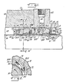
- Figure 1 is a side elevation view in section taken along a vertical center-line of a portion of the preferred embodiment of the invention.
- Figure 2 is an end view of a segment of one of the sealing rings of the preferred embodiment of the invention.
- FIG. 1 illustrates a seal designated 10 constructed in accordance with the preferred embodiment of the invention.
- the seal is designed to contain liquefied light hydrocarbons and other high vapor-pressure liquids such as liquid natural gas (LNG), liquefied petroleum gas (LPG) including methane ethylene, ethane, propane, butane and pentane within a pump housing.
- LNG liquid natural gas
- LPG liquefied petroleum gas
- the housing is indicated at 12 enclosing the pump interior 14.
- a shaft 16 extends through an opening 18 in the housing 12 to the atmosphere 20.
- the seal 10 has a tandem arrangement of spiral groove mechanical end face seals, each having portions mounted on the housing and shaft.
- the seals are generally of the type shown in the U.S. patent no. 4.212.475 referred to above.
- the tandem seals include an upstream or inside seal module 22 and a downstream or outside seal module 24 which define an annular chamber 25 between them.
- Each seal module has a pair of annular rings comprising primary rings 26A, 26B with radially extending faces 28A, 28B and mating rings 30A, 30B having radially extending faces 32A, 32B opposite the faces 28A, 28B of the primary rings.
- the primary rings 26A, 26B are affixed to the housing by a retainer assembly.
- the mating rings 30A, 30B are affixed for rotation with the shaft 16 by a sleeve assembly.
- the seal shown is exposed to a fluid to be sealed at the radially outer diameter of the seal components.
- the principles of the invention are applicable to seals having the high pressure at the radially inner diameter of the relatively rotating seal faces.
- the sleeve assembly includes a shaft sleeve 34 which fits upon the shaft 16 and is held against rotation by a drive key 36.
- Sleeve 34 is fixed to the shaft to prevent outward axial motion of the sleeve by appropriate means (not shown).
- An O-ring is also positioned at this flange to seal between the sleeve and shaft.
- the upstream seal module 22 includes a support 38 positioned by an annular split wedge 40 which in turn is held by a clamping ring 42.
- a cap screw 44 connects the clamping ring 42 and mating ring support 38 to compress wedge 40 against sleeve 34.
- a pin 46 connects the mating ring 30A to the mating ring support 38.
- O-rings are provided as shown on the mating ring support.
- the sleeve assembly further includes a spacer sleeve 48 which includes a support flange 50, which holds a pin 46 to engage and drive the mating ring 30B of the outboard seal module 24. Again, O-rings are supplied on the flange 50 as shown.
- the spacer sleeve 48 extends to and engages the radial surface 32A adjacent the inside diameter of the mating ring 30A. Thus, the mating rings 30A, 30B and their respective supports 38 and 50 are locked between the wedge 40 and a shoulder 52 on the shaft sleeve 34.
- the retainer assembly comprises inboard and outboard retainers 54 and 56 connected by cap screws 57.
- the inboard retainer 54 mounts the inboard primary ring 26A.
- the outboard retainer 56 similarly mounts the outboard primary ring 26B.
- Each retainer carries multiple springs 58 and disks 60 which urge the primary rings into engagement with the mating rings.
- the disks 60 and springs 58 permit primary rings 26A and 26B to move axially of the shaft.
- O-ring seals 61 provide a secondary seal between disks 60 and retainers 54 and 56.
- a gland plate 62 connects to housing 12.
- the plate is attached to the housing by screws (not shown).
- the gland plate has a flange 64 engaging the outer end face of the retainer 56.
- the retainer is connected to the flange by cap screws 66.
- Suitable O-rings are provided as shown to seal the gland plate against the housing 12 and retainers 54, 56.
- a vent passage 68 communicates with an opening 70 in the retainer 56 and chamber 25.
- the vent 68 is connectable to a flare stack or other combustion apparatus for disposing of the controlled amount of gas passing across the rotating faces of upstream seal module 24.
- gas may, for example, be used for heating buildings associated with the apparatus containing the seal or recompressed for other uses.
- Figure 2 shows a portion of a mating surface on either the mating ring or primary ring.
- the face 32A of mating ring 30A is shown.
- the face has a plurality of pumping spiral grooves 72 extending from the outer circumference partailly across the width of the face 32A.
- the ungrooved surface 73 defines a sealing dam which provides a contacting static seal when the seal faces are not rotating relative to each other.
- Face 32B is similarly configured. It has been found that the depth of the grooves on the inside and outside seal modules is critical to acceptable performance when sealing against high vapor-pressure liquids such as light hydrocarbons.
- the groove depth of the upstream seal module should be substantially less than that preferred for dry running gas seals as defined in the aforementioned U.S. patent no. 4.212.475, and should not exceed 26 x 10 ⁇ 4 mm (100 micro-inches).
- the groove depth of the grooves of the downstream module should be greater than the groove depth of the upstream module and should not exceed 51 x 10 ⁇ 4 mm (200 micro-inches).
- a specific embodiment found to give superior results has an upstream seal module ring groove depth of 13 x 10 ⁇ 4 mm (50 micro-inches) and a downstream module ring groove depth of 26 x 10 ⁇ 4 mm (100 micro-inches).
- Such a seal has been successful in a LNG plant pump operating at 2.800 kN/m2 over-pressure (400 psig), 3600 rpm, 52°C (125°F), 71 mm (2-7/8 inch) shaft diameter with a fluid of 50.5 molecular weight and a vapor pressure of 2.700 kN/m2 over-pressure (390 psig) at 73°C (161°F).
- upstream module groove depth is as much as 26 x 10 ⁇ 4 mm (100 micro-inches) and the downstream module groove depth being as much as 51 x 10 ⁇ 4 mm (200 micro-inches).
- the preferred groove depth of the upstream module should be no more than about 13 x 10 ⁇ 4 mm (50 micro-inches), and the preferred groove depth of the downstream module should be no more than about 26 x 10 ⁇ 4 mm (100 micro-inches).
- the groove depth at the first seal module is reduced from that heretofore in dry running gas seals. This restricts the flow of liquid across the first module seal interface, thereby increasing the shear stress applied to the liquid.
- the first seal operates as a means for changing phase from liquid to gas. It is contemplated that this module need not be in a configuration of a dry running gas seal but could be any shear imparting element between the housing and shaft. It is believed that the large shearing action causes stress applied at the first seal module to create a temperature rise which in turn causes a change of phase of the sealed fluid from liquid to gas. The first module thus acts as a heat input component.
- the second seal module 24 operates as a dry running gas seal, much as described in the aforementioned U.S. patent no. 4.212.475, to prevent leakage beyond the gland plate 62.
- the net effect of the tandem arrangement is that the inside seal module contains the liquid by adding heat to that quantity which passes across the faces 28A, 32A and converts it to gas, and the outside seal module seals against escape of the gas phase of the fluid.
Landscapes
- Engineering & Computer Science (AREA)
- General Engineering & Computer Science (AREA)
- Mechanical Engineering (AREA)
- Mechanical Sealing (AREA)
- Sealing Using Fluids, Sealing Without Contact, And Removal Of Oil (AREA)
Abstract
Claims (16)
- Système d'étanchéité tandem à gorges spiralées pour assurer l'étanchéité d'un arbre tournant (16) passant à travers un boîtier (12) pour éviter la fuite du liquide renfermé, le système comportant des modules espacés l'un de l'autre amont et aval (22, 24), ledit module amont (22) comportant une bague primaire (26A) fixée de façon étanche au boîtier (12) et une bague correspondante (30A) fixée à l'arbre (16), les bagues (26A, 30A) comportant des faces opposées s'étendant radialement (28A, 32A), l'une desquelles comporte des gorges spiralées de pompage (72) s'étendant vers l'intérieur à partir d'une circonférence de la face, ledit module aval (24) comportant également une bague primaire (26B) fixée de façon étanche au boîtier (12) et une bague correspondante (30B) fixée à l'arbre (16), les bagues (26B, 30B) comportant des faces s'étendant radialement opposées (28B, 32B) l'une desquelles comporte un ensemble de gorges spiralées de pompage s'étendant vers l'intérieur à partir d'une circonférence de la face, caractérisé en ce que la profondeur de gorge des gorges dudit module aval (24) est supérieure à la profondeur de gorge des gorges dudit module aval (24) est supérieure à la profondeur de gorge des gorges dudit module amont (22), de telle sorte que les gorges (72) du module amont (22) provoquent le changement de phase du liquide en un gaz et de telle sorte que ledit module aval (24) fonctionne comme un joint à gaz qui travaille à sec.
- Système d'étanchéité selon la revendication 1 dans lequel un passage d'évacuation (68) se trouve en communication de fluide avec la chambre annulaire (25) comprise entre les modules (22, 24) et est susceptible d'être connecté à un moyen de combustion.
- Système d'étanchéité selon la revendication 1 ou 2 dans lequel lesdites gorges dudit module d'étanchéité amont ont une profondeur qui ne dépasse pas 26 X 10⁻⁴ (100 micropouces).
- Système d'étanchéité selon la revendication 1 ou 2 dans lequel la profondeur de gorge du module d'étanchéité amont n'est pas supérieure à environ 13 X 10⁻⁴ mm (50 micropouces).
- Système d'étanchéité selon la revendication 3 dans lequel la profondeur de gorge du module d'étanchéité aval n'est pas supérieure à environ 51 X 10⁻⁴ mm (200 micropouces).
- Système d'étanchéité selon la revendication 4 dans lequel la profondeur de gorge du module d'étanchéité aval peut atteindre 26 X 10⁻⁴ mm (100 micropouces).
- Système d'étanchéité selon la revendication 1 ou 2 dans lequel la profondeur de gorge du module d'étanchéité aval peut atteindre environ 51 X 10⁻⁴ mm (200 micropouces).
- Système d'étanchéité selon la revendication 1 ou 2 dans lequel la profondeur de gorge du module d'étanchéité amont est d'environ 13 X 10⁻⁴ mm (50 micropouces) et la profondeur de gorge du module d'étanchéité aval est d'environ 26 X 10⁻⁴ mm (100 micropouces).
- Système d'étanchéité selon la revendication 1 ou 2 dans lequel la profondeur de gorge du module d'étanchéité amont est d'environ la moitié de celle du module d'étanchéité aval.
- Procédé pour assurer l'étanchéité d'un arbre (16) s'étendant à travers un boîtier (12) contre la fuite de liquide contenu qui consiste à :
prévoir un module d'étanchéité amont (22) monté sur l'arbre (16) et le boîtier (12) pour réaliser l'étanchéité par rapport au fluide contenu, ledit module d'étanchéité amont (22) comportant un joint ayant une bague primaire (26A) fixée au boîtier (12) et une bague correspondante (30A) fixée à l'arbre (16), les bagues (26A, 30A) ayant des faces opposées s'étendant radialement (28A, 32A), l'une desquelles comporte un ensemble de gorges spiralées de pompage (72) s'étendant à partir d'une circonférence de celles-ci, lesdites gorges spiralées de pompage (72) du module amont (22) ayant une première profondeur de gorge prédéterminée ;
prévoir un module d'étanchéité aval (24) monté sur l'arbre (16) et le boîtier (12) en aval du module amont (22), le module d'étanchéité aval (24) comportant un joint qui a une bague primaire (26) fixée au boîtier (12) et une bague correspondante (30B) fixée à l'arbre (16), les bagues ayant des faces opposées s'étendant radialement (28A, 32A) l'une desquelles comporte un ensemble de gorges spiralées de pompage s'étendant à partir d'une circonférence de cette dernière, lesdites gorges spiralées de pompage du module aval (24) ayant une seconde profondeur de gorge prédéterminée qui est supérieure à ladite première profondeur de gorge prédéterminée ; lesdites gorges spiralées de pompage (72) du module amont (22) provoquant un changement de phase du liquide pour qu'il devienne gazeux et ledit module aval (24) fonctionnant comme un joint travaillant à sec. - Procédé selon la revendication 10 dans lequel la profondeur de gorge desdites gorges spiralées de pompage (72) du module amont (22) n'est pas supérieure à 13 X 10⁻⁴ mm (50 micropouces).
- Procédé selon la revendication 10 dans lequel la profondeur de gorge desdites gorges spiralées de pompage du module aval (24) n'est pas supérieure à 51 X 10⁻⁴ mm (200 micropouses).
- Procédé selon la revendication 10 dans lequel la profondeur de gorge desdites gorges spiralées de pompage (72) du module amont (22) est d'environ 13 X 10⁻⁴ mm (50 micropouces) et la profondeur de gorge desdites gorges spiralées de pompage du module aval (24) est d'environ 26 X 10⁻⁴ mm (100 micropouces).
- Procédé selon la revendication 4 caractérisé en outre en ce que les gorges spiralées de pompage (72) du module amont (22) provoquent un changement de phase du liquide pour qu'il devienne gazeux par addition de chaleur au fluide.
- Procédé selon la revendication 14 caractérisé en outre en ce que la chaleur est engendrée par cisaillement du fluide.
- Procédé selon la revendication 10 comportant en outre la consommation du gaz qui s'échappe à travers les gorges spiralées de pompage (72) du module amont (22).
Priority Applications (1)
| Application Number | Priority Date | Filing Date | Title |
|---|---|---|---|
| AT88906374T ATE93941T1 (de) | 1987-06-10 | 1988-06-10 | Dichtungsanordnung mit spiralfoermiger nute fuer fluessigkeiten mit hohem dampfdruck. |
Applications Claiming Priority (2)
| Application Number | Priority Date | Filing Date | Title |
|---|---|---|---|
| US07/060,215 US4889348A (en) | 1987-06-10 | 1987-06-10 | Spiral groove seal system for high vapor-pressure liquids |
| US60215 | 1987-06-10 |
Publications (3)
| Publication Number | Publication Date |
|---|---|
| EP0363434A4 EP0363434A4 (fr) | 1990-04-10 |
| EP0363434A1 EP0363434A1 (fr) | 1990-04-18 |
| EP0363434B1 true EP0363434B1 (fr) | 1993-09-01 |
Family
ID=22028080
Family Applications (1)
| Application Number | Title | Priority Date | Filing Date |
|---|---|---|---|
| EP88906374A Expired - Lifetime EP0363434B1 (fr) | 1987-06-10 | 1988-06-10 | Systeme d'etancheite a gorge spiralee pour liquides a haute pression de vapeur |
Country Status (7)
| Country | Link |
|---|---|
| US (1) | US4889348A (fr) |
| EP (1) | EP0363434B1 (fr) |
| JP (1) | JP2728283B2 (fr) |
| KR (1) | KR900700801A (fr) |
| CA (1) | CA1300186C (fr) |
| DE (1) | DE3883766T2 (fr) |
| WO (1) | WO1988009891A1 (fr) |
Families Citing this family (67)
| Publication number | Priority date | Publication date | Assignee | Title |
|---|---|---|---|---|
| DE3901362A1 (de) * | 1989-01-18 | 1990-07-19 | Burgmann Dichtungswerk Feodor | Gleitringdichtung zur abdichtung eines gasfoermigen mediums |
| US5217233A (en) * | 1989-10-30 | 1993-06-08 | John Crane Inc. | Spiral groove seal system for sealing a high pressure gas |
| US5039113A (en) * | 1990-01-17 | 1991-08-13 | Eg&G Sealol, Inc. | Spiral groove gas lubricated seal |
| US5249812A (en) * | 1990-03-12 | 1993-10-05 | John Crane Inc. | Barrier seal systems |
| US5137284A (en) * | 1990-03-16 | 1992-08-11 | Stein Seal Company | Stationary seal ring assembly for use in dry gas face seal assemblies |
| US5253876A (en) * | 1990-03-28 | 1993-10-19 | Eg&G Sealol, Inc. | System and method for actively cooling dry-running gas seals |
| US5071141A (en) * | 1990-07-17 | 1991-12-10 | John Crane Inc. | Spiral groove seal arrangement for high vapor-pressure liquids |
| US5203575A (en) * | 1990-11-28 | 1993-04-20 | Awchesterton Company | Balanced mechanical seal assembly and flow ring therefor |
| WO1992012366A1 (fr) * | 1991-01-11 | 1992-07-23 | Bw/Ip International, Inc. | Ensemble d'etanchement biphase |
| GB9103217D0 (en) * | 1991-02-15 | 1991-04-03 | Crane John Uk Ltd | Mechanical face seals |
| JPH07504959A (ja) * | 1991-11-12 | 1995-06-01 | ビーダブリュー/アイピー・インターナショナル・インコーポレーテッド | 副ガス/液体メカニカルシール組立体 |
| US5722665A (en) * | 1992-02-26 | 1998-03-03 | Durametallic Corporation | Spiral groove face seal |
| US5172918A (en) * | 1992-04-28 | 1992-12-22 | John Crane Inc. | Secondary seal for gas turbines |
| GB9214282D0 (en) * | 1992-07-04 | 1992-08-19 | Crane John Uk Ltd | Seals |
| US5544897A (en) * | 1993-08-19 | 1996-08-13 | A. W. Chesterton Co. | Cartridge seal having a high contact pressure seal and means for intersleeve adjustment including quench fluid delivery |
| AU685502B2 (en) * | 1993-09-01 | 1998-01-22 | Durametallic Corporation | Face seal with angled and annular grooves |
| US5529315A (en) * | 1994-02-14 | 1996-06-25 | John Crane Inc. | Tandem seal arrangement for mechanical face seals |
| US5639097A (en) * | 1994-12-09 | 1997-06-17 | Eg&G Sealol, Inc. | Gas seal "O" ring holder |
| DE19501900A1 (de) * | 1995-01-23 | 1996-07-25 | Klein Schanzlin & Becker Ag | Gleitringdichtung für Kesselspeisepumpen |
| US5941532A (en) * | 1996-06-20 | 1999-08-24 | Rexnord Corporation | Aerospace housing and shaft assembly with noncontacting seal |
| US5873574A (en) * | 1996-07-18 | 1999-02-23 | John Crane Sealol Inc. | Bellows seal with reverse pressure capability |
| SE518871C2 (sv) * | 1996-11-14 | 2002-12-03 | Flygt Ab Itt | Plantätningsarrangemang |
| US5934683A (en) * | 1997-07-10 | 1999-08-10 | Roy E. Roth Company | Rotary seal assembly having grooved seal facing |
| AU1924299A (en) | 1997-12-17 | 1999-07-05 | A.W. Chesterton Company | Fluidic feedback pressure regulation system for a mechanical seal |
| US6120034A (en) | 1997-12-17 | 2000-09-19 | A.W. Chesterston Company | Secondary sealing assembly for mechanical face seal |
| US6059293A (en) * | 1997-12-17 | 2000-05-09 | A.W. Chesterton Company | Split mechanical face seal with seal face fluid introducing structure |
| US6267382B1 (en) * | 1998-02-23 | 2001-07-31 | Dresser-Rand Company | Fail safe L-shaped spring carrier for gas seals |
| DE29806905U1 (de) * | 1998-04-16 | 1998-07-09 | Feodor Burgmann Dichtungswerke GmbH & Co, 82515 Wolfratshausen | Gleitringdichtungsanordnung, insbesondere für die Flüssiggasabdichtung |
| US6454268B1 (en) | 2001-02-09 | 2002-09-24 | Eagle Industry Co., Ltd. | Shaft seal device |
| US6969236B2 (en) * | 2003-08-29 | 2005-11-29 | Honeywell International, Inc. | Fluid-cooled mechanical face seal rotor |
| US20060207834A1 (en) * | 2005-03-03 | 2006-09-21 | Honeywell International, Inc. | Aircraft engine accessory drive air film riding bulkhead seal |
| US9897213B2 (en) * | 2005-03-31 | 2018-02-20 | Aes Engineering Ltd. | Flow inducing ring for a mechanical seal |
| EP2881633B1 (fr) * | 2012-08-04 | 2017-11-08 | Eagle Industry Co., Ltd. | Composant de coulissement |
| GB201214472D0 (en) * | 2012-08-14 | 2012-09-26 | Rolls Royce Plc | Intershaft seal |
| FR3000167B1 (fr) * | 2012-12-20 | 2015-08-21 | Cryostar Sas | Ensemble joint d'etancheite a gaz pour pompes a liquide cryogenique |
| DE102013227208A1 (de) * | 2013-12-30 | 2015-07-02 | Siemens Aktiengesellschaft | Dichtsystem für eine Dampfturbine sowie Dampfturbine |
| EP3499098B1 (fr) | 2016-08-15 | 2024-04-24 | Eagle Industry Co., Ltd. | Composant coulissant |
| USRE50849E1 (en) | 2016-11-16 | 2026-03-31 | Eagle Industry Co., Ltd. | Sliding component |
| JP7179430B2 (ja) | 2018-01-12 | 2022-11-29 | イーグル工業株式会社 | 摺動部品 |
| CN108087559B (zh) * | 2018-01-17 | 2023-06-02 | 中国船舶重工集团公司第七〇四研究所 | 吊舱推进器用艉密封装置 |
| EP3748205B1 (fr) | 2018-02-01 | 2024-12-18 | Eagle Industry Co., Ltd. | Pièces coulissantes |
| JP7387239B2 (ja) | 2019-02-04 | 2023-11-28 | イーグル工業株式会社 | 摺動部品 |
| KR102610648B1 (ko) | 2019-02-04 | 2023-12-07 | 이구루코교 가부시기가이샤 | 슬라이딩 부품 및 슬라이딩 부품의 제조 방법 |
| CN115853894A (zh) | 2019-02-04 | 2023-03-28 | 伊格尔工业股份有限公司 | 滑动部件 |
| CN113348307B (zh) * | 2019-02-04 | 2023-11-14 | 伊格尔工业股份有限公司 | 滑动部件 |
| WO2020162349A1 (fr) | 2019-02-04 | 2020-08-13 | イーグル工業株式会社 | Élément coulissant |
| US11852241B2 (en) | 2019-02-04 | 2023-12-26 | Eagle Industry Co., Ltd. | Sliding component |
| WO2020166589A1 (fr) | 2019-02-14 | 2020-08-20 | イーグル工業株式会社 | Composants coulissants |
| EP3926188B1 (fr) | 2019-02-15 | 2024-08-21 | Eagle Industry Co., Ltd. | Éléments coulissants |
| JP7419346B2 (ja) | 2019-03-22 | 2024-01-22 | イーグル工業株式会社 | 摺動部品 |
| CA3149414A1 (fr) * | 2019-09-06 | 2021-03-11 | James R. Wasser | Joint d'etancheite a gaz sec sans poussee avec elastomere d'etancheite et systemes l'utilisant |
| JP7480278B2 (ja) | 2020-03-31 | 2024-05-09 | イーグル工業株式会社 | 摺動部品 |
| KR102798715B1 (ko) | 2020-05-11 | 2025-04-23 | 이구루코교 가부시기가이샤 | 슬라이딩 부품 |
| KR102877441B1 (ko) | 2020-07-06 | 2025-10-29 | 이구루코교 가부시기가이샤 | 회전 기계 |
| CN115917192A (zh) | 2020-07-06 | 2023-04-04 | 伊格尔工业股份有限公司 | 滑动部件 |
| JP7700121B2 (ja) | 2020-07-06 | 2025-06-30 | イーグル工業株式会社 | 摺動部品 |
| WO2022009767A1 (fr) | 2020-07-06 | 2022-01-13 | イーグル工業株式会社 | Élément coulissant |
| JP7475801B2 (ja) | 2020-07-06 | 2024-04-30 | イーグル工業株式会社 | 摺動部品 |
| US12404935B2 (en) | 2020-07-06 | 2025-09-02 | Eagle Industry Co., Ltd. | Sliding component |
| CN116324237B (zh) | 2020-09-29 | 2026-06-12 | 伊格尔工业股份有限公司 | 滑动部件 |
| EP4230899A4 (fr) | 2020-10-14 | 2024-11-20 | Eagle Industry Co., Ltd. | Composant coulissant |
| DE102020127710A1 (de) * | 2020-10-21 | 2022-04-21 | Rolls-Royce Deutschland Ltd & Co Kg | Vorrichtung mit wenigstens zwei Bauteilen und Gasturbinentriebwerk mit einer solchen Vorrichtung |
| US12560239B2 (en) | 2021-08-25 | 2026-02-24 | Eagle Industry Co., Ltd. | Sliding components |
| JP7842769B2 (ja) | 2021-08-26 | 2026-04-08 | イーグル工業株式会社 | 摺動部品 |
| JP2025505716A (ja) * | 2022-02-17 | 2025-02-28 | エー. ダブリュー. チェスタートン カンパニー | エラストマーばね式メカニカルシール |
| DE102023101276B3 (de) | 2022-08-08 | 2023-09-07 | Audi Aktiengesellschaft | Dichtungssystem mit Fluid-Kühlfunktion für ein Fluidbehältnis, Behältnis mit Dichtungssystem und Kraftfahrzeug mit Behältnis |
| CN115875457B (zh) * | 2022-12-01 | 2023-08-08 | 浙江工业大学 | 一种带疏液功能表面的天然气干气密封环结构 |
Citations (1)
| Publication number | Priority date | Publication date | Assignee | Title |
|---|---|---|---|---|
| US4290611A (en) * | 1980-03-31 | 1981-09-22 | Crane Packing Co. | High pressure upstream pumping seal combination |
Family Cites Families (7)
| Publication number | Priority date | Publication date | Assignee | Title |
|---|---|---|---|---|
| CA550642A (fr) * | 1957-12-24 | Herbert E. Michener, Jr. | Dispositif d'etancheite d'arbre | |
| BE551346A (fr) * | 1955-09-29 | |||
| US3499653A (en) * | 1968-06-05 | 1970-03-10 | Crane Packing Co | Rotary mechanical seal of the gap type |
| US3704019A (en) * | 1970-06-19 | 1972-11-28 | Gen Electric | Spiral groove face seals |
| DE2156953C3 (de) * | 1971-11-17 | 1974-10-10 | Klein, Schanzlin & Becker Ag, 6710 Frankenthal | Wellenabdichtung für Reaktorumwälzpumpen |
| US4212475A (en) * | 1979-01-15 | 1980-07-15 | Crane Packing Co. | Self aligning spiral groove face seal |
| DK171954B1 (da) * | 1980-11-04 | 1997-08-25 | Eagle Ind Co Ltd | Mekanisk taetning og fremgangsmaader ved fremstilling af en i taetningen indgaaende glideflade |
-
1987
- 1987-06-10 US US07/060,215 patent/US4889348A/en not_active Expired - Lifetime
-
1988
- 1988-06-10 KR KR1019890700211A patent/KR900700801A/ko not_active Ceased
- 1988-06-10 DE DE88906374T patent/DE3883766T2/de not_active Expired - Fee Related
- 1988-06-10 EP EP88906374A patent/EP0363434B1/fr not_active Expired - Lifetime
- 1988-06-10 CA CA000569285A patent/CA1300186C/fr not_active Expired - Lifetime
- 1988-06-10 JP JP63505630A patent/JP2728283B2/ja not_active Expired - Fee Related
- 1988-06-10 WO PCT/US1988/001993 patent/WO1988009891A1/fr not_active Ceased
Patent Citations (1)
| Publication number | Priority date | Publication date | Assignee | Title |
|---|---|---|---|---|
| US4290611A (en) * | 1980-03-31 | 1981-09-22 | Crane Packing Co. | High pressure upstream pumping seal combination |
Also Published As
| Publication number | Publication date |
|---|---|
| DE3883766T2 (de) | 1993-12-09 |
| US4889348A (en) | 1989-12-26 |
| DE3883766D1 (de) | 1993-10-07 |
| EP0363434A1 (fr) | 1990-04-18 |
| KR900700801A (ko) | 1990-08-17 |
| CA1300186C (fr) | 1992-05-05 |
| EP0363434A4 (fr) | 1990-04-10 |
| JPH02503945A (ja) | 1990-11-15 |
| WO1988009891A1 (fr) | 1988-12-15 |
| JP2728283B2 (ja) | 1998-03-18 |
Similar Documents
| Publication | Publication Date | Title |
|---|---|---|
| US4889348A (en) | Spiral groove seal system for high vapor-pressure liquids | |
| EP0470406B1 (fr) | Dispositif d'étanchéité à gorge spiralée pour liquides à haute pression de vapeur | |
| EP0426041B1 (fr) | Système d'étanchéité à gorge spiralée pour gaz sous haute pression | |
| US5454572A (en) | Mechanical end face seal system | |
| CA2097367C (fr) | Joint mecanique d'extremite | |
| EP0447898B1 (fr) | Etanchement de barrière de fluide | |
| US4290611A (en) | High pressure upstream pumping seal combination | |
| US5529315A (en) | Tandem seal arrangement for mechanical face seals | |
| EP0013678B1 (fr) | Joint d'étanchéité mécanique muni de gorges en spirale, à auto-rétablissement de la position relative | |
| US3806135A (en) | Cooling seal | |
| US20020074731A1 (en) | Rotary sealing assembly | |
| KR19990007890A (ko) | 샤프트 밀봉 | |
| EP0223457B1 (fr) | Garnitures étanches mécaniques | |
| AU626266B2 (en) | Spiral-groove seal system for high vapor-pressure liquids | |
| US4795169A (en) | Radially stable mechanical face seals | |
| Shah | Dry Gas Compressor Seals | |
| GB2182400A (en) | Seals between relatively rotatable components | |
| GB2037905A (en) | Seals |
Legal Events
| Date | Code | Title | Description |
|---|---|---|---|
| PUAI | Public reference made under article 153(3) epc to a published international application that has entered the european phase |
Free format text: ORIGINAL CODE: 0009012 |
|
| 17P | Request for examination filed |
Effective date: 19891207 |
|
| AK | Designated contracting states |
Kind code of ref document: A1 Designated state(s): AT BE CH DE FR GB IT LI LU NL SE |
|
| A4 | Supplementary search report drawn up and despatched |
Effective date: 19900410 |
|
| 17Q | First examination report despatched |
Effective date: 19920226 |
|
| GRAA | (expected) grant |
Free format text: ORIGINAL CODE: 0009210 |
|
| AK | Designated contracting states |
Kind code of ref document: B1 Designated state(s): AT BE CH DE FR GB IT LI LU NL SE |
|
| PG25 | Lapsed in a contracting state [announced via postgrant information from national office to epo] |
Ref country code: LI Effective date: 19930901 Ref country code: CH Effective date: 19930901 |
|
| REF | Corresponds to: |
Ref document number: 93941 Country of ref document: AT Date of ref document: 19930915 Kind code of ref document: T |
|
| REF | Corresponds to: |
Ref document number: 3883766 Country of ref document: DE Date of ref document: 19931007 |
|
| ITF | It: translation for a ep patent filed | ||
| REG | Reference to a national code |
Ref country code: CH Ref legal event code: PL |
|
| ET | Fr: translation filed | ||
| PGFP | Annual fee paid to national office [announced via postgrant information from national office to epo] |
Ref country code: AT Payment date: 19940426 Year of fee payment: 7 |
|
| PGFP | Annual fee paid to national office [announced via postgrant information from national office to epo] |
Ref country code: BE Payment date: 19940608 Year of fee payment: 7 |
|
| PGFP | Annual fee paid to national office [announced via postgrant information from national office to epo] |
Ref country code: SE Payment date: 19940617 Year of fee payment: 7 |
|
| PG25 | Lapsed in a contracting state [announced via postgrant information from national office to epo] |
Ref country code: LU Free format text: LAPSE BECAUSE OF NON-PAYMENT OF DUE FEES Effective date: 19940630 |
|
| PLBE | No opposition filed within time limit |
Free format text: ORIGINAL CODE: 0009261 |
|
| STAA | Information on the status of an ep patent application or granted ep patent |
Free format text: STATUS: NO OPPOSITION FILED WITHIN TIME LIMIT |
|
| 26N | No opposition filed | ||
| EAL | Se: european patent in force in sweden |
Ref document number: 88906374.9 |
|
| PG25 | Lapsed in a contracting state [announced via postgrant information from national office to epo] |
Ref country code: AT Effective date: 19950610 |
|
| PG25 | Lapsed in a contracting state [announced via postgrant information from national office to epo] |
Ref country code: SE Effective date: 19950611 |
|
| PGFP | Annual fee paid to national office [announced via postgrant information from national office to epo] |
Ref country code: NL Payment date: 19950629 Year of fee payment: 8 |
|
| PG25 | Lapsed in a contracting state [announced via postgrant information from national office to epo] |
Ref country code: BE Effective date: 19950630 |
|
| BERE | Be: lapsed |
Owner name: JOHN CRANE INC. Effective date: 19950630 |
|
| EUG | Se: european patent has lapsed |
Ref document number: 88906374.9 |
|
| PG25 | Lapsed in a contracting state [announced via postgrant information from national office to epo] |
Ref country code: NL Effective date: 19970101 |
|
| NLV4 | Nl: lapsed or anulled due to non-payment of the annual fee |
Effective date: 19970101 |
|
| REG | Reference to a national code |
Ref country code: GB Ref legal event code: IF02 |
|
| PGFP | Annual fee paid to national office [announced via postgrant information from national office to epo] |
Ref country code: GB Payment date: 20020513 Year of fee payment: 15 |
|
| PGFP | Annual fee paid to national office [announced via postgrant information from national office to epo] |
Ref country code: DE Payment date: 20020621 Year of fee payment: 15 |
|
| PGFP | Annual fee paid to national office [announced via postgrant information from national office to epo] |
Ref country code: FR Payment date: 20020624 Year of fee payment: 15 |
|
| PG25 | Lapsed in a contracting state [announced via postgrant information from national office to epo] |
Ref country code: GB Free format text: LAPSE BECAUSE OF NON-PAYMENT OF DUE FEES Effective date: 20030610 |
|
| PG25 | Lapsed in a contracting state [announced via postgrant information from national office to epo] |
Ref country code: DE Free format text: LAPSE BECAUSE OF NON-PAYMENT OF DUE FEES Effective date: 20040101 |
|
| GBPC | Gb: european patent ceased through non-payment of renewal fee |
Effective date: 20030610 |
|
| PG25 | Lapsed in a contracting state [announced via postgrant information from national office to epo] |
Ref country code: FR Free format text: LAPSE BECAUSE OF NON-PAYMENT OF DUE FEES Effective date: 20040227 |
|
| REG | Reference to a national code |
Ref country code: FR Ref legal event code: ST |
|
| PG25 | Lapsed in a contracting state [announced via postgrant information from national office to epo] |
Ref country code: IT Free format text: LAPSE BECAUSE OF NON-PAYMENT OF DUE FEES;WARNING: LAPSES OF ITALIAN PATENTS WITH EFFECTIVE DATE BEFORE 2007 MAY HAVE OCCURRED AT ANY TIME BEFORE 2007. THE CORRECT EFFECTIVE DATE MAY BE DIFFERENT FROM THE ONE RECORDED. Effective date: 20050610 |
|
| P01 | Opt-out of the competence of the unified patent court (upc) registered |
Effective date: 20230522 |