EP0363514B1 - Méthode de contrôle d'un circuit utilisateur à courant triphasé par modulation d'impulsions en largeur estimant une sinusoide - Google Patents
Méthode de contrôle d'un circuit utilisateur à courant triphasé par modulation d'impulsions en largeur estimant une sinusoide Download PDFInfo
- Publication number
- EP0363514B1 EP0363514B1 EP88117056A EP88117056A EP0363514B1 EP 0363514 B1 EP0363514 B1 EP 0363514B1 EP 88117056 A EP88117056 A EP 88117056A EP 88117056 A EP88117056 A EP 88117056A EP 0363514 B1 EP0363514 B1 EP 0363514B1
- Authority
- EP
- European Patent Office
- Prior art keywords
- pulse widths
- phase
- frequency
- sine
- section
- Prior art date
- Legal status (The legal status is an assumption and is not a legal conclusion. Google has not performed a legal analysis and makes no representation as to the accuracy of the status listed.)
- Revoked
Links
- 238000000034 method Methods 0.000 title claims abstract description 37
- 238000011156 evaluation Methods 0.000 title abstract 2
- 238000004804 winding Methods 0.000 claims description 57
- 230000001360 synchronised effect Effects 0.000 claims description 2
- 238000001208 nuclear magnetic resonance pulse sequence Methods 0.000 claims 1
- 238000004904 shortening Methods 0.000 claims 1
- 238000010586 diagram Methods 0.000 description 4
- 230000010363 phase shift Effects 0.000 description 4
- 230000007423 decrease Effects 0.000 description 2
- 238000011161 development Methods 0.000 description 2
- 230000018109 developmental process Effects 0.000 description 2
- 230000004913 activation Effects 0.000 description 1
- 230000015572 biosynthetic process Effects 0.000 description 1
- 230000001419 dependent effect Effects 0.000 description 1
- 230000000694 effects Effects 0.000 description 1
- 238000007873 sieving Methods 0.000 description 1
- 238000003786 synthesis reaction Methods 0.000 description 1
Images



Classifications
-
- H—ELECTRICITY
- H02—GENERATION; CONVERSION OR DISTRIBUTION OF ELECTRIC POWER
- H02M—APPARATUS FOR CONVERSION BETWEEN AC AND AC, BETWEEN AC AND DC, OR BETWEEN DC AND DC, AND FOR USE WITH MAINS OR SIMILAR POWER SUPPLY SYSTEMS; CONVERSION OF DC OR AC INPUT POWER INTO SURGE OUTPUT POWER; CONTROL OR REGULATION THEREOF
- H02M7/00—Conversion of AC power input into DC power output; Conversion of DC power input into AC power output
- H02M7/42—Conversion of DC power input into AC power output without possibility of reversal
- H02M7/44—Conversion of DC power input into AC power output without possibility of reversal by static converters
- H02M7/48—Conversion of DC power input into AC power output without possibility of reversal by static converters using discharge tubes with control electrode or semiconductor devices with control electrode
- H02M7/53—Conversion of DC power input into AC power output without possibility of reversal by static converters using discharge tubes with control electrode or semiconductor devices with control electrode using devices of a triode or transistor type requiring continuous application of a control signal
- H02M7/537—Conversion of DC power input into AC power output without possibility of reversal by static converters using discharge tubes with control electrode or semiconductor devices with control electrode using devices of a triode or transistor type requiring continuous application of a control signal using semiconductor devices only, e.g. single switched pulse inverters
- H02M7/5387—Conversion of DC power input into AC power output without possibility of reversal by static converters using discharge tubes with control electrode or semiconductor devices with control electrode using devices of a triode or transistor type requiring continuous application of a control signal using semiconductor devices only, e.g. single switched pulse inverters in a bridge configuration
- H02M7/53871—Conversion of DC power input into AC power output without possibility of reversal by static converters using discharge tubes with control electrode or semiconductor devices with control electrode using devices of a triode or transistor type requiring continuous application of a control signal using semiconductor devices only, e.g. single switched pulse inverters in a bridge configuration with automatic control of output voltage or current
- H02M7/53875—Conversion of DC power input into AC power output without possibility of reversal by static converters using discharge tubes with control electrode or semiconductor devices with control electrode using devices of a triode or transistor type requiring continuous application of a control signal using semiconductor devices only, e.g. single switched pulse inverters in a bridge configuration with automatic control of output voltage or current with analogue control of three-phase output
Definitions
- the invention relates to a method for controlling three-phase consumers by sinus-weighted pulse width modulation of three phases shifted by 120 ° relative to one another and a device for carrying out the method.
- a converter for three-phase motors is known from the publication Siemens Components 24, 1986, Issue 1, pages 18 to 24, as is shown in FIG. 1 of the present description.
- An intermediate circuit voltage U ZS obtained from a rectifier arrangement I is connected to the three phases of the three-phase motor III via three transistor half bridges II with a switching frequency and sinus-weighted pulse widths.
- the transistor half-bridges II are controlled by a control device IV, in which the pulse width values required for generating the sine frequency are stored.
- an entire period of the sine frequency to be generated is divided into a number of z. B. 48 support points and the respective corresponding amplitude value determined.
- the amplitude values of these interpolation points and the further 32 data words (16 each 120 °) required because of the two phase shift of 120 °, ie a total of 80 data words, are stored as data words in a memory device or in a table of a microcontroller.
- the data words are pulse width modulated in a pulse width modulator.
- the current table values are loaded into counting registers of the pulse width modulator, which are then counted to zero according to interrupt routines and are available as pulse widths at the output terminals of the control circuit.
- the interrupt routines are controlled by a clock device of the microcontroller.
- the control process is in the known publication by integrated circuits from Siemens realized.
- the integrated circuit SLE 4520 is provided as the pulse width modulator and the integrated circuit SAB 8751 or SAB 8051 as the microcontroller.
- the present invention has for its object to provide a simplified method for the synthesis of a sine-weighted three-phase pulse width modulation for three-phase current consumers and an apparatus for performing this method, by means of which both the switching frequency of the transistor half-bridges and the storage space required for the amplitude values of the sine frequency to be generated significantly is reduced.
- a device for performing the method is the subject of claim 11. Further developments of this device are the subject of the subclaims which refer back to this claim 11.
- the invention is based on the knowledge that only a few switching states exist for the three windings of a three-phase current consumer fed by a converter within a period of the sine frequency to be generated. These few switching states are repeated with reversed windings every 60 ° and thus six times within one period. Furthermore, the invention takes advantage of the fact that it does not matter whether the reference pole in the switching state of three short-circuited windings the windings are connected to positive or negative potential.
- a further advantage of the method according to the invention is above all that the switching frequency of the transistor half-bridge switches, generally relatively cost-intensive circuit breakers, can be reduced by a third, since one phase in each case remains unclocked in a 60 ° section.
- a cyclical reversal of the phase control and thus a switchover is necessary.
- the hardware e.g. register, counter, zero detector, etc.
- the third phase can be dispensed with, so that overall the chip area required for a pulse width modulator can be reduced by approximately 20% by the method according to the invention.
- FIG. 2 shows the possible switching states of a three-phase motor in a star connection. If the interchanging of the three motor windings is not taken into account, a total of three switching states can be differentiated with clocked activation of the motor windings: Either all three motor windings are connected in parallel (a) and connected to the positive or negative potential of the DC link voltage, or (b) two Windings are connected to positive and one winding to negative potential, or (c) one winding is connected to the positive and two windings to the negative potential of the DC link voltage. In the switching state with three motor windings connected in parallel (a), it does not matter whether there is positive or negative potential at the short-circuit point of the three windings.
- the third possible switching state comprises two connection points of the motor windings connected to negative potential, while one connection point lies at the positive potential of the intermediate circuit voltage.
- the three sinusoidal phase voltages A, B and C for driving the three-phase motor are pulse-width modulated in a sinus-weighted manner.
- the sine-weighted pulse width modulation limits the power loss in the converter of the control circuit and improves its overall efficiency.
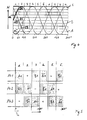
- To calculate the sinus-weighted pulse widths it is sufficient according to the invention to consider one of the 60 ° sections 1, 2, 3 ... and the phase voltages 1A, 1B, 1C or 2A, 2B, 2C etc. contained therein.
- the pulse widths Ci for the partial phase voltage 1C is set to 0, so that the phase C in the first section 1 remains unclocked from 0 to 60 °.
- Ai Kcos (Wi-60 °)
- Bi Kcos (Wi)
- the values of the pulse widths for the partial phase voltage 2B and 2C necessary for the second section 2, ie 60 ° to 120 °, are according to the invention by the inverted pulse widths Ai and Bi of the first section 1 determined.
- the partial phase voltage 2B in the second section 2 is namely inverted to the partial phase voltage 1A in the first section 1 and the partial phase voltage 2C is equal to the inverting partial phase voltage 1B .
- the first phase remains in the second section 2 A not clocked, which is advantageously set to positive potential for reasons of symmetry.
- the value for the amplitude factor AF must be changed accordingly. If the amplitude factor AF z. B. selected less than 1, the motor amplitude decreases, while at values of the amplitude factor AF greater than 1, z. B. 1.2, a limitation of the pulse width occurs.
- the necessary pulse widths Ai and Bi are advantageously generated by counting a cycle in a control device. This counting clock must be higher than the switching frequency of the pulse width modulation. The use of two independent counting cycles for the pulse widths Ai or Bi and the maximum value H for a pulse width enables the motor amplitude and motor frequency to be varied independently of one another in a simple manner.
- FIG. 5 shows the method according to the invention using an exemplary pulse diagram for driving the half bridges of the converter for each phase PH1, PH2 and PH3.
- 8 sine-weighted pulse-width modulated pulses with a switching frequency f2 of z. B. 15 kHz is provided for a section of 60 °.
- the switching frequency is 8 times lower than the maximum possible pulse width of the pulses.
- the maximum possible pulse width is limited by the switching frequency.
- a period of three-phase voltage is divided into six sections 1, 2, 3, 4, 5, 6 of 60 ° each and in one section, for. B.
- the third phase PH3 remains unclocked.
- the clock sequences consisting of the pulse widths Bi and Ai in one section are referred to in FIG. 5 as the clock sequences B1 and A1.
- the control of the three phases PH1, PH2 and PH3 is cyclically interchanged and the sine-weighted ones Pulse widths Ai and Bi of the first section on the inverted sinus-weighted pulse widths Ai and Bi inverted, i.e.
- the inverted clock sequences A1 and B1 The control in the second section 2 of the phases PH 2 and PH 3 thus takes place with the inverted sinus-weighted pulse widths Ai and Bi .
- the first phase PH1 remains unclocked and is set to positive potential for reasons of better symmetry when the phases are driven.
- the phases PH1 and PH3 are clocked, while the second phase PH2 remains unclocked and is advantageously set to negative potential.
- the control of the phases takes place with the sinus-weighted pulse widths Ai and Bi.
- the control of the three phases PH1, PH2, PH3 is again cyclically interchanged and the pulse widths used are those in vertically adjusted pulse widths Ai and Bi.
- the three phases PH1, PH2 and PH3 are activated accordingly.
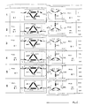
- FIG. 6 shows the method according to the invention for controlling a three-phase motor in star and delta connection for a full motor revolution.
- the connection sequence of the three motor windings MW1, MW2 and MW3 are shown in the two middle columns of FIG. 6, the delta connection on the left and the star connection on the right.
- the connection points 12, 13 and 23 between the motor windings MW1 and MW3, MW 1 and MW2, MW2 and MW3 in the delta connection and the motor windings MW1 'and MW2' and MW3 'of the star connection are in the inventive method with the already known pulse widths Ai and Bi or the associated inverted pulse widths Ai and Bi clocked.
- connection point 13 of the delta connection or the first motor winding MW1 'of the star connection is clocked from the output of the first phase PH1 by the clock sequence A1 consisting of the pulse widths Ai.
- the clock sequence B1 present at the output of the second phase PH2, consisting of the pulse widths Bi arrives the connection points 23 of the delta connection and the third motor winding MW3 'of the star connection at negative potential.
- connection point 23 becomes from the output of the third phase PH3 in accordance with the cyclical interchanging of the phase control and inverting the pulse widths in every second section with the clock sequence inverted to the clock sequence B1 B1 clocked, as well as the third winding MW3 'in the star connection.
- the connection point 13 in the delta connection for the first motor winding MW1 of the star connection is connected to the positive pole of the intermediate circuit voltage of the converter, while the connection point 12 in the delta connection and the second winding MW2 'of the star connection through the second phase PH2 with the clock sequence inverting to the clock sequence A1 A1 pulse width modulated between the positive and negative pole of the DC link voltage is switched.
- the clock sequence A1 is present at the output of the third phase PH3, which is connected to the connection point 23 of the delta connection and to the third winding MW3 of the star connection.
- the clock sequence B1 is placed over the first phase PH1 at the connection point 13 of the delta connection and the first motor winding MW1 'of the star connection.
- the connection point 12 of the delta circuit is bwz. the second motor winding MW2 'connected to the star connection.
- the fourth section between 180 ° and 240 ° is characterized by the inverted clock sequence applied to the second phase PH2 B1 , which is applied to the connection point 12 of the delta connection or to the second motor winding MW2 of the star connection.
- the inverted clock sequence at the first phase PH1 A1 is connected to the connection point 13 of the delta connection and to the first motor winding MW1 of the star connection.
- the third motor winding MW3 is connected to the positive pole of the intermediate circuit voltage in the star connection and the connection point 23 in the delta connection.
- the penultimate section 5 of a full engine period i. H. between 240 ° and 300 °, is characterized in that the connection point 13 of the delta connection and the first motor winding MW1 'of the star connection is connected to the negative potential of the intermediate circuit voltage.
- the clock sequence A1 applied to the second phase PH2 is connected to the connection point 12 of the delta connection and to the second motor winding MW2 'of the star connection.
- the clock sequence B1 on the third phase PH3 arrives at the connection point 23 of the delta connection and at the third motor winding MW3 'of the star connection.
- the inverted clock sequence appearing in the sixth section 6 between 300 ° and 360 ° at the first phase PH1 B1 is connected to the connection point 13 of the delta connection and to the first motor winding MW1 'of the star connection.
- the inverted clock sequence A1 the third phase PH3 reaches the connection point 23 of the delta connection or to the third motor winding MW3 'of the star connection.
- the connection point 12 of the delta connection and the second motor winding MW2 'of the star connection are connected.
- FIGS. 7, 8 and 9 each show the current profile in the motor winding MW3 when switched on and in the steady state with different loads.
- 7 shows the current profile through this third motor winding MW3 immediately after the switch-on process, with a motor frequency of 162 Hz, an inductance of the motor winding of 0.5 H and a resistance of the motor winding of 500 ohms.
- 8 shows the steady state.
- the phase shift between the current I and the voltage can be clearly seen. If the inductance of the motor winding is 0.08 H and the resistance R of the motor winding is 275 ohms, the phase shift is reduced, as can be seen in FIG. In addition, the lower sieving effect for the current I can be seen from the stronger zigzag shape of the current.
- FIG. 10 shows the sine-weighted pulse width modulation for the method according to the invention in a time-expanded representation.
- Each of the 60 ° sections 1, 2, 3, 4, 5 and 6 has a clock sequence with the switching frequency f2.
- 8 pulses are provided which are pulse-width modulated with the pulse widths Ai and Bi.
- the pulse widths Ai of the clock sequence A1 increase, while the pulse widths Bi for the clock sequence B1 decrease with each further of the eight pulses.
- FIG. 10 also shows the clock sequences inverted to the clock sequences A1 and B1 A1 and B1 shown how these are required to control the three phases according to the invention.
- the number of cycles in cycle sequences A1 and B1 within a 60 ° section can be freely selected. However, for a good sinusoidal current profile, it is advisable to select the highest number of cycles. It has been shown that, for. B. 8 pulses for a 60 ° section are quite sufficient. 8 pulses in a 60 ° section corresponds to a number of support points of 48 according to the previously known method. At high motor frequencies, however, the number of cycles in a section must be selected to be small, preferably less than 8. At very high motor frequencies, 8 pulses per section become too many be. The number of pulses is therefore chosen to be lower at very high motor frequencies. In contrast, 8 pulses per section will be too few at very low motor frequencies.
- FIG. 12 shows a circuit arrangement for carrying out the method according to the invention for controlling three-phase consumers.
- the circuit arrangement has three half bridges H1, H2, H3 connected in parallel, at the output terminals AG1, AG2, AG3 of which the three motor windings MW1, MW2, MW3 of a three-phase consumer DV, for. B. an asynchronous motor, a synchronous motor, are connected.
- the three half-bridges H1, H2 and H3 are connected to a rectified intermediate circuit voltage U ZS connected, by a the rectified intermediate circuit voltage U ZS ZS is supplied generating arrangement.
- a control device AS is provided for controlling the three half bridges H1, H2, H3.
- control device AS has three voltages for each phase PH1, PH2, PH3, which are connected to the control inputs of the half bridges H1, H2 and H3.
- the control device AS also has a memory device SE for storing the values for the sinus-weighted pulse widths Ai, Bi and a clock device Ti for generating the switching frequency f2 and the counting frequency f A for the values of the pulse widths Ai, Bi.
- a switching device U for cyclically interchanging the clock sequences occurring at the individual phase outputs is present in the control device AS.
- the storage device SE for the amplitude values of the support points is connected to a pulse width counter PWZ, via which the pulse widths are determined with a counting frequency f A supplied via a second input terminal E2.
- the memory device SE is additionally connected to the clock device Ti, to which the switching frequency f2 is externally supplied via a first input terminal E1.
- the control device AS also has a multiplier device VE, via which the number of pulse repetitions is realized. This is the multiplier facility VE connected to a third input terminal E3, on which the desired number of pulse repetitions can be specified externally. Furthermore, the multiplier device VE is connected to the pulse width counter PWZ and the clock device Ti.
- the sine-weighted pulse widths Ai and Bi can be converted to the inverted pulse widths via an inverting device IE contained in the control circuit AS Ai and Bi be inverted. With the help of the switching device U, the outputs of the three phases PH1, PH2 and PH3 with the pulse widths Ai, Bi, Ai , Bi be clocked.
- a logic circuit LS ensures that each phase PH1, PH2 and PH3 additionally as inverted phases PH1 , PH2 and PH3 are available so that the two switches of a half-bridge H1, H2, H3 can be controlled in phase opposition.
Landscapes
- Engineering & Computer Science (AREA)
- Power Engineering (AREA)
- Control Of Ac Motors In General (AREA)
- Ac-Ac Conversion (AREA)
- Inverter Devices (AREA)
Claims (16)
- Procédé pour commander des appareils d'utilisation triphasés au moyen d'une modulation d'impulsions en durée, à pondération sinusoïdale, de trois phases décalées réciproquement de 120°, caractérisé par le fait qu'une période de la tension triphasée devant être produite est subdivisée en six sections (1,2,3,4,5,6) de chacune 60°, que dans une première section (1), une première phase (PH1) est commandée de façon cadencée avec une fréquence de commutation (f2) et des durées d'impulsions (Ai) à pondération sinusoïdale et une seconde phase (PH2) est commandée de façon cadencée avec la fréquence de commutation (f2) et des durées d'impulsions (Bi) à pondération sinusoïdale, qu'une troisième phase (PH3) reste non commandée de façon cadencée, que la commande des trois phases (PH1, PH2, PH3) dans des sections successives (1,2,3...) est permutée cycliquement et que dans chaque seconde section (2,4,6), la commande cadencée est exécutée avec des durées d'impulsions (
Ai ,Bi ) à pondération sinusoïdale, inversées par rapport aux durées d'impulsions (Ai, Bi) à pondération sinusoïdale. - Procédé suivant la revendication 1, caractérisé par le fait que les durées d'impulsions (Ai) sont déterminées par Ai = K . cos (Wi - 60°) et que les durées d'impulsions (Bi) sont déterminées par Bi = K . cos (Wi), K étant une constante et Wi l'angle d'un point d'appui i dont la fréquence (f1) de la tension triphasée devant être produite.
- Procédé suivant la revendication 1 ou 2, caractérisé par le fait que la phase, qui respectivement n'est pas commandée de façon cadencée dans une section (1,2,3,...) est placée alternativement à un potentiel positif et à un potentiel négatif.
- Procédé suivant l'une des revendications 1 à 3, caractérisé par le fait que les durées d'impulsions (Ai) et les durées d'impulsions (Bi) et les durées d'impulsions inverses des précédentes (
Ai etBi ) sont formées par comptage d'au moins une cadence, qui possède une fréquence supérieure à la fréquence de commutation (f2). - Procédé suivant l'une des revendications 1 à 4, caractérisé par le fait que la fréquence (f1) de la tension triphasée devant être produite est modifiée par multiplication des durées d'impulsions (Ai) et des durées d'impulsions (Bi) avec un facteur (M).
- Procédé suivant l'une des revendications 1 à 5, caractérisé par le fait que l'amplitude de la fréquence (f1) de la tension triphasée devant être produite est modifiée par modification de la fréquence de commutation (f2).
- Procédé suivant l'une des revendications 1 à 6, caractérisé par le fait que le nombre des durées d'impulsions (Ai, Bi) de pondération sinusoïdale peut être choisi librement.
- Procédé suivant l'une des revendications 1 à 6, caractérisé par le fait que pour réduire la séquence des impulsions, les impulsions possédant les mêmes durées (Ai) et les impulsions possédant les durées (Bi) sont répétées au moins deux fois.
- Procédé suivant l'une des revendications 1 à 8, caractérisé par son application à la commande de moteurs asynchrones.
- Procédé suivant l'une des revendications 1 à 8, caractérisé par son application à la commande de moteurs synchrones.
- Dispositif pour la mise en oeuvre du procédé suivant l'une des revendications 1 à 10, caractérisé par les particularités suivantes :- trois demi-ponts (H1,H2,H3), qui sont branchés en parallèle et aux bornes de sortie (AG1, AG2, AG3) desquelles sont raccordés les trois enroulements (MW1, MW2, MW3) d'un appareil d'utilisation triphasé (DV),- un dispositif (ZS), qui alimente les trois demi-ponts (H1, H2, H3) avec une tension redressée de circuit intermédiaire (UZS),- un dispositif de commande (AS) servant à commander les trois demi-ponts (H1,H2,H3), comportant un dispositif de mémoire (SE) servant à mémoriser les valeurs pour les durées d'impulsions (Ai,Bi) à pondération sinusoïdale, à un dispositif de commande (Ti) servant à produire la fréquence de commutation (f2) et la fréquence de décomptage (f3) pour les valeurs des durées d'impulsions (Ai,Bi) et un dispositif de commutation (U) pour permuter cycliquement la commande des trois demi-ponts (H1,H2,H3).
- Dispositif suivant la revendication 11, caractérisé par le fait que la fréquence de commutation (f2) et la fréquence de décomptage (f3) du dispositif de cadence (Ti) sont réglables.
- Dispositif suivant la revendication 12, caractérisé par le fait que le dispositif de mémoire (SE) est constitué par au moins une mémoire ROM.
- Dispositif suivant l'une des revendications 11 à 13, caractérisé par le fait que le dispositif de commande (AS) comporte un dispositif (WH) servant à répéter les durées d'impulsions (Ai,Bi), le nombre des répétitions étant réglable.
- Dispositif suivant l'une des revendications 12 à 14, caractérisé par le fait que l'appareil d'utilisation triphasé (DU) est branché selon un montage en étoile.
- Dispositif suivant l'une des revendications 12 à 14, caractérisé par le fait que l'appareil d'utilisation triphasé (DV) est branché selon un circuit en triangle.
Priority Applications (3)
| Application Number | Priority Date | Filing Date | Title |
|---|---|---|---|
| EP88117056A EP0363514B1 (fr) | 1988-10-13 | 1988-10-13 | Méthode de contrôle d'un circuit utilisateur à courant triphasé par modulation d'impulsions en largeur estimant une sinusoide |
| AT88117056T ATE84385T1 (de) | 1988-10-13 | 1988-10-13 | Verfahren zum ansteuern von drehstromverbrauchern durch sinusbewertete pulsweitenmodulation. |
| DE8888117056T DE3877359D1 (de) | 1988-10-13 | 1988-10-13 | Verfahren zum ansteuern von drehstromverbrauchern durch sinusbewertete pulsweitenmodulation. |
Applications Claiming Priority (1)
| Application Number | Priority Date | Filing Date | Title |
|---|---|---|---|
| EP88117056A EP0363514B1 (fr) | 1988-10-13 | 1988-10-13 | Méthode de contrôle d'un circuit utilisateur à courant triphasé par modulation d'impulsions en largeur estimant une sinusoide |
Publications (2)
| Publication Number | Publication Date |
|---|---|
| EP0363514A1 EP0363514A1 (fr) | 1990-04-18 |
| EP0363514B1 true EP0363514B1 (fr) | 1993-01-07 |
Family
ID=8199453
Family Applications (1)
| Application Number | Title | Priority Date | Filing Date |
|---|---|---|---|
| EP88117056A Revoked EP0363514B1 (fr) | 1988-10-13 | 1988-10-13 | Méthode de contrôle d'un circuit utilisateur à courant triphasé par modulation d'impulsions en largeur estimant une sinusoide |
Country Status (3)
| Country | Link |
|---|---|
| EP (1) | EP0363514B1 (fr) |
| AT (1) | ATE84385T1 (fr) |
| DE (1) | DE3877359D1 (fr) |
Families Citing this family (5)
| Publication number | Priority date | Publication date | Assignee | Title |
|---|---|---|---|---|
| FR2700079B1 (fr) * | 1992-12-30 | 1995-07-28 | Unite Hermetique Sa | Procede d'alimentation d'une charge inductive et dispositif de mise en oeuvre de ce procede. |
| DE102011102126A1 (de) | 2011-05-20 | 2012-11-22 | Diehl Ako Stiftung & Co. Kg | Wechselrichter-Schaltungsanordnung |
| DE102011116615B4 (de) | 2011-06-17 | 2014-05-28 | Diehl Ako Stiftung & Co. Kg | Verfahren zur Steuerung eines Umrichters |
| DE102012011118A1 (de) | 2011-11-30 | 2013-06-06 | Diehl Ako Stiftung & Co. Kg | Schaltung mit einem Wechselrichter |
| EP2786462B1 (fr) | 2011-12-03 | 2015-08-19 | Diehl AKO Stiftung & Co. KG | Procédé de commande d'un convertisseur multiphase |
Family Cites Families (1)
| Publication number | Priority date | Publication date | Assignee | Title |
|---|---|---|---|---|
| DE3619038A1 (de) * | 1986-06-06 | 1987-12-10 | Msi Technik Gmbh | Mehrphasen-wechselrichterschaltung |
-
1988
- 1988-10-13 DE DE8888117056T patent/DE3877359D1/de not_active Revoked
- 1988-10-13 AT AT88117056T patent/ATE84385T1/de not_active IP Right Cessation
- 1988-10-13 EP EP88117056A patent/EP0363514B1/fr not_active Revoked
Also Published As
| Publication number | Publication date |
|---|---|
| ATE84385T1 (de) | 1993-01-15 |
| DE3877359D1 (de) | 1993-02-18 |
| EP0363514A1 (fr) | 1990-04-18 |
Similar Documents
| Publication | Publication Date | Title |
|---|---|---|
| DE10243602B4 (de) | Leistungsumrichter, der zum Minimieren von Schaltungsverlusten entworfen ist | |
| DE3779430T2 (de) | Steuerverfahren fuer impulsbreitenmodulationswechselrichter. | |
| DE69409163T2 (de) | Leistungskonverter | |
| EP2348627A1 (fr) | Convertisseur et procédé pour l'operation d'un circuit convertisseur à plusieurs niveaux | |
| DE4020490A1 (de) | Parallel-vielfachwandlereinrichtung und diesen nuetzende motor-antriebseinrichtung | |
| DE3621210A1 (de) | Korrekturschaltung fuer elektronische wechselrichter | |
| EP2730021B1 (fr) | Procédé de commande d'une machine polyphasée | |
| DE3201132A1 (de) | "verfahren und einrichtung zur erzeugung von wechselstroemen" | |
| EP0035150B1 (fr) | Procédé et disposition pour produire un courant alternatif triphasé grâce à de l'inversion | |
| DE2821020A1 (de) | Verfahren und vorrichtung zum antrieb eines schrittmotors | |
| DE102006043881B4 (de) | PBM-Singal-Erzeugungsvorrichtung und Verfahren dazu sowie Motorregelungsvorrichtung und Verfahren dazu | |
| EP0744824A1 (fr) | Circuit d'alimentation de moteur asynchrone biphasé | |
| DE2948946C2 (fr) | ||
| DE3012330A1 (de) | Impulsbreitenmodulierter wechselrichter und betriebsverfahren | |
| DE3306983C2 (fr) | ||
| DE2843528A1 (de) | Leistungswechselrichter | |
| EP0363514B1 (fr) | Méthode de contrôle d'un circuit utilisateur à courant triphasé par modulation d'impulsions en largeur estimant une sinusoide | |
| DE2045971A1 (de) | Schaltungsanordnung zur Erzeugung eines mehrphasigen Wechselstroms | |
| DE2653871C2 (de) | Anordnung zur Erzeugung von Wechselspannung mit einem Asynchrongenerator | |
| DE4428682A1 (de) | Verfahren und Vorrichtung zur Versorgung einer Wechselstromlast | |
| WO2014206696A1 (fr) | Onduleur à z-source à rendement optimisé | |
| DE3204266C2 (fr) | ||
| DE112023001779T5 (de) | Linearmotor-Antriebseinrichtung und Linearmotor | |
| DE4010572A1 (de) | Schaltungsanordnung zur speisung des drehanodenmotors einer roentgenroehre | |
| DE102019207756A1 (de) | Betreiben von Schaltelementen eines Wechselrichters |
Legal Events
| Date | Code | Title | Description |
|---|---|---|---|
| PUAI | Public reference made under article 153(3) epc to a published international application that has entered the european phase |
Free format text: ORIGINAL CODE: 0009012 |
|
| AK | Designated contracting states |
Kind code of ref document: A1 Designated state(s): AT DE FR GB IT NL |
|
| 17P | Request for examination filed |
Effective date: 19900509 |
|
| 17Q | First examination report despatched |
Effective date: 19920429 |
|
| GRAA | (expected) grant |
Free format text: ORIGINAL CODE: 0009210 |
|
| AK | Designated contracting states |
Kind code of ref document: B1 Designated state(s): AT DE FR GB IT NL |
|
| REF | Corresponds to: |
Ref document number: 84385 Country of ref document: AT Date of ref document: 19930115 Kind code of ref document: T |
|
| REF | Corresponds to: |
Ref document number: 3877359 Country of ref document: DE Date of ref document: 19930218 |
|
| ET | Fr: translation filed | ||
| ITF | It: translation for a ep patent filed | ||
| GBT | Gb: translation of ep patent filed (gb section 77(6)(a)/1977) |
Effective date: 19930312 |
|
| PLBI | Opposition filed |
Free format text: ORIGINAL CODE: 0009260 |
|
| 26 | Opposition filed |
Opponent name: DANFOSS A/S Effective date: 19931007 |
|
| NLR1 | Nl: opposition has been filed with the epo |
Opponent name: DANFOSS A/S |
|
| PGFP | Annual fee paid to national office [announced via postgrant information from national office to epo] |
Ref country code: GB Payment date: 19940916 Year of fee payment: 7 |
|
| PGFP | Annual fee paid to national office [announced via postgrant information from national office to epo] |
Ref country code: AT Payment date: 19940921 Year of fee payment: 7 |
|
| PGFP | Annual fee paid to national office [announced via postgrant information from national office to epo] |
Ref country code: FR Payment date: 19941024 Year of fee payment: 7 |
|
| PGFP | Annual fee paid to national office [announced via postgrant information from national office to epo] |
Ref country code: NL Payment date: 19941031 Year of fee payment: 7 |
|
| PGFP | Annual fee paid to national office [announced via postgrant information from national office to epo] |
Ref country code: DE Payment date: 19941216 Year of fee payment: 7 |
|
| RDAG | Patent revoked |
Free format text: ORIGINAL CODE: 0009271 |
|
| STAA | Information on the status of an ep patent application or granted ep patent |
Free format text: STATUS: PATENT REVOKED |
|
| 27W | Patent revoked |
Effective date: 19941210 |
|
| GBPR | Gb: patent revoked under art. 102 of the ep convention designating the uk as contracting state |
Free format text: 941210 |
|
| NLR2 | Nl: decision of opposition |