EP0363543A1 - Verankerungsmechanik einer Notausstiegsrutsche oder eines Rettungsbootes für Flugzeuge - Google Patents
Verankerungsmechanik einer Notausstiegsrutsche oder eines Rettungsbootes für Flugzeuge Download PDFInfo
- Publication number
- EP0363543A1 EP0363543A1 EP88402592A EP88402592A EP0363543A1 EP 0363543 A1 EP0363543 A1 EP 0363543A1 EP 88402592 A EP88402592 A EP 88402592A EP 88402592 A EP88402592 A EP 88402592A EP 0363543 A1 EP0363543 A1 EP 0363543A1
- Authority
- EP
- European Patent Office
- Prior art keywords
- rod
- counter
- positions
- mechanism according
- relative
- Prior art date
- Legal status (The legal status is an assumption and is not a legal conclusion. Google has not performed a legal analysis and makes no representation as to the accuracy of the status listed.)
- Granted
Links
Images


Classifications
-
- B—PERFORMING OPERATIONS; TRANSPORTING
- B64—AIRCRAFT; AVIATION; COSMONAUTICS
- B64D—EQUIPMENT FOR FITTING IN OR TO AIRCRAFT; FLIGHT SUITS; PARACHUTES; ARRANGEMENT OR MOUNTING OF POWER PLANTS OR PROPULSION TRANSMISSIONS IN AIRCRAFT
- B64D25/00—Emergency apparatus or devices, not otherwise provided for
- B64D25/08—Ejecting or escaping means
- B64D25/14—Inflatable escape chutes
Definitions
- the present invention relates to the attachment mechanisms of a rescue device of the single slide or canoe type for aircraft.
- the object of the present invention is therefore to produce a mechanism for attaching a rescue device of the simple slide type or canoe, which is as efficient as those of the prior art, if not more, but having, in particular, a much lower weight by comprising fewer parts than those of the prior art, while being very easy to handle.
- the subject of the present invention is a mechanism for hooking up a rescue device of the simple slide or canoe type for aircraft with at least one system of two hooking shoes secured to the floor of said aircraft, at least one of said first.
- clogs comprising a hollow housing, characterized in that it comprises: a rod, one of the two ends of said rod comprising means for stapling and unclamping with the other second shoe, - a counter rod, - Means for slidingly mounting a first end of said counter rod relative to said rod, so that said counter-rod and said rod can be in, respectively, at least two positions, a first known as "retraction” and a second known as "exit", - means for applying an elastic force between said rod and against rod to tend to position them in said "out” position, locking / unlocking means of said rod and against rod relative to one another in at least one of the two positions, means for controlling the sliding of one of said rod and against rod relative to one another in a given direction, - The second end of said counter-
- Figures 1 to 5 show a mechanism for attaching a rescue device, for example of the single toboggan 1 or canoe type, such as those found on aircraft 2 which fly over large bodies of water such as seas and oceans.
- a rescue device for example of the single toboggan 1 or canoe type, such as those found on aircraft 2 which fly over large bodies of water such as seas and oceans.
- these slides are located on the doors 3, for a simple reason of ease and speed of use with a minimum loss of time for their operation.
- an attachment shoe 4, 5 integral with the floor 6 of the aircraft 2.
- At least one of the shoes for example the shoe 4, has a hollow housing 7, the other shoe 5 advantageously comprising stapling and unclipping means 8 which can be a hollow housing 9 of the same structure as that of the shoe 4.
- the attachment mechanism comprises a rod 10 of a length less than the distance separating the two shoes 4, 5.
- One end 11 of the rod comprises means 12 able to cooperate with the stapling and stapling means 8.
- These means 12 are, for example, a nozzle 13 which can be placed in the hollow housing 9.
- It further comprises a counter rod 14 and means for slidingly mounting a first end 15 of the counter rod relative to to the rod, so that the counter-rod 14 and the rod 10 can be positioned in, respectively, at least two positions, a first called “retraction”, in which the distance between the two ends which are furthest apart from the rod respectively and of the counter rod, has a value allowing the second end 23 of the counter rod 14 to be outside the housing 7 when the end piece 13 is in the housing 9, and a second position called “output" for which distance is re these two most distant ends has a value greater than the distance separating the two shoes 4, 5.
- these means for slidingly mounting the end 15 of the counter rod 14 relative to the rod 10 are constituted by a cavity 16 produced in the end 17 of the rod 10 opposite the end piece 13, this cavity having a section substantially complementary to that of the end 15 of the counter-rod 14.
- the counter-rod 14 has a slot 18 of a length substantially equal to the difference in length between the two most distant ends of the two elements 10 and 14 when they are in one or the other of the two "retracted” and exited "positions.
- a pin 19 passes through the lumen 18 while being integral with the rod 10. Therefore, by traversing the lumen, this pin constitutes a stop with the two ends of the latter, thus defining the two extreme positions "retraction” and "exit”.
- the mechanism also comprises means 20 for applying an elastic force between the rod 10 and the counter rod 14 so as to constantly exert a force forcing the rod and the counter rod to tend to assume the "out" position defined above.
- these means 20 consist of at least one thrust spring 21 situated in the bottom 22 of the cavity 16 closest to the end piece 13 of the rod 10 and acting between this bottom and the end 15 of the counter rod 14.
- the end 23 the counter rod 14 opposite the end 15 located in the cavity 16 has an end piece 24 having a shape substantially complementary to that of the hollow housing 7 of the shoe 4.
- the section of this end piece 24 is such that the total length of the rod and counter rod assembly, taken between the two most distant ends 13 and 24, ie greater than the distance separating the two shoes 4, 5.
- the mechanism also comprises means for controlling the sliding of one of the rod 10 and counter-rod 14 relative to the other in a given direction 25.
- These means comprise, in a first embodiment, a notch 26 produced, in the illustrated example, in the counter rod 14, this notch 26 being able to receive a control finger 27 movable in the sliding direction 25 of the rod 10 with respect to the counter rod 14, the depth of this notch 26 being substantially equal to the difference in length of the assembly of the two elements when they are in the two "retracted” and "extended” positions.
- This finger 27 may belong to a linkage 80 partially housed in the door and controlled by a lever 81.
- the notch 26 has an "L" shape which opens out 28 at the side of the counter-rod 14, in a place more distant from the rod 10 than its bottom 29.
- the mechanism also comprises means for locking-unlocking the rod with the counter-rod in at least one position, and advantageously in the two positions "out” and "in".
- these means may consist of a key 30 which plunges into two orifices 31, 32 made respectively in the rod and the counter rod, since, to block the mechanism in the two positions, the latter it can have two pairs of holes.
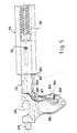
- the mechanism comprises means of manual operation, these means possibly being, for example, constituted by a pull tab 60 secured to the counter-rod 14 and affecting the advantageous shape of a handle allowing it to be easily taken by hand.
- the locking-unlocking means consist of a trigger 61 rotatably mounted in cooperation with the manual zipper 60.
- This trigger assumes the shape of an "L” and is mounted around an axis of rotation 64 located at the base of the pull tab 60, this base being the common part between the pull tab 60 and the counter rod 14.
- the axis of rotation is located at the common point of the two parts 62, 63 of the "L” and the trigger is arranged in cooperation with zipper 60 from so that the part 62 is placed in the hollow 68 of this pull tab and that the part 63 is in the extension of the rod 10 in its sliding direction.
- the end 67 of this part 63 must be able to abut, when it is in a certain position, as will be explained below, against the end 65 of the rod 60 facing the counter-rod 14.
- the trigger 61 is therefore able to take two positions respectively illustrated in FIG. 5 in broken lines and in solid lines, a first position in which the part 62 makes an angle of a certain value with the pull tab 60, and a second position in which this part 62 makes a substantially zero angle with the pull tab, so that, when the trigger is in the first position, the end 67 of its part 63 is able to oppose the respective sliding of the rod 10 and counter rod 14, and that, when it is in the second position, this part 63 is erased from the sliding path of the two rods and counter-rods relative to one another.
- the mechanism comprises elastic means 66, for example a spring, which tend to bring the trigger back to the first position, that shown in broken lines.
- the slide 1 is generally disposed folded in an enclosure 40 fixed to the door 3 of the aircraft 2. Straps 41 secure the slide with the attachment mechanism by going around, more particularly, the rod 10.
- the mechanism When the door is closed, FIG. 2, the mechanism is controlled to be in its "out” position with the end 13 in the housing 9 of the shoe 5 and the end piece 24 in the hollow housing 7, this control being carried out with the finger 27 , by the linkage.
- the key 30 blocks these two elements in this position.
- the finger 27 runs through the notch 26 until it is released by the outlet 28 to dissociate the slide from the door, the slide is then inflated and extends over the sea 50, FIG.
- the mechanism is easily dissociated from the two shoes.
- the personnel only have one manipulation to perform.
- grasping the pull tab 60 it also grips the trigger 61 to make it pass into the second angular position, that is to say that in which its part 62 makes with the pull tab a substantially zero angle, the part 63 disappears and allows the counter-rod 14 to slide relative to the rod 10, this part 63 entering, in this embodiment, into the cavity 16.
- the procedure consists of positioning it parallel to the waves, then opening the "passenger" doors on the side opposite to that from which the swell 70 comes (fig. 4), because it is preferable to do not open the doors on the side of this swell 70. To save all the passengers, it is then necessary to transport the slides 71 of these locked doors, on the thresholds of the open doors.
- the unclipping of the mechanism for hanging on a door threshold, and then hanging it on another presents no difficulty and can be done very quickly.
- the mechanism according to the invention therefore allows the transport of a slide and its attachment mechanism from one door to another and in the best conditions.
- this mechanism makes it possible to quickly disengage a slide from an aircraft when any need arises.
Landscapes
- Business, Economics & Management (AREA)
- Emergency Management (AREA)
- Engineering & Computer Science (AREA)
- Aviation & Aerospace Engineering (AREA)
- Lock And Its Accessories (AREA)
- Footwear And Its Accessory, Manufacturing Method And Apparatuses (AREA)
- Clamps And Clips (AREA)
- Holders For Apparel And Elements Relating To Apparel (AREA)
- Mechanical Control Devices (AREA)
- Air Bags (AREA)
Applications Claiming Priority (1)
| Application Number | Priority Date | Filing Date | Title |
|---|---|---|---|
| FR8711145A FR2619075B1 (fr) | 1987-08-05 | 1987-08-05 | Mecanisme d'accrochage d'un dispositif de sauvetage du type toboggan simple ou canot pour aeronef |
Publications (2)
| Publication Number | Publication Date |
|---|---|
| EP0363543A1 true EP0363543A1 (de) | 1990-04-18 |
| EP0363543B1 EP0363543B1 (de) | 1992-03-11 |
Family
ID=9353922
Family Applications (1)
| Application Number | Title | Priority Date | Filing Date |
|---|---|---|---|
| EP88402592A Expired - Lifetime EP0363543B1 (de) | 1987-08-05 | 1988-10-13 | Verankerungsmechanik einer Notausstiegsrutsche oder eines Rettungsbootes für Flugzeuge |
Country Status (5)
| Country | Link |
|---|---|
| US (1) | US4927098A (de) |
| EP (1) | EP0363543B1 (de) |
| DE (1) | DE3869132D1 (de) |
| ES (1) | ES2030192T3 (de) |
| FR (1) | FR2619075B1 (de) |
Families Citing this family (3)
| Publication number | Priority date | Publication date | Assignee | Title |
|---|---|---|---|---|
| DE102018130483B3 (de) * | 2018-08-31 | 2019-11-07 | Airbus Operations Gmbh | Passagiertüranordnung für ein Flugzeugsegment |
| US11292603B2 (en) | 2018-08-31 | 2022-04-05 | Airbus Operations Gmbh | Passenger door arrangement for an aircraft segment |
| DE102018121363B3 (de) | 2018-08-31 | 2019-09-05 | Airbus Operations Gmbh | Passagiertüranordnung für ein Flugzeugsegment |
Citations (4)
| Publication number | Priority date | Publication date | Assignee | Title |
|---|---|---|---|---|
| US3397432A (en) * | 1967-01-06 | 1968-08-20 | Mc Donnell Douglas Corp | Latch assembly |
| US3435492A (en) * | 1966-08-25 | 1969-04-01 | Mc Donnell Douglas Corp | Retaining latch |
| DE2029167A1 (de) * | 1970-06-12 | 1971-12-16 | Messerschmitt Bolkow Blohm GmbH, 8000 München | Verankerungsmechanik einer Notaus Stiegsrutsche fur Flugzeuge |
| EP0192503A1 (de) * | 1985-01-24 | 1986-08-27 | AEROSPATIALE Société Nationale Industrielle | Getriebe für automatische Betätigung einer Rettungsvorrichtung bei Öffnung einer Ausgangstür |
-
1987
- 1987-08-05 FR FR8711145A patent/FR2619075B1/fr not_active Expired
-
1988
- 1988-10-13 EP EP88402592A patent/EP0363543B1/de not_active Expired - Lifetime
- 1988-10-13 ES ES198888402592T patent/ES2030192T3/es not_active Expired - Lifetime
- 1988-10-13 DE DE8888402592T patent/DE3869132D1/de not_active Expired - Fee Related
- 1988-10-18 US US07/259,758 patent/US4927098A/en not_active Expired - Fee Related
Patent Citations (4)
| Publication number | Priority date | Publication date | Assignee | Title |
|---|---|---|---|---|
| US3435492A (en) * | 1966-08-25 | 1969-04-01 | Mc Donnell Douglas Corp | Retaining latch |
| US3397432A (en) * | 1967-01-06 | 1968-08-20 | Mc Donnell Douglas Corp | Latch assembly |
| DE2029167A1 (de) * | 1970-06-12 | 1971-12-16 | Messerschmitt Bolkow Blohm GmbH, 8000 München | Verankerungsmechanik einer Notaus Stiegsrutsche fur Flugzeuge |
| EP0192503A1 (de) * | 1985-01-24 | 1986-08-27 | AEROSPATIALE Société Nationale Industrielle | Getriebe für automatische Betätigung einer Rettungsvorrichtung bei Öffnung einer Ausgangstür |
Also Published As
| Publication number | Publication date |
|---|---|
| FR2619075A1 (fr) | 1989-02-10 |
| FR2619075B1 (fr) | 1989-12-15 |
| EP0363543B1 (de) | 1992-03-11 |
| DE3869132D1 (de) | 1992-04-16 |
| US4927098A (en) | 1990-05-22 |
| ES2030192T3 (es) | 1992-10-16 |
Similar Documents
| Publication | Publication Date | Title |
|---|---|---|
| EP0133082B1 (de) | Sicherheitseinrichtung zum Öffnen einer Flugzeugtür die sich im Fall von Überdruck innerhalb des Flugzeugs nach aussen öffnet und eine so ausgestattete Tür | |
| CA2918970C (fr) | Dispositif de manoeuvre d'au moins une trappe d'un aeronef comprenant une poignee de commande | |
| EP0061398B1 (de) | Verfahren und Vorrichtung zum Speichern und Ausklinken von zylindrischen Objekten in Fahrzeugen | |
| EP2181378B1 (de) | Triebwerksgondel zum einbau in ein flugzeug | |
| EP1644604A2 (de) | Zunge zum verbinden zweier verkleidungen einer flugzeugstruktur | |
| EP1142784B1 (de) | Flugzeugtür und damit ausgerüstetes Flugzeug | |
| CA2199495A1 (fr) | Remote manoeuvrable snap-hook to make a rope fast | |
| EP2431555B1 (de) | Verriegelungsvorrichtung für eine Aussenklappe | |
| EP0493998B1 (de) | Seilanlage auf einem Hubschrauber | |
| EP0363543B1 (de) | Verankerungsmechanik einer Notausstiegsrutsche oder eines Rettungsbootes für Flugzeuge | |
| EP0541422B1 (de) | Sicherheitsverriegelungsvorrichtung mit umkippbarem Zurückhaltehaken | |
| FR3110925A1 (fr) | Dispositif d’accès de secours d’ouvrant de véhicule à levier de rétention et fil de traction | |
| EP1404605A1 (de) | Verriegelungsvorrichtung für schachttür mit unabhängiger notentriegelungsvorrichtung | |
| FR2796251A1 (fr) | Casque modulaire a montage simplifie et resistant aux contraintes aerodynamiques | |
| FR3118941A1 (fr) | Procédé et ensemble de guidage stabilisateur de porte de véhicule à verrouillage de bielle. | |
| EP4480546A1 (de) | Seilblockiervorrichtung und verfahren zur verwendung | |
| FR2458459A1 (fr) | Dispositif d'accouplement mecanique et electrique pour charges, notamment militaires | |
| FR2708249A1 (fr) | Adaptateur pour sytèmes d'assistance à l'atterrissage et au décollage d'hélicoptères. | |
| EP1852309A1 (de) | Gepäckabdeckungsvorrichtung für Kraftfahrzeuge mit automatischer Teilöffnung und entsprechendes Kraftfahrzeug | |
| EP0354107B1 (de) | Befestigungsvorrichtung zum schnellen Andocken und Lösen einer Struktur | |
| EP3272638B1 (de) | Steuer- und kontollvorrichtung für segel eines segelschiffs oder lenkdrachen (kite) | |
| FR2460254A1 (fr) | Procede et appareil de declenchement de parachute pour avions de transport | |
| EP1151880A1 (de) | Umstellbare Tür für Motorfahrzeug | |
| EP3921230B1 (de) | Auswurfsystem für einen notausstieg eines fahrzeugs | |
| FR3073818A1 (fr) | Element de separation pour cabine de plateforme, plateforme comprenant un tel element et procede d'utilisation d'un tel element |
Legal Events
| Date | Code | Title | Description |
|---|---|---|---|
| PUAI | Public reference made under article 153(3) epc to a published international application that has entered the european phase |
Free format text: ORIGINAL CODE: 0009012 |
|
| AK | Designated contracting states |
Kind code of ref document: A1 Designated state(s): DE ES GB IT NL |
|
| 17P | Request for examination filed |
Effective date: 19900504 |
|
| 17Q | First examination report despatched |
Effective date: 19910514 |
|
| GRAA | (expected) grant |
Free format text: ORIGINAL CODE: 0009210 |
|
| AK | Designated contracting states |
Kind code of ref document: B1 Designated state(s): DE ES GB IT NL |
|
| GBT | Gb: translation of ep patent filed (gb section 77(6)(a)/1977) | ||
| REF | Corresponds to: |
Ref document number: 3869132 Country of ref document: DE Date of ref document: 19920416 |
|
| ITF | It: translation for a ep patent filed | ||
| PGFP | Annual fee paid to national office [announced via postgrant information from national office to epo] |
Ref country code: ES Payment date: 19921005 Year of fee payment: 5 |
|
| PGFP | Annual fee paid to national office [announced via postgrant information from national office to epo] |
Ref country code: GB Payment date: 19921006 Year of fee payment: 5 |
|
| REG | Reference to a national code |
Ref country code: ES Ref legal event code: FG2A Ref document number: 2030192 Country of ref document: ES Kind code of ref document: T3 |
|
| PGFP | Annual fee paid to national office [announced via postgrant information from national office to epo] |
Ref country code: DE Payment date: 19921022 Year of fee payment: 5 |
|
| PGFP | Annual fee paid to national office [announced via postgrant information from national office to epo] |
Ref country code: NL Payment date: 19921031 Year of fee payment: 5 |
|
| PLBE | No opposition filed within time limit |
Free format text: ORIGINAL CODE: 0009261 |
|
| STAA | Information on the status of an ep patent application or granted ep patent |
Free format text: STATUS: NO OPPOSITION FILED WITHIN TIME LIMIT |
|
| 26N | No opposition filed | ||
| PG25 | Lapsed in a contracting state [announced via postgrant information from national office to epo] |
Ref country code: GB Effective date: 19931013 |
|
| PG25 | Lapsed in a contracting state [announced via postgrant information from national office to epo] |
Ref country code: ES Free format text: LAPSE BECAUSE OF THE APPLICANT RENOUNCES Effective date: 19931014 |
|
| PG25 | Lapsed in a contracting state [announced via postgrant information from national office to epo] |
Ref country code: NL Effective date: 19940501 |
|
| GBPC | Gb: european patent ceased through non-payment of renewal fee |
Effective date: 19931013 |
|
| NLV4 | Nl: lapsed or anulled due to non-payment of the annual fee | ||
| PG25 | Lapsed in a contracting state [announced via postgrant information from national office to epo] |
Ref country code: DE Effective date: 19940701 |
|
| REG | Reference to a national code |
Ref country code: ES Ref legal event code: FD2A Effective date: 19991007 |
|
| PG25 | Lapsed in a contracting state [announced via postgrant information from national office to epo] |
Ref country code: IT Free format text: LAPSE BECAUSE OF NON-PAYMENT OF DUE FEES;WARNING: LAPSES OF ITALIAN PATENTS WITH EFFECTIVE DATE BEFORE 2007 MAY HAVE OCCURRED AT ANY TIME BEFORE 2007. THE CORRECT EFFECTIVE DATE MAY BE DIFFERENT FROM THE ONE RECORDED. Effective date: 20051013 |