EP0363555A2 - Bett-Bediengerät - Google Patents
Bett-Bediengerät Download PDFInfo
- Publication number
- EP0363555A2 EP0363555A2 EP89105329A EP89105329A EP0363555A2 EP 0363555 A2 EP0363555 A2 EP 0363555A2 EP 89105329 A EP89105329 A EP 89105329A EP 89105329 A EP89105329 A EP 89105329A EP 0363555 A2 EP0363555 A2 EP 0363555A2
- Authority
- EP
- European Patent Office
- Prior art keywords
- bed control
- control device
- control unit
- bed
- call
- Prior art date
- Legal status (The legal status is an assumption and is not a legal conclusion. Google has not performed a legal analysis and makes no representation as to the accuracy of the status listed.)
- Granted
Links
Images
Classifications
-
- G—PHYSICS
- G08—SIGNALLING
- G08B—SIGNALLING SYSTEMS, e.g. PERSONAL CALLING SYSTEMS; ORDER TELEGRAPHS; ALARM SYSTEMS
- G08B3/00—Audible signalling systems, e.g. audible personal calling systems
- G08B3/10—Audible signalling systems, e.g. audible personal calling systems using electric transmission; using electromagnetic transmission
- G08B3/1008—Personal calling arrangements or devices, i.e. paging systems
Definitions
- the invention relates to a bed control unit for call and intercom systems in hospitals and nursing homes, with a device for adjusting the volume of an acoustic transducer, wherein a sound line selector switch is provided, through which a plurality of sound lines can be connected to a headphone.
- bed control units with a call button, reassurance lamp, buttons for switching on the room lighting via remote switches and acoustic transducers for voice communication with the sister are to be provided for such call and intercom systems .
- bed control units that enable two-way or two-way communication.
- headphones can also be connected to the bed control unit in order to be able to receive several programs by selection via a program selector switch.
- the object of the invention is to improve the manageability of the known bed control device.
- the bed control device is attached to a pivotable bracket or to a stand.
- the bed control unit can be easily brought into a user-friendly position by the patient. The same applies if the bed control unit is attached to a stand that is close to the bed.
- a further development of the invention is that a holder is provided for a telephone set connected to the bed control unit in the form of a handset with a built-in dialing keypad.
- the ease of use is increased, since the telephone set can be used not only for conventional telephone connections but also for other functions.
- the call button is attached to the telephone and a voice connection can be established with the sister on the telephone because of the nurse call.
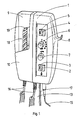
- the bed control unit 1 has a holder 10 for the telephone set 9 provided with a selection keypad 18, which is designed as a handset and is connected to the bed control unit 1 via the connecting cord 16. Furthermore, a headphone (not shown) is connected to the bed control device 1 via the cable 15, which can be hooked onto the hook 8 attached to the housing of the bed control device 1. (Fig. 1)
- the bed control unit 1 also contains a call button 2 for emergency calls, a reassurance lamp 3 to indicate that the emergency call has been acknowledged, a button 4 for switching on a light source, an orientation light 5, which enables the bed control device 1 to be found in the dark, one Sound line selector switch 6 and a volume control 7.
- the attachment 13 is attached to the lower part of the bed operating device 1, and the connecting cable 17 is also connected to the underside.
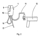
- Fig. 2 an embodiment of the bracket of the bed control device 1 is shown. This is attached to the end of a pivotable bracket 11 which is attached, for example, to a table 12 or to the wall of the room.
- Another possibility is to mount the bed control unit 1 at the end of a stand (not shown) standing on the floor.
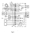
- the block diagram according to FIG. 3 shows the circuit diagram of the bed control device B, which is identical to the bed control device 1 according to FIG. 1 or 2.
- the bed control unit B is connected to a large number of devices via the common connecting cable AK and a common plug.
- the audio lines TL1 to TLn are provided, which are connected to the audio line selection switch TW via the connection points K11 to K32.
- the volume control is used to adjust the volume.
- the headphone KH is connected to the sound line selector switch TW and the volume control LR via the connection points K1 and K2.
- the sound line selector switch TW has yet another position via which the sound of a television set up in the patient's room can be received.
- the connection points K41 and K42 are connected to a room-specific remote control device ST which has switching means S which are individual for the bed operating device.
- the bed control unit B also has a light button LT, which is connected via the connection points LT1 and LT2 to a switching means S which enables the control of the switching on and off of a light source in the patient's room with the aid of a low voltage.
- the switching means S works in conjunction with a power supply unit N, which is connected to the light network NL and generates the low voltage for the light button LT and for an orientation lamp 0L, which can also be designed as a light-emitting diode and possibly depending on the time of day or depending of the switching state of the light source L only lights up in the dark and makes it easier for the patient to find the bed control unit B.
- a call button RT1 is provided in the bed control unit B, which is connected to a nurse call system SR via the connection points RTI to RT3.
- a further call button RT2 is provided in the telephone set FA, which connects the call key RT1 in parallel and also enables the call to be sent via the telephone set FA.
- a reassurance lamp BL which can also be designed as a light-emitting diode, serves as the acknowledgment signal, which indicates to the patient that his call has been acknowledged.
Landscapes
- Physics & Mathematics (AREA)
- Electromagnetism (AREA)
- General Physics & Mathematics (AREA)
- Accommodation For Nursing Or Treatment Tables (AREA)
- Invalid Beds And Related Equipment (AREA)
- Harvester Elements (AREA)
- Mattresses And Other Support Structures For Chairs And Beds (AREA)
- Interconnected Communication Systems, Intercoms, And Interphones (AREA)
Abstract
Description
- Die Erfindung betrifft ein Bett-Bediengerät für Ruf- und Sprechanlagen in Krankenhäusern und Pflegeheimen, mit einer Einrichtung zur Lautstärkeeinstellung eines akustischen Wandlers, wobei ein Tonleitungswahlschalter vorgesehen ist, durch weichen eine Vielzahl von Tonleitungen mit einem Kopfhörer verbindbar sind.
- Es ist bereits bekannt, in Ruf- und Sprechanlagen für Krankenhäuser und Pflegeheime ein bewegliches Bett-Bediengerät einzusetzen, welches vom Patienten in die Hand genommen werden kann. Nach der Vorschrift DIN 41050, Teil, 1, Seite 3, Abs. 6.3, sind für derartige Ruf- und Sprechanlagen Bett-Bediengerate mit einer Ruftaste, Beruhigungslampe, Tasten zur Einschaltung der Raumbeleuchtung über Fernschalter und akustische Wandler für den Sprechverkehr mit der Schwester vorzusehen. Darüberhinaus gibt es auch Bett-Bediengeräte, welche ein Wechsel- oder Gegensprechen ermöglichen. Weiterhin kann an dem Bett-Bediengerät auch ein Kopfhörer angeschlossen werden, um mehrere Programme durch Auswahl über einen Programmwahlschalter empfangen zu können.
- Weiterhin ist aus der DE-PS 32 40 145 ein Bett-Bediengerät bekannt, welches bei Nichtbenutzung in eine Wandhalterung eingesetzt werden kann.
- Die Aufgabe der Erfindung besteht darin, die Handhabbarkeit des bekannten Bett-Bediengeräts zu verbessern.
- Diese Aufgabe wird dadurch gelöst, daß das Bett-Bediengerät an einem schwenkbaren Bügel oder an einem Ständer befestigt ist.
- Durch den beispielsweise an einer Wand oder an einem Tisch angebrachten schwenkbaren Bügel kann das Bett-Bediengerät leicht vom Patienten in eine bedienungsgerechte Lage gebracht werden. Das gleiche gilt, wenn das Bett-Bediengerät an einem Ständer befestigt ist, welcher in der Nähe des Betts steht.
- Eine Weiterbildung der Erfindung besteht darin, daß eine Halterung für einen an dem Bett-Bediengerät angeschlossenen Fernsprechapparat in Form eines Handapparates mit eingebauter Wähltastatur vorgesehen ist.
- Durch die Bereitstellung eines Fernsprechapparates wird der Bedienungskomfort erhöht, da der Fernsprechapparat nicht nur für herkömmliche Fernsprechverbindungen sondern auch für weitere Funktionen herangezogen werden kann, so z. B. für den Schwesternruf, wobei die Ruftaste am Fernsprechapparat angebracht ist und über den Fernsprechapparat aufgrund des Schwesternrufs eine Sprechverbindung mit der Schwester herstellbar ist.
- Weitere Vorteile ergeben sich aus den Unteransprüchen.
- Die Erfindung wird anhand eines Ausführungsbeispiels näher erläutert, welches in der Zeichnung dargestellt ist. Es zeigt:
- Fig. 1 die perspektivische Ansicht des Bett-Bediengeräts,
- Fig. 2 die Befestigung des Bett- Bediengeräts und
- Fig. 3 die Schaltungsanordnung des Bett-Bediengeräts.
- Das Bett-Bediengerät 1 weist eine Halterung 10 für den mit einer Wahltastatur 18 versehenen Fernsprechapparat 9 auf, welcher als Handapparat ausgebildet ist und über die Anschlußschnur 16 mit dem Bett-Bediengerät 1 verbunden ist. Weiterhin ist an dem Bett-Bediengerät 1 ein nicht gezeigter Kopfhörer über das Kabel 15 angeschlossen, welcher am Gehäuse des Bett-Bediengeräts 1 angebrachten Haken 8 einhängbar ist. (Fig. 1)
- Das Bett-Bediengerät 1 enthält außerdem eine Ruftaste 2 für Notruf, eine Beruhigungslampe 3 zur Kennzeichnung, daß der Notruf quittiert wurde, eine Taste 4 zum Einschalten einer Lichtquelle, ein Orientierungslicht 5, welches das Auffinden des Bett-Bediengeräts 1 im Dunkeln ermöglicht, einen Tonleitungswahlschalter 6 und einen Lautstärkeregler 7. Am Unterteil des Bett-Bediengeräts 1 ist die Befestigung 13 angebracht, außerdem ist an der Unterseite das Anschlußkabel 17 angeschlossen.
- In Fig. 2 wird ein Ausführungsbeispiel der Halterung des Bett-Bediengeräts 1 gezeigt. Dieses ist am Ende eines schwenkbaren Bügels 11 befestigt, welcher beispielsweise mit einem Tisch 12 oder auch mit der Wand des Raumes befestigt ist.
- Eine andere Möglichkeit besteht darin, daß Bett-Bediengerät 1 am Ende eines auf dem Fußboden stehenden nicht gezeigten Ständers anzubringen.
- Das Blockschaltbild gemäß Fig. 3 zeigt das Schaltbild des Bett-Bediengeräts B, welches mit dem Bett-Bediengerät 1 gemäß Fig. 1 oder 2 identisch ist. Über das gemeinsame Anschlußkabel AK und einen gemeinsamen Stecker ist das Bett-Bediengerät B mit einer Vielzahl von Einrichtungen verbunden.
- Zur Übertragung von Rundfunk- und Musikprogrammen sind die Tonleitungen TL1 bis TLn vorgesehen, welche über die Anschlußpunkte K11 bis K32 mit dem Tonleitungswahlschalter TW verbunden sind. Zur Ein stellung der Lautstärke dient der Lautstärkeregler LR. Am Tonleitungswahlschalter TW und über den Lautstärkeregler LR ist der Kopfhörer KH über die Anschlußpunkte K1 und K2 angschlossen. Der Tonleitungswahlschalter TW weist noch eine weitere Position auf, über welche der Ton eines im Patientenzimmer aufgestellten Fernsehgeräts empfangen werden kann. Zu diesem Zweck sind die Anschlußpunkte K41 und K42 mit einer raumindividuellen Fernsteuereinrichtung ST verbunden, welche bett-bediengeräte-individuelle Schaltmittel S aufweist. Diese verbinden den Kopfhörerausgang KA des Fernsehgeräts FS mit einem der Ausgänge B1 bis B3, und zwar auf Veranlassung einer zentralen Erfassungs- und Verarbeitungseinrichtung EST, welche über eine Datenleitung DL mit einer Vielzahl von Fernsteuereinrichtungen ST verbunden ist. Der Patient ist in der Lage, über den durchgeschleiften Leitungen der Anschlußpunkte a, b und E mit einer Fernsprechvermittlungsanlage FV verbundenen Fernsprechapparat FA, und zwar nach Herstellung einer Verbindung von demselben zu der an der Fernsprechvermittlungsanlage VF angeschlossenen zentralen Erfassungs- und Verarbeitungseinrichtung EST dieselbe zur Aussendung entsprechender Steuerbefehle zu veranlassen, welche die Ein- und Ausschaltung des Fernsehgeräts FS, die Kanalauswahl und die Durchschaltung des Fernsehtons in der bereits beschriebenen Weise veranlassen.
- Das Bett-Bediengerät B weist weiterhin eine Lichttaste LT auf, welche über die Anschlußpunkte LT1 und LT2 mit einem Schaltmittel S verbunden ist, welchesdie Steuerung des Ein- und Ausschaltens einer Lichtquelle im Patientenzimmer mit Hilfe einer niedrigen Spannung ermöglicht. Das Schaltmittel S arbeitet in Verbindung mit einem Netzgerät N, welches am Lichtnetz NL angeschlossen ist und die niedrige Spannung für die Lichttaste LT und für eine Orientierungslampe 0L erzeugt, die auch als Leuchtdiode ausgebildet sein kann und evtl. abhängig von der Tageszeit bzw. in Abhängigkeit von dem Schaltzustand der Lichtquelle L nur bei Dunkelheit leuchtet und dem Patienten das Auffinden des Bett-Bediengeräts B erleichtert.
- Für den Schwesternruf ist im Bett-Bediengerät B eine Ruftaste RT1 vorgesehen, welche über die Anschlußpunkte RTI bis RT3 mit einer Schwesternrufanlage SR verbunden ist. Parallel zur Ruftaste RT1 ist im Fernsprechapparat FA eine weitere Ruftaste RT2 vorgesehen, welche der Ruftaste RT1 parallel geschaltet und die Rufaussendung auch über den Fernsprechapparat FA ermöglicht. Als Quittungssignal, welches den Patienten darauf hinweist, daß sein Ruf zur Kenntnis genommen worden ist, dient eine Beruhigungslampe BL, welche ebenfalls als Leuchtdiode ausgebildet sein kann.
Claims (7)
dadurch gekennzeichnet,
daß das Bett-Bediengerät (1, B) an einem schwenkbaren Bügel (11) oder an einem Ständer befestigt ist.
dadurch gekennzeichnet,
daß eine Halterung (10) für einen an dem Bett-Bediengerät (1, B) angeschlossene Fernsprechapparat (9, FA) in Form eines Handapparates mit eingebauten Wähltastatur (18) vorgesehen ist.
dadurch gekennzeichnet,
daß über den Tonleitungswahlschalter (6, TW) der Kopfhörer (KH) mit einer Fernsteuereinrichtung (ST) verbindbar ist, welche den Kopfhörerausgang eines im Raum des Bett-Bediengeräts befindlichen Fernsehräts(FS) zu dem betreffenden Bett-Bediengerät (1,B) aufgrund von Steuerbefehlen durchschaltet, welche über die Wähltastatur (18) im Rahmen einer Fernsprechverbindung in der Fernsteuereinrichtung (ST) auslösbar sind.
dadurch gekennzeichnet,
daß am Gehäuse desselben ein Haken (8) zum Aufhängen des Kopfhörers (KH) angebracht ist.
dadurch gekennzeichnet,
daß eine Ruftaste (2, RT1) vorgesehen ist, welche mit einer Schwesternrufanlage (SR) verbunden ist und daß parallel zur Ruftaste (2, RT1) eine weitere Ruftaste (RT2) geschaltet ist, welche am Fernsprechapparat (FA) angebracht ist.
dadurch gekennzeichnet,
daß eine Orientierungslampe (5, 0L) vorgesehen ist.
dadurch gekennzeichnet,
daß sämtliche Leitungen mit Ausnahme der Anschlüsse des Fernsprechapparates (9, FA) und des Kopfhörers (KH) über eine gemeinsames Anschlußkabel (AK) geführt sind.
Priority Applications (1)
| Application Number | Priority Date | Filing Date | Title |
|---|---|---|---|
| AT89105329T ATE89995T1 (de) | 1988-07-30 | 1989-03-25 | Bett-bediengeraet. |
Applications Claiming Priority (2)
| Application Number | Priority Date | Filing Date | Title |
|---|---|---|---|
| DE3826083A DE3826083A1 (de) | 1988-07-30 | 1988-07-30 | Bett-bediengeraet |
| DE3826083 | 1988-07-30 |
Publications (3)
| Publication Number | Publication Date |
|---|---|
| EP0363555A2 true EP0363555A2 (de) | 1990-04-18 |
| EP0363555A3 EP0363555A3 (en) | 1990-06-20 |
| EP0363555B1 EP0363555B1 (de) | 1993-06-02 |
Family
ID=6360005
Family Applications (1)
| Application Number | Title | Priority Date | Filing Date |
|---|---|---|---|
| EP89105329A Expired - Lifetime EP0363555B1 (de) | 1988-07-30 | 1989-03-25 | Bett-Bediengerät |
Country Status (3)
| Country | Link |
|---|---|
| EP (1) | EP0363555B1 (de) |
| AT (1) | ATE89995T1 (de) |
| DE (2) | DE3826083A1 (de) |
Cited By (7)
| Publication number | Priority date | Publication date | Assignee | Title |
|---|---|---|---|---|
| AT99U1 (de) * | 1993-06-18 | 1995-02-27 | Thiede Gerhard | Nachttisch |
| AT98U1 (de) * | 1993-06-18 | 1995-02-27 | Thiede Gerhard Thiede Gerhard | Nachttisch |
| WO1997039946A1 (en) * | 1996-04-25 | 1997-10-30 | Sony Trans Com, Inc. | An integrated electronic system utilizing a universal interface to support telephony and other communication services |
| WO2000072344A1 (de) * | 1999-05-21 | 2000-11-30 | Albert Ackermann Gmbh + Co. Kg | Bett-bediengerät für den pflegebereich |
| US6481688B1 (en) | 1992-11-30 | 2002-11-19 | Hill-Rom Services, Inc. | Hospital bed communication and control device |
| US6486792B1 (en) | 1998-04-14 | 2002-11-26 | Hill-Rom Services, Inc. | Communication and bed function control apparatus |
| US10363182B2 (en) | 2014-07-14 | 2019-07-30 | Hill-Rom Services, Inc. | Patient control arm with phone dock and head of bed lockout |
Families Citing this family (5)
| Publication number | Priority date | Publication date | Assignee | Title |
|---|---|---|---|---|
| DE4108160C1 (de) * | 1991-03-14 | 1992-10-08 | Albert Ackermann Gmbh & Co Kg, 5270 Gummersbach, De | |
| EP0542048A1 (de) * | 1991-11-13 | 1993-05-19 | Robert Bosch Gmbh | Bett-Bediengerät mit zusätzlichen Funktionen |
| DE4243504A1 (de) * | 1992-12-22 | 1994-06-23 | Skt Schmelter Gmbh & Co Kg | Verfahren und Anordnung zur Steuerung von Kommunikationsendgeräten |
| DE9405518U1 (de) * | 1994-03-31 | 1995-05-04 | Siemens Ag | Multimediale Kommunikationseinrichtung |
| DE10141574A1 (de) * | 2001-08-24 | 2003-03-13 | Barbara Doering | Trinkvorrichtung für bettlägerige Kranke |
Family Cites Families (6)
| Publication number | Priority date | Publication date | Assignee | Title |
|---|---|---|---|---|
| US3112968A (en) * | 1961-06-01 | 1963-12-03 | Beryl W Cotton | Nurse call and utility unit |
| DE1441403B1 (de) * | 1963-01-04 | 1970-06-04 | Bohne Dipl Ing Alfred | Elektrisches Schalt- und Signalgeraet fuer Krankenbetten |
| DE1905098A1 (de) * | 1969-02-01 | 1970-08-13 | Bayer Ag | Verfahren zur Herstellung von Polyamiden |
| US3757363A (en) * | 1970-09-10 | 1973-09-11 | J Langlais | Patient communicator support |
| DE8230430U1 (de) * | 1982-10-29 | 1988-02-11 | Alois Zettler Elektrotechnische Fabrik GmbH, 8000 München | Bett-Bediengerät |
| DE3240145C2 (de) * | 1982-10-29 | 1987-04-16 | Alois Zettler Elektrotechnische Fabrik GmbH, 8000 München | Bett-Bediengerät |
-
1988
- 1988-07-30 DE DE3826083A patent/DE3826083A1/de active Granted
-
1989
- 1989-03-25 DE DE8989105329T patent/DE58904562D1/de not_active Expired - Fee Related
- 1989-03-25 EP EP89105329A patent/EP0363555B1/de not_active Expired - Lifetime
- 1989-03-25 AT AT89105329T patent/ATE89995T1/de not_active IP Right Cessation
Cited By (10)
| Publication number | Priority date | Publication date | Assignee | Title |
|---|---|---|---|---|
| US6481688B1 (en) | 1992-11-30 | 2002-11-19 | Hill-Rom Services, Inc. | Hospital bed communication and control device |
| AT99U1 (de) * | 1993-06-18 | 1995-02-27 | Thiede Gerhard | Nachttisch |
| AT98U1 (de) * | 1993-06-18 | 1995-02-27 | Thiede Gerhard Thiede Gerhard | Nachttisch |
| WO1997039946A1 (en) * | 1996-04-25 | 1997-10-30 | Sony Trans Com, Inc. | An integrated electronic system utilizing a universal interface to support telephony and other communication services |
| US5835127A (en) * | 1996-04-25 | 1998-11-10 | Sony Corporation | Integrated electronic system utilizing a universal interface to support telephony and other communication services |
| US6486792B1 (en) | 1998-04-14 | 2002-11-26 | Hill-Rom Services, Inc. | Communication and bed function control apparatus |
| US6781517B2 (en) | 1998-04-14 | 2004-08-24 | Hill-Rom Services, Inc. | Communication and bed function control apparatus |
| WO2000072344A1 (de) * | 1999-05-21 | 2000-11-30 | Albert Ackermann Gmbh + Co. Kg | Bett-bediengerät für den pflegebereich |
| US10363182B2 (en) | 2014-07-14 | 2019-07-30 | Hill-Rom Services, Inc. | Patient control arm with phone dock and head of bed lockout |
| US11571347B2 (en) | 2014-07-14 | 2023-02-07 | Hill-Rom Services, Inc. | Patient control arm with phone dock and head-of-bed lockout |
Also Published As
| Publication number | Publication date |
|---|---|
| ATE89995T1 (de) | 1993-06-15 |
| EP0363555B1 (de) | 1993-06-02 |
| DE3826083A1 (de) | 1990-02-01 |
| DE3826083C2 (de) | 1990-07-26 |
| EP0363555A3 (en) | 1990-06-20 |
| DE58904562D1 (de) | 1993-07-08 |
Similar Documents
| Publication | Publication Date | Title |
|---|---|---|
| DE69518111T2 (de) | Anordnung zur Überprüfung eines Alarms | |
| DE69723588T2 (de) | Krankenschwester/Kranken-Kommunikationsverfahren | |
| DE2623573C3 (de) | Bildtelefon-Konferenzanlage | |
| EP0363555B1 (de) | Bett-Bediengerät | |
| EP0418831A2 (de) | Verfahren zur Personensuche in einer Fernsprechnebenstellenvermittlungsanlage mit Hilfe einer Personensucheinrichtung, die zur Personensuche sich voneinander unterscheidende Betriebsarten bereitstellt | |
| DE1270120B (de) | Telephonapparat in Form eines Fuß Standers mit einer Schaltvorrichtung in der Standflache | |
| DE102008052491B4 (de) | Deckenarmsystem | |
| DE3023988A1 (de) | Gegensprechanlage | |
| DE2523864A1 (de) | Mikrofon-lautsprecherkombination fuer kommunikationssysteme | |
| EP0749654B1 (de) | Kompakt-fernsprechendgerät | |
| DE66870C (de) | Schaltung zur Verbindung von Fernsprechstellen ohne Vermittelungsamt | |
| DE104080C (de) | ||
| DE102006000761B4 (de) | Türsprechanlage mit einer Busleitung | |
| DE4302164A1 (de) | Signalvorrichtung mit elektrischen Hauptadern zum Verbinden eines Signalgebers mit einem Auslöser | |
| DE9414245U1 (de) | Elektronischer Zweitwecker für Fernsprechendgeräte | |
| EP1122935A2 (de) | Computergesteuerte Nebenstellenanalage | |
| EP0191492A2 (de) | Rechnergesteuerte elektroakustische Diskussionsanlage | |
| DE1132979B (de) | Lichtruf- und Sprechanlage fuer Krankenhaeuser | |
| DE19917460A1 (de) | Türsprechanlage mit Türstation, mehreren Wohnungsstationen und einer Notrufeinrichtung | |
| DE3530261C2 (de) | ||
| DE1934020U (de) | Ueberwachungsgeraet mit mikrofon, sprechtasten und signallampen. | |
| DE2733693A1 (de) | Schaltungsanordnung fuer eine ruf-, tuerwechselsprech- und tueroeffneranlage | |
| DE4121195A1 (de) | Fernsprechanlage | |
| DE1190044B (de) | Einrichtung zur Schallaufnahme | |
| DE9007635U1 (de) | Fernsprechapparat mit einer Lauthöreinrichtung |
Legal Events
| Date | Code | Title | Description |
|---|---|---|---|
| PUAI | Public reference made under article 153(3) epc to a published international application that has entered the european phase |
Free format text: ORIGINAL CODE: 0009012 |
|
| AK | Designated contracting states |
Kind code of ref document: A2 Designated state(s): AT BE CH DE FR GB IT LI LU NL |
|
| PUAL | Search report despatched |
Free format text: ORIGINAL CODE: 0009013 |
|
| AK | Designated contracting states |
Kind code of ref document: A3 Designated state(s): AT BE CH DE FR GB IT LI LU NL |
|
| 17P | Request for examination filed |
Effective date: 19900517 |
|
| RAP1 | Party data changed (applicant data changed or rights of an application transferred) |
Owner name: TELENORMA GMBH |
|
| 17Q | First examination report despatched |
Effective date: 19910806 |
|
| GRAA | (expected) grant |
Free format text: ORIGINAL CODE: 0009210 |
|
| AK | Designated contracting states |
Kind code of ref document: B1 Designated state(s): AT BE CH DE FR GB IT LI LU NL |
|
| REF | Corresponds to: |
Ref document number: 89995 Country of ref document: AT Date of ref document: 19930615 Kind code of ref document: T |
|
| REF | Corresponds to: |
Ref document number: 58904562 Country of ref document: DE Date of ref document: 19930708 |
|
| ITF | It: translation for a ep patent filed | ||
| ET | Fr: translation filed | ||
| GBT | Gb: translation of ep patent filed (gb section 77(6)(a)/1977) |
Effective date: 19930906 |
|
| PLBE | No opposition filed within time limit |
Free format text: ORIGINAL CODE: 0009261 |
|
| STAA | Information on the status of an ep patent application or granted ep patent |
Free format text: STATUS: NO OPPOSITION FILED WITHIN TIME LIMIT |
|
| EPTA | Lu: last paid annual fee | ||
| 26N | No opposition filed | ||
| PGFP | Annual fee paid to national office [announced via postgrant information from national office to epo] |
Ref country code: LU Payment date: 19960301 Year of fee payment: 8 |
|
| PGFP | Annual fee paid to national office [announced via postgrant information from national office to epo] |
Ref country code: GB Payment date: 19960315 Year of fee payment: 8 |
|
| PGFP | Annual fee paid to national office [announced via postgrant information from national office to epo] |
Ref country code: BE Payment date: 19960321 Year of fee payment: 8 |
|
| PGFP | Annual fee paid to national office [announced via postgrant information from national office to epo] |
Ref country code: NL Payment date: 19960331 Year of fee payment: 8 |
|
| PG25 | Lapsed in a contracting state [announced via postgrant information from national office to epo] |
Ref country code: LU Free format text: LAPSE BECAUSE OF NON-PAYMENT OF DUE FEES Effective date: 19970325 Ref country code: GB Effective date: 19970325 |
|
| PG25 | Lapsed in a contracting state [announced via postgrant information from national office to epo] |
Ref country code: BE Effective date: 19970331 |
|
| BERE | Be: lapsed |
Owner name: TELENORMA G.M.B.H. Effective date: 19970331 |
|
| PG25 | Lapsed in a contracting state [announced via postgrant information from national office to epo] |
Ref country code: NL Effective date: 19971001 |
|
| GBPC | Gb: european patent ceased through non-payment of renewal fee |
Effective date: 19970325 |
|
| NLV4 | Nl: lapsed or anulled due to non-payment of the annual fee |
Effective date: 19971001 |
|
| PGFP | Annual fee paid to national office [announced via postgrant information from national office to epo] |
Ref country code: DE Payment date: 20010125 Year of fee payment: 13 |
|
| PGFP | Annual fee paid to national office [announced via postgrant information from national office to epo] |
Ref country code: FR Payment date: 20020320 Year of fee payment: 14 |
|
| PGFP | Annual fee paid to national office [announced via postgrant information from national office to epo] |
Ref country code: CH Payment date: 20020325 Year of fee payment: 14 Ref country code: AT Payment date: 20020325 Year of fee payment: 14 |
|
| PG25 | Lapsed in a contracting state [announced via postgrant information from national office to epo] |
Ref country code: DE Free format text: LAPSE BECAUSE OF NON-PAYMENT OF DUE FEES Effective date: 20021001 |
|
| PG25 | Lapsed in a contracting state [announced via postgrant information from national office to epo] |
Ref country code: AT Free format text: LAPSE BECAUSE OF NON-PAYMENT OF DUE FEES Effective date: 20030325 |
|
| PG25 | Lapsed in a contracting state [announced via postgrant information from national office to epo] |
Ref country code: LI Free format text: LAPSE BECAUSE OF NON-PAYMENT OF DUE FEES Effective date: 20030331 Ref country code: CH Free format text: LAPSE BECAUSE OF NON-PAYMENT OF DUE FEES Effective date: 20030331 |
|
| REG | Reference to a national code |
Ref country code: CH Ref legal event code: PL |
|
| PG25 | Lapsed in a contracting state [announced via postgrant information from national office to epo] |
Ref country code: FR Free format text: LAPSE BECAUSE OF NON-PAYMENT OF DUE FEES Effective date: 20031127 |
|
| REG | Reference to a national code |
Ref country code: FR Ref legal event code: ST |
|
| PG25 | Lapsed in a contracting state [announced via postgrant information from national office to epo] |
Ref country code: IT Free format text: LAPSE BECAUSE OF NON-PAYMENT OF DUE FEES;WARNING: LAPSES OF ITALIAN PATENTS WITH EFFECTIVE DATE BEFORE 2007 MAY HAVE OCCURRED AT ANY TIME BEFORE 2007. THE CORRECT EFFECTIVE DATE MAY BE DIFFERENT FROM THE ONE RECORDED. Effective date: 20050325 |