EP0363600B1 - Dispositif de décalage angulaire d'un arbre à cames - Google Patents
Dispositif de décalage angulaire d'un arbre à cames Download PDFInfo
- Publication number
- EP0363600B1 EP0363600B1 EP19890114778 EP89114778A EP0363600B1 EP 0363600 B1 EP0363600 B1 EP 0363600B1 EP 19890114778 EP19890114778 EP 19890114778 EP 89114778 A EP89114778 A EP 89114778A EP 0363600 B1 EP0363600 B1 EP 0363600B1
- Authority
- EP
- European Patent Office
- Prior art keywords
- shaft
- camshaft
- clutch
- shoulder
- drive gear
- Prior art date
- Legal status (The legal status is an assumption and is not a legal conclusion. Google has not performed a legal analysis and makes no representation as to the accuracy of the status listed.)
- Expired - Lifetime
Links
- 230000005540 biological transmission Effects 0.000 claims 2
- 235000014443 Pyrus communis Nutrition 0.000 claims 1
- 238000002485 combustion reaction Methods 0.000 claims 1
- 239000007788 liquid Substances 0.000 claims 1
Images

Classifications
-
- F—MECHANICAL ENGINEERING; LIGHTING; HEATING; WEAPONS; BLASTING
- F01—MACHINES OR ENGINES IN GENERAL; ENGINE PLANTS IN GENERAL; STEAM ENGINES
- F01L—CYCLICALLY OPERATING VALVES FOR MACHINES OR ENGINES
- F01L1/00—Valve-gear or valve arrangements, e.g. lift-valve gear
- F01L1/34—Valve-gear or valve arrangements, e.g. lift-valve gear characterised by the provision of means for changing the timing of the valves without changing the duration of opening and without affecting the magnitude of the valve lift
- F01L1/344—Valve-gear or valve arrangements, e.g. lift-valve gear characterised by the provision of means for changing the timing of the valves without changing the duration of opening and without affecting the magnitude of the valve lift changing the angular relationship between crankshaft and camshaft, e.g. using helicoidal gear
-
- F—MECHANICAL ENGINEERING; LIGHTING; HEATING; WEAPONS; BLASTING
- F16—ENGINEERING ELEMENTS AND UNITS; GENERAL MEASURES FOR PRODUCING AND MAINTAINING EFFECTIVE FUNCTIONING OF MACHINES OR INSTALLATIONS; THERMAL INSULATION IN GENERAL
- F16D—COUPLINGS FOR TRANSMITTING ROTATION; CLUTCHES; BRAKES
- F16D3/00—Yielding couplings, i.e. with means permitting movement between the connected parts during the drive
- F16D3/02—Yielding couplings, i.e. with means permitting movement between the connected parts during the drive adapted to specific functions
- F16D3/10—Couplings with means for varying the angular relationship of two coaxial shafts during motion
Definitions
- the invention relates to a device for angular adjustment of an internal combustion engine camshaft according to the preamble of claim 1 and is based on US 4,762,097.
- the invention is not limited to a camshaft that controls the charge exchange valves of the internal combustion engine; rather, the use of such an adjustment device is also conceivable, for example, on an injection pump of a diesel internal combustion engine.
- the adjustment is carried out in such a way that the shaft which is rotatable relative to its drive wheel is braked hydraulically.
- a hydraulic clutch similar to a retarder is provided, which allows more or less slip compared to a fixed brake element.
- the object of the invention is therefore to show measures by means of which the losses in a camshaft adjusting device can be reduced.
- the clutch establishes a connection between the shaft and a further rotating machine shaft via a transmission gear.
- the shaft to be adjusted relative to its drive wheel is not coupled to a fixed brake via the switchable clutch, but is connected to a further rotating machine shaft via a transmission gear.
- the transmission gear can alternatively produce a translation into a lower or higher rotational speed. If there is a higher speed of rotation, it is even possible to advance the shaft in relation to its drive wheel; on the other hand, if there is a lower speed of rotation, at least the braking losses of the shaft with respect to the drive wheel are reduced, since the slip clutch now only has a lower speed level must bridge.
- a locking element which rigidly connects the shaft to the drive wheel.
- This can be solved in order to adjust the shaft in a leading or lagging manner after the clutch has been switched on by means of the transmission gear, after which the latching element can rigidly connect the shaft to the drive wheel again.
- This arrangement also makes it possible, when selecting a correspondingly controllable slip clutch, to adjust the twist angle of the camshaft relative to the drive wheel by adjusting the slip intensity. This effect can of course also be done with a locking element achieve which can be brought into engagement in any angle of rotation.
- Claim 3 calls advantageous, since mechanically reliable designs of the switchable clutch. This can be constructed analogously to a hydraulic torque converter, but it is also possible to design it similarly to a known viscosity clutch. An advantageous combination of functions can also be achieved with the features of claim 5. By displacing a wall section of a vane pump with respect to a vane wheel, a torque that pre-adjusts or resets the shaft can be applied to the camshaft that is non-rotatably connected to the vane cell wheel.
- the further rotating machine shaft, with which the camshaft to be adjusted is connected via the clutch and the transmission gear can be, for example, the crankshaft or the second camshaft of a two-camshaft internal combustion engine.
- a gear transmission or any traction mechanism transmission can be used as the transmission gear.
- the camshaft is to be adjusted with the device according to the invention, this can then preferably be coupled to a separate machine shaft with an energy consumer.
- an electrical eddy current brake or, for example, the pump shaft of the internal combustion engine water pump this energy consumer can advantageously also be formed by the electrical generator which is present anyway.
- the further machine shaft it is also possible for the further machine shaft to be connected to a deflection roller of an endless traction mechanism. Then the braking work required in the case of a subsequent adjustment of the camshaft can are partially fed to the pulley, whereby tensile forces in the empty run of the traction means are reduced.
- Claim 6 finally specifies a simple, functionally reliable arrangement for the driver of the shaft and the recess in the drive wheel.
- a force storage element designed as a helical compression spring - preferably with a degressive characteristic curve - can be provided in order, for example, to hold the camshaft in a defined starting position with respect to the drive wheel in the event of a lagging adjustment.
- only the clamping force of this energy storage element then has to be overcome.
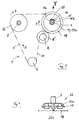
- camshafts 2, 3 which are driven by a chain drive designated in its entirety by 4.
- the camshafts 2, 3 have camshaft drive wheels 12, 13, via which a chain 10, which is also guided by a crankshaft wheel 6 and a deflection roller 8, runs.
- the shoulder 16 of the camshaft 3 becomes due to the resistance counteracting the camshaft rotation - caused by frictional moments and by the valve opening forces acting on the cams of the camshaft and caused by the valve springs - come to rest on the (left) shoulder 15a of the recess 15.
- a spring element 25 can be provided to assist between the shoulder 16 and the (right) shoulder 15b of the recess 15. In this position, the camshaft 3 is thus set in rotation in a first phase position synchronously with the camshaft 2 and the crankshaft gear 6.
- journal 14 of the camshaft 3 carries a gear element 18 designed as a pulley, which is connected via a traction means 19 to a pulley 20 arranged on the camshaft 2.
- a fluid friction clutch designated in its entirety with 22.
- the housing 22a of the fluid friction clutch is non-rotatably connected to the camshaft 2 and at the same time carries its drive wheel 12.
- the output shaft 22b of the fluid friction clutch 22, on the other hand, carries the pulley 20.
- the camshaft 3 connected to the transmission element 18 becomes closed when the fluid friction clutch 22 is closed 1 in relation to the drive wheel 13 in the direction of the arrow 9 until the shoulder 16 bears against the right shoulder 15b of the recess 15. Since the fluid friction clutch 22 allows slippage between the rotational movement of the drive shaft (camshaft 2 or housing 22a) and the output shaft 22b, the camshaft 3 is held in the position with its shoulder 16 on the right shoulder 15b of the drive wheel 13. On the other hand, when the fluid friction clutch 22 is released, the camshaft 3 moves with respect to the drive wheel 13 due to the moment of resistance counteracting its rotary movement and possibly under the influence of the spring element 25 into the position shown in FIG. 1.
- the embodiment variant already described above is not shown, in which a locking element rigidly connecting the camshaft to the drive wheel is provided.
- the fluid friction clutch instead of which a mechanical friction clutch or a viscosity clutch can be provided, is only closed until the camshaft 3 is in the desired position with respect to its drive wheel 13. Subsequently, the camshaft is rigidly connected to the drive wheel by engagement of the locking element, not shown, and the clutch is released. A return movement to the position shown in FIG. 1 also takes place automatically by releasing the latching element when the clutch is open due to the section modulus which counteracts the camshaft rotary movement.
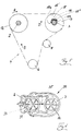
- FIGS. 3 and 4 A further embodiment principle is shown in FIGS. 3 and 4, the components already explained being designated by the same numbers.
- an energy storage element 25 in the form of, for example, a compression coil spring is clamped between the shoulder 16 of the camshaft 3 and the left shoulder 15a of the recess 15 of the drive wheel 13. Without the action of the element which can be connected to the transmission element via a switchable coupling and which has a rotational speed which differs from the drive wheel the camshaft 3 with respect to the drive wheel 13 is thus always held in the position shown under the influence of the energy storage element 25.
- the housing 22a of the fluid friction clutch 22 carries the camshaft drive wheel 13 and is rotatably supported on the camshaft 3 within the angular range delimited by the recess 15 and the shoulder 16.
- the output shaft 22b of the fluid friction clutch 22 carries the gear element 18, which is in drive connection with the deflection roller 8.
- the gear element 18 is designed as a gear which meshes with a counter gear 8 'arranged on the deflection roller 8'.
- the first vane wheel 31 of the vane pump 30 is rotatably connected to a rotating machine shaft, for example the camshaft 2.
- the second vane wheel 32 is connected to the camshaft 3 to be adjusted.
- a wall section 33 separating the two vane wheels from one another is displaceably arranged with respect to the first vane wheel 31.
- the first vane wheel 31 conveys the hydraulic medium of the vane pump almost completely to the vane wheel 32 according to the arrows shown, as a result of which the camshaft 3 experiences an acceleration torque which also acts in the direction of the arrow.
- the camshaft 3 is thus advanced with relaxation of the energy storage element 25 'and compression of the energy storage element 25 ⁇ .
Landscapes
- Engineering & Computer Science (AREA)
- General Engineering & Computer Science (AREA)
- Mechanical Engineering (AREA)
- Valve Device For Special Equipments (AREA)
- Valve-Gear Or Valve Arrangements (AREA)
Claims (6)
caractérisé en ce que le couplage (22) établit par l'intermédiaire d'une transmission de démultiplication (24 ou 8 et 18) une liaison entre l'arbre (3) et un autre arbre tournant du moteur à combustion interne (autre arbre à cames 2, poulie de renvoi 8).
caractérisé en ce qu'il est prévu un élément de verrouillage reliant solidement l'arbre (3) à la roue d'entraînement (13).
caractérisé en ce que l'accouplement (22) est constitué comme un accouplement à friction liquide ou comme un accouplement à friction mécanique.
caractérisé en ce que l'autre arbre tournant du moteur est couplé avec un appareil consommateur d'énergie.
caractérisé en ce que l'accouplement (22) et la transmission de démultiplication (24) sont conçus comme une pompe à cellules semi-rotatives (30), dont les roues à cellules semi-rotatives (31, 32) sont reliées sans pouvoir tourner à l'arbre (3) ou à l'autre arbre du moteur (autre arbre à cames 2) et dont la section de paroi (33) séparant l'une de l'autre les deux roues à cellules semi-rotatives (31, 32) peut être déplacée par rapport à l'une des deux roues à cellules semi-rotatives.
caractérisé en ce que la roue de transmission d'arbres (13) est montée de façon à pouvoir tourner sur un téton (14) de l'arbre (3) et présente dans la zone de palier l'évidement (15), dans lequel vient en prise l'appendice (16) qui fait office d'entraîneur, au moins un élément (25) accumulateur d'énergie étant inséré entre l'appendice (16) et l'évidement (15).
Applications Claiming Priority (2)
| Application Number | Priority Date | Filing Date | Title |
|---|---|---|---|
| DE3834857 | 1988-10-13 | ||
| DE3834857 | 1988-10-13 |
Publications (2)
| Publication Number | Publication Date |
|---|---|
| EP0363600A1 EP0363600A1 (fr) | 1990-04-18 |
| EP0363600B1 true EP0363600B1 (fr) | 1992-07-29 |
Family
ID=6365017
Family Applications (1)
| Application Number | Title | Priority Date | Filing Date |
|---|---|---|---|
| EP19890114778 Expired - Lifetime EP0363600B1 (fr) | 1988-10-13 | 1989-08-10 | Dispositif de décalage angulaire d'un arbre à cames |
Country Status (2)
| Country | Link |
|---|---|
| EP (1) | EP0363600B1 (fr) |
| DE (1) | DE58901942D1 (fr) |
Families Citing this family (4)
| Publication number | Priority date | Publication date | Assignee | Title |
|---|---|---|---|---|
| DE3929623A1 (de) * | 1989-09-06 | 1991-03-07 | Bayerische Motoren Werke Ag | Brennkraftmaschine mit nockenwellen und einer drehwinkelverstell-vorrichtung |
| US5823152A (en) * | 1995-06-14 | 1998-10-20 | Nippondenso Co., Ltd. | Control apparatus for varying a rotational or angular phase between two rotational shafts, preferably applicable to a valve timing control apparatus for an internal combustion engine |
| US6006709A (en) * | 1995-06-14 | 1999-12-28 | Nippondenso Co., Ltd. | Control apparatus for varying a rotational or angular phase between two rotational shafts, preferably applicable to a valve timing control apparatus for an internal combustion engine |
| DE59803257D1 (de) * | 1997-10-21 | 2002-04-11 | Tcg Unitech Ag Kirchdorf | Vorrichtung zur Verstellung einer Nockenwelle einer Brennkraftmaschine mit innerer Verbrennung |
Family Cites Families (2)
| Publication number | Priority date | Publication date | Assignee | Title |
|---|---|---|---|---|
| US4754727A (en) * | 1986-12-09 | 1988-07-05 | Eaton Corporation | Device for varying engine valve timing |
| US4762097A (en) * | 1986-12-29 | 1988-08-09 | General Motors Corporation | Engine with hydraulically variable cam timing |
-
1989
- 1989-08-10 DE DE8989114778T patent/DE58901942D1/de not_active Expired - Lifetime
- 1989-08-10 EP EP19890114778 patent/EP0363600B1/fr not_active Expired - Lifetime
Non-Patent Citations (1)
| Title |
|---|
| "Les mécanismes dans la technique moderne", I.ARTOBOLEVSKI, Tome 3, Mécanismes à engrenage, Editions MIR, Moscou, 1976, Seiten 585 -591 * |
Also Published As
| Publication number | Publication date |
|---|---|
| DE58901942D1 (de) | 1992-09-03 |
| EP0363600A1 (fr) | 1990-04-18 |
Similar Documents
| Publication | Publication Date | Title |
|---|---|---|
| DE3830382C1 (fr) | ||
| DE3825074C1 (fr) | ||
| EP2350442B1 (fr) | Système de réglage pour arbres à cames d'un moteur à combustion interne | |
| DE3624827A1 (de) | Verstelleinrichtung fuer eine nockenwelle zum steuern der gasein- und auslassventile von verbrennungsmotoren | |
| DE102006000026B4 (de) | Variable Ventilzeitsteuereinrichtung | |
| EP0295414A2 (fr) | Dispositif de commande de la soupape d'étranglement d'un moteur à combustion interne | |
| DE19804575A1 (de) | Variabler Ventilmechanismus sowie mit dem Ventilmechanismus versehener Verbrennungsmotor | |
| DE10224446A1 (de) | Vorrichtung zur relativen Winkelverstellung zwischen zwei rotierenden Elementen | |
| WO2007039103A1 (fr) | Moteur a combustion presentant un taux de compression variable | |
| WO2013164129A1 (fr) | Déphaseur d'arbre à cames | |
| DE102005059590A1 (de) | Trommelbremse | |
| EP2294289A1 (fr) | Unité d'arbre à cames | |
| DE102004033894A1 (de) | Nockenwellenverstelleinrichtung | |
| EP0363600B1 (fr) | Dispositif de décalage angulaire d'un arbre à cames | |
| EP0755892B1 (fr) | Dispositif pour rétracter et avancer un élément de manipulation ou de traitement de fil | |
| DE102008043673A1 (de) | Verstellsystem für Nockenwellen einer Brennkraftmaschine | |
| DE102014200331A1 (de) | Ölpumpenantrieb mit schaltbarer Antriebsübersetzung | |
| DE10236894B4 (de) | Ventilzeitensteuersystem für Verbrennungsmotor | |
| DE69013680T2 (de) | Phasenverschiebungsvorrichtung. | |
| DE3831788A1 (de) | Fliehkraftregler fuer einen verbrennungsmotor mit einspritzung | |
| DE3825355A1 (de) | Elektromagnetische kupplungsvorrichtung | |
| DE3939991C2 (fr) | ||
| EP0892482B1 (fr) | Frein associé à un moteur électrique | |
| WO2008089864A1 (fr) | Dispositif de déplacement pour le déplacement axial d'un arbre à cames au moyen d'un actionneur de déplacement | |
| DE3931848A1 (de) | Servolenkung fuer fahrzeuge |
Legal Events
| Date | Code | Title | Description |
|---|---|---|---|
| PUAI | Public reference made under article 153(3) epc to a published international application that has entered the european phase |
Free format text: ORIGINAL CODE: 0009012 |
|
| AK | Designated contracting states |
Kind code of ref document: A1 Designated state(s): DE FR GB IT SE |
|
| 17P | Request for examination filed |
Effective date: 19900518 |
|
| 17Q | First examination report despatched |
Effective date: 19910910 |
|
| GRAA | (expected) grant |
Free format text: ORIGINAL CODE: 0009210 |
|
| AK | Designated contracting states |
Kind code of ref document: B1 Designated state(s): DE FR GB IT SE |
|
| ET | Fr: translation filed | ||
| REF | Corresponds to: |
Ref document number: 58901942 Country of ref document: DE Date of ref document: 19920903 |
|
| GBT | Gb: translation of ep patent filed (gb section 77(6)(a)/1977) | ||
| ITF | It: translation for a ep patent filed | ||
| RAP4 | Party data changed (patent owner data changed or rights of a patent transferred) |
Owner name: BAYERISCHE MOTOREN WERKE AKTIENGESELLSCHAFT |
|
| PLBE | No opposition filed within time limit |
Free format text: ORIGINAL CODE: 0009261 |
|
| STAA | Information on the status of an ep patent application or granted ep patent |
Free format text: STATUS: NO OPPOSITION FILED WITHIN TIME LIMIT |
|
| 26N | No opposition filed | ||
| EAL | Se: european patent in force in sweden |
Ref document number: 89114778.7 |
|
| PGFP | Annual fee paid to national office [announced via postgrant information from national office to epo] |
Ref country code: SE Payment date: 19950726 Year of fee payment: 7 |
|
| PGFP | Annual fee paid to national office [announced via postgrant information from national office to epo] |
Ref country code: DE Payment date: 19950731 Year of fee payment: 7 |
|
| PGFP | Annual fee paid to national office [announced via postgrant information from national office to epo] |
Ref country code: GB Payment date: 19950807 Year of fee payment: 7 |
|
| PGFP | Annual fee paid to national office [announced via postgrant information from national office to epo] |
Ref country code: FR Payment date: 19950831 Year of fee payment: 7 |
|
| PG25 | Lapsed in a contracting state [announced via postgrant information from national office to epo] |
Ref country code: GB Effective date: 19960810 |
|
| PG25 | Lapsed in a contracting state [announced via postgrant information from national office to epo] |
Ref country code: SE Effective date: 19960811 |
|
| GBPC | Gb: european patent ceased through non-payment of renewal fee |
Effective date: 19960810 |
|
| PG25 | Lapsed in a contracting state [announced via postgrant information from national office to epo] |
Ref country code: FR Effective date: 19970430 |
|
| PG25 | Lapsed in a contracting state [announced via postgrant information from national office to epo] |
Ref country code: DE Effective date: 19970501 |
|
| EUG | Se: european patent has lapsed |
Ref document number: 89114778.7 |
|
| REG | Reference to a national code |
Ref country code: FR Ref legal event code: ST |
|
| PG25 | Lapsed in a contracting state [announced via postgrant information from national office to epo] |
Ref country code: IT Free format text: LAPSE BECAUSE OF NON-PAYMENT OF DUE FEES;WARNING: LAPSES OF ITALIAN PATENTS WITH EFFECTIVE DATE BEFORE 2007 MAY HAVE OCCURRED AT ANY TIME BEFORE 2007. THE CORRECT EFFECTIVE DATE MAY BE DIFFERENT FROM THE ONE RECORDED. Effective date: 20050810 |