EP0363640A2 - Terminal haute fréquence pour système de communication anti-brouillage - Google Patents
Terminal haute fréquence pour système de communication anti-brouillage Download PDFInfo
- Publication number
- EP0363640A2 EP0363640A2 EP89116457A EP89116457A EP0363640A2 EP 0363640 A2 EP0363640 A2 EP 0363640A2 EP 89116457 A EP89116457 A EP 89116457A EP 89116457 A EP89116457 A EP 89116457A EP 0363640 A2 EP0363640 A2 EP 0363640A2
- Authority
- EP
- European Patent Office
- Prior art keywords
- signal
- data
- coupled
- subsystem
- transmitting
- Prior art date
- Legal status (The legal status is an assumption and is not a legal conclusion. Google has not performed a legal analysis and makes no representation as to the accuracy of the status listed.)
- Granted
Links
Images


Classifications
-
- H—ELECTRICITY
- H04—ELECTRIC COMMUNICATION TECHNIQUE
- H04K—SECRET COMMUNICATION; JAMMING OF COMMUNICATION
- H04K1/00—Secret communication
-
- H—ELECTRICITY
- H04—ELECTRIC COMMUNICATION TECHNIQUE
- H04B—TRANSMISSION
- H04B1/00—Details of transmission systems, not covered by a single one of groups H04B3/00 - H04B13/00; Details of transmission systems not characterised by the medium used for transmission
- H04B1/69—Spread spectrum techniques
-
- H—ELECTRICITY
- H04—ELECTRIC COMMUNICATION TECHNIQUE
- H04K—SECRET COMMUNICATION; JAMMING OF COMMUNICATION
- H04K3/00—Jamming of communication; Counter-measures
- H04K3/20—Countermeasures against jamming
- H04K3/25—Countermeasures against jamming based on characteristics of target signal or of transmission, e.g. using direct sequence spread spectrum or fast frequency hopping
-
- H—ELECTRICITY
- H04—ELECTRIC COMMUNICATION TECHNIQUE
- H04K—SECRET COMMUNICATION; JAMMING OF COMMUNICATION
- H04K2203/00—Jamming of communication; Countermeasures
- H04K2203/10—Jamming or countermeasure used for a particular application
- H04K2203/16—Jamming or countermeasure used for a particular application for telephony
Definitions
- HF high frequency
- radio voice and data communications have increased in importance in recent years, especially for military applications.
- HF band 2 to 30 MHz
- the need for reliable HF communication links increases.
- error correction and spread spectrum signal processing techniques must be employed.
- Spread spectrum operation can be achieved by pseudo noise (PN) spreading in the modem or by frequency hopping (FH) the radio transmitter and receiver.
- PN pseudo noise
- FH frequency hopping
- Frequency hopping operation provides anti-jam or electronic counter counter measure operation (ECCM) capability while frequency hopping, pseudo noise spreading and the use of secure modem systems insure a low probability of intercept and a low probability of exploitation.
- ECCM electronic counter counter measure operation
- Frequency hopping combined with decision feedback equalization, linear intersymbol interference cancellation, error correction and interleaving in the modem subsystem gives frequency diversity and anti-jam capability.
- Very low bit rate voice communication in the voice subsystem is also provided by the high frequency communication system terminal.
- the modem subsystem uses PN spreading to employ the full bandwidth that is available and to provide additional anti-jam capability.
- the frequency hopping/PN technique also gives low probability of intercept capability if low transmission powers are used.
- spread spectrum communication systems have been used in a variety of fields.
- the transmitted bandwidth is much greater than the bandwidth or rate of the information to be transmitted.
- the carrier signal is modulated by some other function to widen or spread the bandwidth for transmission.
- the receive signal is remapped into the original information bandwidth to reproduce a desired signal.
- the spread spectrum communication system has many useful advantages, as is well known in the prior art. Such systems can be categorized into a direct sequence system, a frequency hopping system, a time hopping system and a hybrid system which is a proper combination of the systems just mentioned. Of these systems the frequency hopping system is frequently used in the field of mobile communication systems with a low traffic volume for a number of stations. Frequency hopping systems can be employed in satellite communication systems and scatter-type communications system where a fading environment is present.
- a carrier frequency is shifted or jumped in discrete increments in a pattern dictated by a prepared code or sequence, for instance, a PN code (pseudo noise), M sequence codes, Gold codes and the like in synchronism with a change in the state of the codes.
- the resulting consecutive and time sequential frequency pattern is called a hopping pattern and the duration of each hopping frequency is called a chip.
- the transmitted information is embedded in the codes or embedded in each frequency of the carrier wave by a so-called FSK (frequency shift keyed) or PSK (phase shift keyed) modulation.
- FSK frequency shift keyed
- PSK phase shift keyed
- a local reference signal of a frequency correspondingly determined by the same code pattern as that in the transmitter for every chip and the received signals are mixed in a mixer in order to perform a correlation (despreading) process for converting the spread spectrum signal into the signal having a frequency bandwidth wide enough to extract the information.
- This system is described in detail in "Spread Spectrum Systems” by R. C. Dixon published by John Wiley and Sons, Inc. (1976). Following this spreading process the desired information is extracted by usual demodulation techniques.
- the terminal to be described is interfaced to a radio that is capable of frequency hopping the packets provided by the terminal.
- a radio that is capable of frequency hopping the packets provided by the terminal.
- the system according to this invention employs two types of frequency hopping modes.
- the first type is a slow Hopping or High Data Rate (HDR) mode, which operates in 2400 bps voice, 2400 bps data or rekey modes.
- a Fast Hopping, or Low Data Rate (LDR) mode operates in 400 bps voice or rekey modes.
- the 2400 Voice Mode operates in conjunction with a standard voice processor utilizing linear predictive coding (LPC) which is well known in the prior art.
- LPC linear predictive coding
- the 400 Voice Mode has an additional voice processor function which converts standard 2400 LPC to 400 bits per second voice data.
- the modem to be described is a secure digital voice and data terminal. It is designed to interface with HF radios to provide a complete communication system.
- the terminal is particularly designed to interface with various military receivers, such as those manufactured by the Hughes Aircraft Company of California.
- Such radios implement frequency hopping modes which are compatible with the enhanced modes, as will be further described and which are available by the use of this terminal.
- the radio provides for the generation of the frequency hopping pattern and the actual shift in the carrier frequency. It also provides for the initial synchronization acquisition processes.
- the efficiency of the overall data signal is determined by the fraction of the packet which is used for training data.
- the packet duration for a high data rate system must be much longer than the multi-path spread.
- a high data rate system, using slow frequency hopping, is more susceptible to jamming.
- fast frequency hopping systems are limited to incoherent modulation without any training signals which inherently provide a lower data rate.
- a system which uses a training signal it is desirable that the data pattern by randomized by PN coding or the like so that it is different for each frequency hop. If it is the same for every frequency hop the system is easier to jam because the fixed training sequence can be transmitted as a jamming signal. However, it is more difficult to use a training signal which is different for each frequency hop.
- a high frequency communication system of the type employing a high frequency terminal which terminal can transmit a processed signal in a transmitting mode or process a received signal in a receiving mode
- which terminal includes a first subsystem for voice processing including a processor responsive to voice signals to provide a linear predictive coded voice signal at a given data rate, which signal is coupled to a data modem subsystem to digitally encrypt said voice signal which data modem subsystem is coupled to a modem processor subsystem capable of processing said encrypted signal for providing frequency hopping, feedback equalization, intersymbol interference cancellation, error correction and interleaving to provide a transmitted signal which is relatively immune to jamming during said transmitting mode
- the improvement therewith of apparatus for providing an improved transmitting operation comprising a convolutional encoder means included in said modem processor subsystem and responsive to said encrypted signal to provide a convoluted signal at a higher data rate than said encrypted signal at an output an interleave buffer having an input coupled to said encoder output for interleaving said higher data rate signal according to an
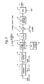
- FIG. 1 there is illustrated a general block diagram of a terminal for a high frequency frequency hopping communication system in accordance with the principles of the present invention.
- the first subsystem 10 is a voice processing system which typically includes a handset 13 which is coupled to an input/output device 11.
- the input/output device 11 is bidirectionally coupled to a voice processor 12.
- the voice processor 12 utilizes linear predictive coding (LPC) to provide voice communication at 2400 bits per second.
- LPC linear predictive coding
- the processor also provides state of the art low bit rate voice communications at 400 bits per second.
- a modem system 20 Coupled to the subsystem 10, as indicated briefly above, is a modem system 20.
- the modem system 20 is also well known and provides for digital encryption of the 2400 and 400 bits per second data signal.
- the modem 20 thus enables the system to provide secure communication of voice and data.
- Subsystem 30 contains two modem processors, namely 15 and 17. As will be explained, the modem processors operate to control the modem 14 and to also interface with an input/output device 16 which interfaces directly with a radio transceiver 18 for the transmission or reception of radio signals via the antenna 19.
- the subsystem 30 essentially is a modem processor system which employs state of the art equalization techniques and signal processing. It provides for 2400 and 400 bits per second data communication on 3 KHZ high frequency channels with frequency hopping by the external HF radio 18. Frequency hopping, combined with decision feedback equalization, linear intersymbol interference cancellation, error correction and interleaving in the modem subsystem 30 gives frequency diversity and anti-jam capability.
- the high frequency communication system provides the following capabilities.
- FIG. 1 Essentially data flow through the terminal is shown in FIG. 1 and operates as follows. First assume that a voice mode has been selected. For a voice mode the handset 13 signal is digitized by means of the input/output device 11 which essentially contains an 8.0 KHZ Codec and this digital information is sent to the voice processor unit 12 for rate reduction to 2400 bits per second or according to a 400 bit per second algorithm.
- the output signal from the voice processor 12 is coupled to the modem 14 where it is encrypted and passed to the modem processor module 30.
- the encrypted signal is encoded, modulated and filtered by the modem processors 15 and 17 before it is sent to the I/O device 16.
- the I/O device 16 operates to convert the digital signal to an analog signal by the use of a D/A converter which is performed by a 7.2 kHz Codec.
- the analog signal is then coupled to the external radio 18 where it is transmitted.
- the radio 18 acquires synchronization and sends the audio signal to the I/O device 16 for processing.
- This audio signal is digitized by the I/O device and passed to modem processor 15 and modem processor 17 where it is demodulated and decoded.
- the decoded data are sent to the modem 14 for decryption and then to the voice processor 12 where the compressed voice is restored to full rate.
- the full data rate is then converted by means of a digital to analog converter by the codec contained in the I/O device 11 and then sent to the handset 13 for the listener to respond to.
- terminal non-hopping modes can be selected and configured with a corresponding non-hopping modem.
- voice data which is digitized by the input/output device 11
- the modem processor where it is then converted to analog information by input/output device 16 and transmitted directly by the radio transceiver 18.
- the present system utilizes an anti-jamming technique where either of the above-described hopping modes can be selected and configured with a corresponding hopping radio depending upon the nature of the threat.
- the system as shown generally in FIG. 1, employs many of the same components and subsystems as shown and completely described in the above-noted copending application which is incorporated herein.
- the signal processing in a modem subsystem 30 can be described by two different sets of algorithms.
- the high data rate (HDR) algorithms are used when the data rates are 2400 bits per second. These algorithms are used when the frequency hopping rate is slow. These algorithms, as will be explained, are similar to those described in the above-noted co-pending application. The differences between the algorithms employed according to this invention will be described below.
- the low data rate (LDR) algorithms are used when the data rates are 400 bits per second.
- the LDR algorithms are used when the frequency hopping rate is fast.
- the modem subsystem 30 processes data separately during each frequency hop.
- the data transmitted during one frequency hop is called a packet.
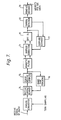
- the packet formats for the two modes of operation are shown in FIG. 2.
- FIG. 2A there is shown the packet format for the high data rate (HDR) mode.
- HDR high data rate
- the packet in the HDR mode is divided into blocks of PN training symbols, T0... to T5 and blocks of data symbols D1... to D5.
- Each data block is short relative to the fading rate of the HF channel so that the channel impulse response does not change appreciably during a block.
- the duration of the training blocks is greater than the duration of the expected multipath spread.
- FIG. 2B there is shown the packet format for the LDR mode or the low data rate mode.
- data is separated by idle time.
- the first portion of the data interval is designated as a guard interval while the second portion is a DFT integration interval where DFT stands for Discrete Fourier Transform. This transform is employed by the system to implement operation as will be explained.
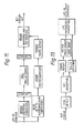
- the algorithm for the transmitter function for the HDR mode is shown.
- a difference between this algorithm and the algorithms contained in the above-noted application is that a randomized PN training signal indicated by module 39 is used such that it is different for each and every frequency hop. This is done to make the system harder to jam.
- the main algorithms and the HDR transmitter function which are the same as in the previous invention, are the convolution error correction encoder 31 and the interleave buffer 32 which interleaves the data.
- the interleave buffer 32 is coupled to the input of an 8 PSK symbol encoder which phase shift key modulates the data symbols and the output of the encoder 33 is coupled to the transmit filter 34 (TX) which services to filter the encoder symbols.
- TX transmit filter 34
- the symbol encoder 33 is operated on by the pseudo noise training signal module 39.
- the output of the transmit shaping filter 34 is applied to a multiplier 35 which takes the symbol output from the filter 34, which is at a sample rate of 7200 HZ, and multiplies the symbols by an exponential function, as indicated in the Figure where fc equals 1800.
- the output of the multiplier is sent to a sample buffer 39 whereby the samples of buffer 36 are converted to analog signals in the digital to analog converter 37.
- This digital to analog converter 37 operates at a 7200 Hz sampling rate to provide the analog transmit signal which is the signal coupled to the radio transceiver 18 and transmitted via antenna 19.
- FIG. 3 the modules contained in FIG. 3 are implemented by means of the modem A processor 15 and the modem B processor 17 of FIG. 1. These processors, as will be further explained, operate in conjunction with one another and modem B processor 17 operates to exchange data and control signals with the modem A processor 15.
- the digital to analog converter 37 is contained in the input/output module 16 of FIG. 1 which is coupled to the modem A processor 15 and modem B processor 17.
- the convolutional encoder 31 operates on the 2400 bit per second input which is obtained from the output of the modem 14 of FIG. 1 and operates according to a fixed coefficient K to multiply the effective bit rate by 3/2 to obtain a 3600 bits per second signal at the output.
- the function of the convolution encoder is to essentially scramble the bits to insure randomness over a packet interval.
- the interleave buffer 32 contains an interleaving algorithm which is implemented by the modem A processor.
- the PSK encoder 33 modulates the output data from the interleave buffer into a phase shift key signal which is then operated on by a randomized PN training signal 39 which is stored in the modem processor.
- the PN training signal as stored is a block of known PN training signals.
- the algorithm for the receiving function in the HDR mode is shown in FIG. 4.
- the main differences between this algorithm and that of the previous invention is the means for making the HF channel impulse response estimate, the precanceller 46 and the algorithms for calculating the equalizer coefficients and for performing equalization.
- the other algorithms in the receiver which are the same as in the previous co-pending application, are the analytic filter 43 which generates a complex form of the receive signal, the matched filter 48, which minimizes the effect of noise, the decision feedback filter 53, the de-interleave buffer 55, and the Viterbi decoder 56.
- the channel estimate algorithm uses the blocks of known PN training symbols to make an initial estimate of the HF channel impulse response and to update this estimate during the packet.
- the estimate used to calculate the matched filter and equalizer parameters for data block D k uses training blocks T0,...,T k (FIG. 2)
- a least squares algorithm is used to estimate the channel impulse response based on observations of the channel output in response to a known training sequence as channel input.
- M be the maximum number of symbols duration of the channel impulse response
- N+M be the number of training symbols in a training block.
- the received signal at 2400 HZ is converted to a digital signal by the A/D converter 40 which is sampled at 7200 Hz or at three times the input data rate.
- the receive signal is sampled at three times the symbol rate, that is, there are three channel output samples for every input symbol.
- the output bits of A/D converter 40 are stored in buffer 41 and are scaled accordingly by scaling module 42 to provide 3 samples for each input symbol.
- the channel output which is observed is: That is, the observation samples y′ n′ are not necessarily just the ideal response to the channel impulse response to the training sequence.
- the reason for this grouping is that the estimate for each group is independent of the other groups.
- the algorithm is applied three times to each group v separately.
- the covariance matrix and cross-correlation vector used to make the estimate for data block D k are defined as where the bar denotes complex conjugate, O ⁇ pw ⁇ l and the summations are over the last N symbols in the training block T k .
- R ji (k) and Q l (v,k) are zero for k ⁇ 0.
- the normal equations are a set of M linear, simultaneous equations which are solved for each v separately to give the estimate w j (v) used to calculate the matched filter 48 and equalizer parameters for data block D k .
- a Choleski decomposition algorithm is used for this solution.
- the decision feedback equalization algorithm processes each data block independently. For each symbol decision, via module 54, the intersymbol interference due to two sets of known symbols are cancelled. This is accomplished by the pre-canceller 46 and feedback filter 53 using the canceller coefficients 52. The coefficients 52 are applied to convolution with canceller module 49.
- the convolution module 49 has the output coupled to a long division module 50 which receives an input from autocorrelation module 51 which also supplies an input to canceller coefficient module 52.
- the module 49 and the long division module 50 perform an equalizer function.
- the cancelled symbols are symbols previous to the present data symbol and symbols which follow the present symbol. Previous known symbols can be either training symbols or data symbols already decided. These are cancelled by the feedback canceller in module 49. Intersymbol interference due to data symbols which follow the present data symbol is minimized by the equalizer of modules 49 and 50.
- the known symbols which follow the present data symbol are the training symbols in the training block immediately following the present data block. These are cancelled by the pre-canceller 46.
- the pre-canceller 46 uses cancellation prior to the matched filter 48 and equalizer and allows the receive samples to be separated into blocks for independent processing. This, in turn, allows the use of the long division equalizer algorithm discussed below.
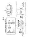
- FIG. 5 illustrates the pre-cancellation algorithm.
- the first figure A shows the present data block of K symbols, M known "guard" (training) symbols and subsequent data (or training) symbols.
- the pre-cancellation algorithm removes the effect on the receive samples of both the guard and subsequent data symbols. The result is as if nothing follows the present transmitted data block.
- the second diagram B illustrates the channel impulse response.
- the channel output, shown in C is the result of convolving this impulse response with the transmit symbols.
- the channel response causes the present data block to be spread out to cover K+M symbol intervals. In addition, it causes response due to the guard symbols to overlap the last M symbol intervals.
- the pre-canceller 46 generates this overlapping response by convolving the known guard symbols with the channel estimate and subtracting it from the receive samples. This removes the effect of the guard symbols from the M overlapping symbol intervals. The receive samples beyond these overlapping symbols are zeroed. The result is a block of 3(K+M) receive samples which are passed through the matched filter 48.
- the decision feedback filter 53 is initialized with the M known training symbols immediately prior to the present data block. In this way, their intersymbol interference is cancelled from the beginning of the present data block. Thus, the receive samples due to the present block of data symbols are isolated for subsequent processing by the matched filter and equalizer.
- the equalizer was a feedforward transversal filter with K taps.
- the transfer function of this filter can be written as The processing is on stored blocks of data so that even though this transfer function is of an anti-causal filter, it is realizable in the modem application.
- G(z) is a finite polynomial in z with K non-zero coefficients.
- M(z) is also a finite polynomial with 2M-1 non-zero coefficients in the range of z -(M-1) to 3 (M-1 .
- the coefficient of z k is the complex conjugate of the coefficient of z -k .
- C(z) is a finite polynomial with non-zero coefficients in the range of z -(m-1) to z (m+k-2) .
- the linear equations in the previous invention served to constrain the coefficients of C(z) in the range z0 to z (K-1) ; the coefficient of z0 being 1 and the other 0. the remaining coefficients represent the canceller coefficients.
- the coefficients of z ⁇ 1 to z -(M-1) are the coefficients of the decision feedback filter.
- the coefficients of z K to z K+M-2 are the coefficients of a feedforward canceller filter which is not needed because its function is performed by the pre-canceller.
- this algorithm the output of the matched filter 48 and T sampler switch (T sampling) is first convolved with the coefficients of C(z). Then the result is divided by the polynomial M(z).
- This has significant processing advantage when the length of the data block K is relatively long compared with the duration of the maximum multipath spread M.
- K a recursion for C(z) involving only 2M-1 non-zero coefficients is used.
- the equalizer filter of length K convolution with the 2M-1 coefficients of C(z) and division by the 2M-1 coefficients of M(z) is used.
- C m (z) has only 2M-1 non-zero coefficients of which the coefficient of z0 is unity.
- the coefficients of (z m , ⁇ ,z) are constrained to be zero by the recursion.
- D m (Z) also has only 2M-1 non-zero coefficients of which the coefficient of z M-1 is M M-1 and the coefficients of (z ⁇ 1, ⁇ ,z -m ) are constrained to be zero by the recursion.
- the recursions for C m (z) and D m (z) require only 4(M-1) coefficient updates per iteration.
- the algorithm and functional data flow for the transmitter functions of the modem subsystem operating in the LDR mode is shown in FIG. 6.
- the input data rate is 400 bits per second.
- These data bits are encoded by the rate 2/3 Reed-Solomon (RS) error correction coder 60 to give 600 bits per second in the form of 6 bit groups, each group corresponding to a RS codeword symbol.
- RS Reed-Solomon
- a sequence of eight known PN symbols are transmitted to allow the receiver to make an initial Doppler frequency estimate. This is done via module 66 coupled to symbol encoder 61.
- Each 6 bit symbol is transmitted as a different frequency hopping packet. This gives the system a form of diversity which minimizes the effect of fading on the HF channel. Since each symbol is on a different frequency, it fades independently of the other symbols in a 63 symbol RS codeword. The code has a 21 symbol redundancy which means that up to 10 symbols can fade without causing a decoding error.
- the transmitter uses a Discrete Fourier Transform (DFT) 62 to generate 24 tone slots spaced by 150 Hz.
- DFT Discrete Fourier Transform
- the tone map function selects 2 tone frequencies out of 12 of these tone slots which may be used for a transmit signal. There are 66 such combinations possible of which only 64 are needed for a 6 bit symbol.
- a DFT 70 is used to measure the complex amplitude of receive tones and the 12 tone slots.
- Doppler correction 71 of the receive signal is provided to ensure that the receive tones are properly centered in their tone slots. This is accomplished by providing a Doppler estimate in module 77 by comparing the output of the DFT 70 with the detected symbols from module 72 to arrive at an error signal used to compensate the input signals to the DFT 70 via the Doppler correction 71.
- Symbol detection 72 is done by determining the two tone slots which have the greatest receive energy, i.e., have the greatest magnitude. This form of incoherent detection does not require any training and is independent for each frequency hop.
- the RS decoding 73 provides protection against fading and jamming of some of the symbols in a codeword.
- the packet format provides for a guard interval before the samples are processed by the DFT 70. This interval is greater than the expected multipath duration so that the tone signals settle to a steady state before the DFT operation. This provides the system with immunity to multipath spread of the HF channel. In addition, the symbol duration is very short with this fast frequency hopping made so that the system is not affected by fading rates normally experienced on a HF channel.
- the receive samples for each packet are stored in the receive sample buffer 74.
- the packet boundaries are determined by the frequency hopping clock from the HF radio.
- the modem uses a further timing estimate of the position of the receive data baud within this buffer. This is done by scaling the received samples in module 75 and using a baud sync tracking module 76 for control of the receive sample buffer 74. This is necessary to properly position the DFT integration window to follow the multipath guard interval and to track any drift in the HF radio clock.
- this function uses early and late windows at the edges of the Rx baud.
- the window positions selected are at the beginning and end of the expected baud position in the receive sample buffer.
- the sum of the squares of the receive samples within the early and late windows, respectively, are accumulated.
- the output timing error estimate is the difference between these two energies.
- the doppler frequency offset in the receive signal is compensated for with a doppler correction operation using an estimated doppler frequency.
- the known tone sequence is used with the receive tone amplitudes to estimate the residual frequency error after doppler correction.
- the error signal is used in a feedback loop to correct the estimated doppler frequency (FIG. 9).
- a loop filter is used to give a second order loop response.
- the receive tone amplitudes are used by the symbol detection function to determine the two tones with the largest amplitude. This determines the receive symbol and also an array itones which is for use in estimating the residual doppler error. This array has a one in the two locations corresponding to the largest receive tones and zeros otherwise.
- the doppler estimate function uses the actual receive tone amplitudes and the itones array.
- the discrete Fourier transform determines the complex amplitude in each of 24 tone slots.
- the equivalent response of each tone slot has a characteristic. This causes significant sidelobes in the raw tone amplitudes. These sidelobes are reduced and the tone slot width is broadened in the subroutine by a Hanning operation. This convolves the complex tone amplitudes with the sequence (.5,1,.5).
Landscapes
- Engineering & Computer Science (AREA)
- Computer Networks & Wireless Communication (AREA)
- Signal Processing (AREA)
- Radar, Positioning & Navigation (AREA)
- Remote Sensing (AREA)
- Cable Transmission Systems, Equalization Of Radio And Reduction Of Echo (AREA)
- Transmission Systems Not Characterized By The Medium Used For Transmission (AREA)
- Digital Transmission Methods That Use Modulated Carrier Waves (AREA)
Applications Claiming Priority (2)
| Application Number | Priority Date | Filing Date | Title |
|---|---|---|---|
| US07/256,342 US4914699A (en) | 1988-10-11 | 1988-10-11 | High frequency anti-jam communication system terminal |
| US256342 | 1988-10-11 |
Publications (3)
| Publication Number | Publication Date |
|---|---|
| EP0363640A2 true EP0363640A2 (fr) | 1990-04-18 |
| EP0363640A3 EP0363640A3 (fr) | 1992-03-18 |
| EP0363640B1 EP0363640B1 (fr) | 1997-01-15 |
Family
ID=22971890
Family Applications (1)
| Application Number | Title | Priority Date | Filing Date |
|---|---|---|---|
| EP89116457A Expired - Lifetime EP0363640B1 (fr) | 1988-10-11 | 1989-09-06 | Terminal haute fréquence pour système de communication anti-brouillage |
Country Status (3)
| Country | Link |
|---|---|
| US (1) | US4914699A (fr) |
| EP (1) | EP0363640B1 (fr) |
| DE (1) | DE68927658T2 (fr) |
Cited By (5)
| Publication number | Priority date | Publication date | Assignee | Title |
|---|---|---|---|---|
| EP0529051A4 (fr) * | 1991-03-13 | 1994-12-14 | Motorola Inc | |
| EP0792050A3 (fr) * | 1996-02-20 | 2000-10-18 | International Business Machines Corporation | Distribution de symboles de références dans une trame |
| WO2001013537A1 (fr) * | 1999-08-12 | 2001-02-22 | Ericsson Inc | Estimation de l'etalement doppler a l'aide d'hypotheses de fonction d'autocorrelation de canal |
| KR20010046952A (ko) * | 1999-11-16 | 2001-06-15 | 배동만 | 제밍 방지 무선 송수신 방법 |
| US6760438B1 (en) * | 1999-07-01 | 2004-07-06 | Nortel Networks Limited | System and method for Viterbi decoding on encrypted data |
Families Citing this family (49)
| Publication number | Priority date | Publication date | Assignee | Title |
|---|---|---|---|---|
| US5128957A (en) * | 1990-08-10 | 1992-07-07 | Ricoh Company, Ltd. | Initial acquisition method in spread spectrum system and such system |
| JPH0777362B2 (ja) * | 1990-08-28 | 1995-08-16 | クラリオン株式会社 | スペクトラム拡散通信装置 |
| US5081643A (en) * | 1990-11-16 | 1992-01-14 | Scs Mobilecom, Inc. | Spread spectrum multipath receiver apparatus and method |
| US5390207A (en) * | 1990-11-28 | 1995-02-14 | Novatel Communications Ltd. | Pseudorandom noise ranging receiver which compensates for multipath distortion by dynamically adjusting the time delay spacing between early and late correlators |
| US5265190A (en) * | 1991-05-31 | 1993-11-23 | Motorola, Inc. | CELP vocoder with efficient adaptive codebook search |
| US5345467A (en) * | 1991-07-10 | 1994-09-06 | Interdigital Technology Corp. | CDMA cellular hand-off apparatus and method |
| US5259030A (en) * | 1991-07-17 | 1993-11-02 | Harris Corporation | Antijam improvement method and apparatus |
| US5255339A (en) * | 1991-07-19 | 1993-10-19 | Motorola, Inc. | Low bit rate vocoder means and method |
| US5301274A (en) * | 1991-08-19 | 1994-04-05 | Multi-Tech Systems, Inc. | Method and apparatus for automatic balancing of modem resources |
| US5150378A (en) * | 1991-10-07 | 1992-09-22 | General Electric Company | Method and apparatus for coherent communications in non-coherent frequency-hopping system |
| US5282222A (en) * | 1992-03-31 | 1994-01-25 | Michel Fattouche | Method and apparatus for multiple access between transceivers in wireless communications using OFDM spread spectrum |
| USRE37802E1 (en) | 1992-03-31 | 2002-07-23 | Wi-Lan Inc. | Multicode direct sequence spread spectrum |
| US5233626A (en) * | 1992-05-11 | 1993-08-03 | Space Systems/Loral Inc. | Repeater diversity spread spectrum communication system |
| US5657342A (en) * | 1992-10-23 | 1997-08-12 | Olmstead; David | Adaptive data rate packet communication system |
| US5995539A (en) * | 1993-03-17 | 1999-11-30 | Miller; William J. | Method and apparatus for signal transmission and reception |
| US5367516A (en) * | 1993-03-17 | 1994-11-22 | Miller William J | Method and apparatus for signal transmission and reception |
| GB9312836D0 (en) * | 1993-06-22 | 1993-08-04 | Schlumberger Ind Ltd | Multipoint to point radiocommunications network |
| EP0744101B1 (fr) * | 1994-02-10 | 1998-08-05 | International Business Machines Corporation | Procede et appareil de reduction des perturbations dues aux utilisateurs multiples |
| US5859874A (en) * | 1994-05-09 | 1999-01-12 | Globalstar L.P. | Multipath communication system optimizer |
| US5638399A (en) * | 1994-11-15 | 1997-06-10 | Stanford Telecommunications, Inc. | Multi-beam satellite communication system with user terminal frequencies having transceivers using the same set of frequency hopping |
| KR100272472B1 (ko) * | 1995-09-19 | 2000-11-15 | 씨. 필립 채프맨 | 디지탈 프로그램가능 임계 레벨을 가진 마이크로컨트롤러 재작동 기능 |
| US5754599A (en) * | 1996-01-04 | 1998-05-19 | Motorola, Inc. | Method and apparatus for coherent channel estimation in a communication system |
| US6678311B2 (en) | 1996-05-28 | 2004-01-13 | Qualcomm Incorporated | High data CDMA wireless communication system using variable sized channel codes |
| US6192068B1 (en) | 1996-10-03 | 2001-02-20 | Wi-Lan Inc. | Multicode spread spectrum communications system |
| US5898728A (en) * | 1996-11-22 | 1999-04-27 | Trw Inc. | Distributed analog-digital frequency dehopping system |
| US5954839A (en) * | 1997-01-14 | 1999-09-21 | Samsung Electronics Co., Ltd. | Error protection method for multimedia data |
| IL120222A0 (en) * | 1997-02-14 | 1997-06-10 | D S P C Israel Ltd | Method and apparatus for acquiring and tracking the sampling phase of a signal |
| US6603801B1 (en) * | 1998-01-16 | 2003-08-05 | Intersil Americas Inc. | Spread spectrum transceiver for use in wireless local area network and having multipath mitigation |
| US6661996B1 (en) | 1998-07-14 | 2003-12-09 | Globalstar L.P. | Satellite communication system providing multi-gateway diversity to a mobile user terminal |
| US6584140B1 (en) * | 1999-01-22 | 2003-06-24 | Systems Information And Electronic Systems Integration Inc. | Spectrum efficient fast frequency-hopped modem with coherent demodulation |
| KR100294070B1 (ko) | 1999-06-23 | 2001-06-15 | 박태진 | 이중주파수도약 통신 시스템 및 제어방법 |
| US6850505B1 (en) * | 1999-09-01 | 2005-02-01 | Telefonaktiebolaget L M Ericsson (Publ) | Method and apparatus for Doppler frequency estimation |
| US6879640B1 (en) * | 1999-10-20 | 2005-04-12 | Broadcom Corporation | Method, apparatus and system for high-speed transmission on fiber optic channel |
| US7027418B2 (en) | 2001-01-25 | 2006-04-11 | Bandspeed, Inc. | Approach for selecting communications channels based on performance |
| WO2002071981A1 (fr) * | 2001-03-09 | 2002-09-19 | Mobilian Corporation | Recepteur sans fil equipe d'un antibrouillage |
| US6735264B2 (en) | 2001-08-31 | 2004-05-11 | Rainmaker Technologies, Inc. | Compensation for non-linear distortion in a modem receiver |
| US7173966B2 (en) * | 2001-08-31 | 2007-02-06 | Broadband Physics, Inc. | Compensation for non-linear distortion in a modem receiver |
| US7269233B2 (en) * | 2003-01-27 | 2007-09-11 | Novatek Microelectronics Corp. | Algorithm of bit synchronization for a digital FSK correlation receiver |
| JP2005286729A (ja) * | 2004-03-30 | 2005-10-13 | Sanyo Electric Co Ltd | 同期捕捉回路およびそれを利用した受信装置 |
| US7483671B2 (en) * | 2005-05-19 | 2009-01-27 | The United States Of America As Represented By The Secretary Of The Navy | Processor based frequency selective jamming and communications system |
| US20090103720A1 (en) * | 2005-06-07 | 2009-04-23 | Manoj Karayil Thekkoott Narayanan | Method and system for secure and anti jamming wireless communication with high spectral efficiency |
| KR100728257B1 (ko) * | 2005-10-27 | 2007-06-13 | 한국전자통신연구원 | 채널 특성 변화를 이용한 판정 궤환 등화 장치 및 그 방법 |
| US8300813B1 (en) * | 2008-02-02 | 2012-10-30 | The Boeing Company | Secure information transfer based on global position |
| US8249540B1 (en) | 2008-08-07 | 2012-08-21 | Hypres, Inc. | Two stage radio frequency interference cancellation system and method |
| US8849213B2 (en) * | 2009-01-21 | 2014-09-30 | Bandspeed, Inc. | Integrated circuit for signal analysis |
| US8447252B2 (en) * | 2009-01-21 | 2013-05-21 | Bandspeed, Inc. | Adaptive channel scanning for detection and classification of RF signals |
| US20120177086A1 (en) * | 2010-11-09 | 2012-07-12 | Space Administration | System And Apparatus Employing Programmable Transceivers |
| US11050443B1 (en) | 2020-09-18 | 2021-06-29 | Rockwell Collins, Inc. | Beyond line of sight waveform and line of sight waveform software-defined radio |
| US11632143B1 (en) | 2020-09-18 | 2023-04-18 | Rockwell Collins, Inc. | Multiple channel beyond line of sight waveform software-defined radio |
Family Cites Families (3)
| Publication number | Priority date | Publication date | Assignee | Title |
|---|---|---|---|---|
| DE3023375C1 (fr) * | 1980-06-23 | 1987-12-03 | Siemens Ag, 1000 Berlin Und 8000 Muenchen, De | |
| US4365338A (en) * | 1980-06-27 | 1982-12-21 | Harris Corporation | Technique for high rate digital transmission over a dynamic dispersive channel |
| US4761796A (en) * | 1985-01-24 | 1988-08-02 | Itt Defense Communications | High frequency spread spectrum communication system terminal |
-
1988
- 1988-10-11 US US07/256,342 patent/US4914699A/en not_active Expired - Lifetime
-
1989
- 1989-09-06 DE DE68927658T patent/DE68927658T2/de not_active Expired - Lifetime
- 1989-09-06 EP EP89116457A patent/EP0363640B1/fr not_active Expired - Lifetime
Cited By (5)
| Publication number | Priority date | Publication date | Assignee | Title |
|---|---|---|---|---|
| EP0529051A4 (fr) * | 1991-03-13 | 1994-12-14 | Motorola Inc | |
| EP0792050A3 (fr) * | 1996-02-20 | 2000-10-18 | International Business Machines Corporation | Distribution de symboles de références dans une trame |
| US6760438B1 (en) * | 1999-07-01 | 2004-07-06 | Nortel Networks Limited | System and method for Viterbi decoding on encrypted data |
| WO2001013537A1 (fr) * | 1999-08-12 | 2001-02-22 | Ericsson Inc | Estimation de l'etalement doppler a l'aide d'hypotheses de fonction d'autocorrelation de canal |
| KR20010046952A (ko) * | 1999-11-16 | 2001-06-15 | 배동만 | 제밍 방지 무선 송수신 방법 |
Also Published As
| Publication number | Publication date |
|---|---|
| DE68927658T2 (de) | 1997-07-24 |
| EP0363640B1 (fr) | 1997-01-15 |
| DE68927658D1 (de) | 1997-02-27 |
| EP0363640A3 (fr) | 1992-03-18 |
| US4914699A (en) | 1990-04-03 |
Similar Documents
| Publication | Publication Date | Title |
|---|---|---|
| US4914699A (en) | High frequency anti-jam communication system terminal | |
| US7173966B2 (en) | Compensation for non-linear distortion in a modem receiver | |
| US4761796A (en) | High frequency spread spectrum communication system terminal | |
| KR960003835B1 (ko) | 신호 가중 시스템 | |
| EP0944977B1 (fr) | Procede et appareil de detection de symboles numeriques par utilisation d'estimations de reactions du support de transmission | |
| CA1139884A (fr) | Systeme semi-duplex a vocoder et modem integres | |
| US5956624A (en) | Method and system for simultaneously broadcasting and receiving digital and analog signals | |
| KR20040041590A (ko) | 모뎀 수신기에서의 비선형적인 왜곡 보상 | |
| EP0422467B1 (fr) | Modem haute fréquence à débit de données élevé | |
| EP1105977B1 (fr) | Recepteur adaptatif a propagation sur plusieurs voies pour systeme amcr de telecommunications | |
| US5497398A (en) | Multi-carrier transceiver | |
| CN102007703B (zh) | 通过协方差根处理的连续干扰减去的方法和设备 | |
| CN111628816B (zh) | 一种卫星通信系统的窄带干扰抑制方法 | |
| EP0566257A1 (fr) | Procédé et dispositif pour diversité d'antenne | |
| US6353627B1 (en) | High data rate spread-spectrum system and method | |
| US20050141603A1 (en) | Method and apparatus for signal transmission and reception | |
| JP5295182B2 (ja) | 信号の受信方法及び受信装置 | |
| US20020006157A1 (en) | System and method for peak power reduction in spread spectrum communications systems | |
| EP0674823B1 (fr) | Estimation du gain de trajet dans un recepteur | |
| US10447340B2 (en) | Devices and methods employing hermetic transforms for encoding and decoding digital information in spread-spectrum communication systems | |
| US7310286B1 (en) | System for undersea digital acoustic communications | |
| US20030236072A1 (en) | Method and apparatus for estimating a channel based on channel statistics | |
| KR20210023652A (ko) | 수중통신 성능향상을 위한 가중화된 다중밴드 신호 수신 방법 및 장치 | |
| US7577190B2 (en) | Method for prediction of a channel coefficient | |
| US6570842B1 (en) | System and apparatus for designing and producing signalling waveforms for direct-sequence code division multiple access communications |
Legal Events
| Date | Code | Title | Description |
|---|---|---|---|
| PUAI | Public reference made under article 153(3) epc to a published international application that has entered the european phase |
Free format text: ORIGINAL CODE: 0009012 |
|
| AK | Designated contracting states |
Kind code of ref document: A2 Designated state(s): DE FR GB IT |
|
| PUAL | Search report despatched |
Free format text: ORIGINAL CODE: 0009013 |
|
| AK | Designated contracting states |
Kind code of ref document: A3 Designated state(s): DE FR GB IT |
|
| 17P | Request for examination filed |
Effective date: 19920914 |
|
| 17Q | First examination report despatched |
Effective date: 19930803 |
|
| GRAG | Despatch of communication of intention to grant |
Free format text: ORIGINAL CODE: EPIDOS AGRA |
|
| GRAH | Despatch of communication of intention to grant a patent |
Free format text: ORIGINAL CODE: EPIDOS IGRA |
|
| GRAH | Despatch of communication of intention to grant a patent |
Free format text: ORIGINAL CODE: EPIDOS IGRA |
|
| GRAA | (expected) grant |
Free format text: ORIGINAL CODE: 0009210 |
|
| AK | Designated contracting states |
Kind code of ref document: B1 Designated state(s): DE FR GB IT |
|
| REF | Corresponds to: |
Ref document number: 68927658 Country of ref document: DE Date of ref document: 19970227 |
|
| ITF | It: translation for a ep patent filed | ||
| ET | Fr: translation filed | ||
| PLBE | No opposition filed within time limit |
Free format text: ORIGINAL CODE: 0009261 |
|
| STAA | Information on the status of an ep patent application or granted ep patent |
Free format text: STATUS: NO OPPOSITION FILED WITHIN TIME LIMIT |
|
| 26N | No opposition filed | ||
| REG | Reference to a national code |
Ref country code: GB Ref legal event code: IF02 |
|
| PGFP | Annual fee paid to national office [announced via postgrant information from national office to epo] |
Ref country code: FR Payment date: 20080917 Year of fee payment: 20 |
|
| PGFP | Annual fee paid to national office [announced via postgrant information from national office to epo] |
Ref country code: GB Payment date: 20080929 Year of fee payment: 20 |
|
| PGFP | Annual fee paid to national office [announced via postgrant information from national office to epo] |
Ref country code: DE Payment date: 20081031 Year of fee payment: 20 |
|
| PGFP | Annual fee paid to national office [announced via postgrant information from national office to epo] |
Ref country code: IT Payment date: 20080929 Year of fee payment: 20 |
|
| REG | Reference to a national code |
Ref country code: GB Ref legal event code: PE20 Expiry date: 20090905 |
|
| PG25 | Lapsed in a contracting state [announced via postgrant information from national office to epo] |
Ref country code: GB Free format text: LAPSE BECAUSE OF EXPIRATION OF PROTECTION Effective date: 20090905 |