EP0363640B1 - Hochfrequenzendgerät für Entstörungskommunikationssystem - Google Patents
Hochfrequenzendgerät für Entstörungskommunikationssystem Download PDFInfo
- Publication number
- EP0363640B1 EP0363640B1 EP89116457A EP89116457A EP0363640B1 EP 0363640 B1 EP0363640 B1 EP 0363640B1 EP 89116457 A EP89116457 A EP 89116457A EP 89116457 A EP89116457 A EP 89116457A EP 0363640 B1 EP0363640 B1 EP 0363640B1
- Authority
- EP
- European Patent Office
- Prior art keywords
- signal
- communication system
- data
- high frequency
- frequency communication
- Prior art date
- Legal status (The legal status is an assumption and is not a legal conclusion. Google has not performed a legal analysis and makes no representation as to the accuracy of the status listed.)
- Expired - Lifetime
Links
- 238000004891 communication Methods 0.000 title claims description 66
- 238000012549 training Methods 0.000 claims description 42
- 230000004044 response Effects 0.000 claims description 35
- 238000000034 method Methods 0.000 claims description 17
- 238000012545 processing Methods 0.000 claims description 17
- 238000012937 correction Methods 0.000 claims description 15
- 230000008569 process Effects 0.000 claims description 8
- 230000005540 biological transmission Effects 0.000 claims description 6
- 238000001514 detection method Methods 0.000 claims description 6
- 238000005070 sampling Methods 0.000 claims description 5
- 238000012546 transfer Methods 0.000 claims description 3
- 238000005311 autocorrelation function Methods 0.000 claims description 2
- 238000006243 chemical reaction Methods 0.000 claims 2
- 238000010586 diagram Methods 0.000 description 16
- 238000001228 spectrum Methods 0.000 description 11
- 239000013598 vector Substances 0.000 description 9
- 238000005562 fading Methods 0.000 description 5
- 239000012723 sample buffer Substances 0.000 description 5
- 230000000694 effects Effects 0.000 description 4
- 230000007480 spreading Effects 0.000 description 4
- 101150115013 DSP1 gene Proteins 0.000 description 3
- 101150052726 DSP2 gene Proteins 0.000 description 3
- 241000408495 Iton Species 0.000 description 3
- 230000010363 phase shift Effects 0.000 description 3
- 230000008901 benefit Effects 0.000 description 2
- 230000003139 buffering effect Effects 0.000 description 2
- 230000008859 change Effects 0.000 description 2
- 230000001427 coherent effect Effects 0.000 description 2
- 230000036039 immunity Effects 0.000 description 2
- 230000010354 integration Effects 0.000 description 2
- 238000013507 mapping Methods 0.000 description 2
- 230000004048 modification Effects 0.000 description 2
- 238000012986 modification Methods 0.000 description 2
- 239000000523 sample Substances 0.000 description 2
- 230000005236 sound signal Effects 0.000 description 2
- 239000000654 additive Substances 0.000 description 1
- 230000000996 additive effect Effects 0.000 description 1
- 230000015572 biosynthetic process Effects 0.000 description 1
- 238000000354 decomposition reaction Methods 0.000 description 1
- 230000001934 delay Effects 0.000 description 1
- 230000003111 delayed effect Effects 0.000 description 1
- 230000001419 dependent effect Effects 0.000 description 1
- PCHJSUWPFVWCPO-UHFFFAOYSA-N gold Chemical compound [Au] PCHJSUWPFVWCPO-UHFFFAOYSA-N 0.000 description 1
- 239000010931 gold Substances 0.000 description 1
- 229910052737 gold Inorganic materials 0.000 description 1
- 239000011159 matrix material Substances 0.000 description 1
- 238000005259 measurement Methods 0.000 description 1
- 238000010295 mobile communication Methods 0.000 description 1
- 238000012805 post-processing Methods 0.000 description 1
- 238000013139 quantization Methods 0.000 description 1
- 230000009467 reduction Effects 0.000 description 1
- 238000007493 shaping process Methods 0.000 description 1
- 238000003786 synthesis reaction Methods 0.000 description 1
Images


Classifications
-
- H—ELECTRICITY
- H04—ELECTRIC COMMUNICATION TECHNIQUE
- H04K—SECRET COMMUNICATION; JAMMING OF COMMUNICATION
- H04K1/00—Secret communication
-
- H—ELECTRICITY
- H04—ELECTRIC COMMUNICATION TECHNIQUE
- H04B—TRANSMISSION
- H04B1/00—Details of transmission systems, not covered by a single one of groups H04B3/00 - H04B13/00; Details of transmission systems not characterised by the medium used for transmission
- H04B1/69—Spread spectrum techniques
-
- H—ELECTRICITY
- H04—ELECTRIC COMMUNICATION TECHNIQUE
- H04K—SECRET COMMUNICATION; JAMMING OF COMMUNICATION
- H04K3/00—Jamming of communication; Counter-measures
- H04K3/20—Countermeasures against jamming
- H04K3/25—Countermeasures against jamming based on characteristics of target signal or of transmission, e.g. using direct sequence spread spectrum or fast frequency hopping
-
- H—ELECTRICITY
- H04—ELECTRIC COMMUNICATION TECHNIQUE
- H04K—SECRET COMMUNICATION; JAMMING OF COMMUNICATION
- H04K2203/00—Jamming of communication; Countermeasures
- H04K2203/10—Jamming or countermeasure used for a particular application
- H04K2203/16—Jamming or countermeasure used for a particular application for telephony
Definitions
- a high frequency terminal In a high frequency communication system, a high frequency terminal is provided, which terminal can transmit a processed signal in a transmitting mode or process a received signal in a receiving mode, which terminal includes a first subsystem for voice processing including a processor responsive to voice signals to provide a linear predictive coded voice signal at a given data rate, which signal is coupled to a data modem subsystem to digitally encrypt said voice signal, which data modem subsystem is coupled to a modem processor subsystem capable of processing said encrypted signal.
- a first subsystem for voice processing including a processor responsive to voice signals to provide a linear predictive coded voice signal at a given data rate, which signal is coupled to a data modem subsystem to digitally encrypt said voice signal, which data modem subsystem is coupled to a modem processor subsystem capable of processing said encrypted signal.
- This high-frequency communication system is provided for providing frequency hopping, feedback equalization, intersymbol interference cancellation, error correction and interleaving to provide a transmitted signal which is relatively immune to jamming during said transmitting mode.
- This high-frequency communication system is further made for providing an improved transmitting operation.
- Subsystem 30 contains two modem processors, namely 15 and 17. As will be explained, the modem processors operate to control the modem 14 and to also interface with an input/output device 16 which interfaces directly with a radio transceiver 18 for the transmission or reception of radio signals via the antenna 19.
- the subsystem 30 essentially is a modem processor system which employs state of the art equalization techniques and signal processing. It provides for 2400 and 400 bits per second data communication on 3 kHz high frequency channels with frequency hopping by the external HF radio 18. Frequency hopping, combined with decision feedback equalization, linear intersymbol interference cancellation, error correction and interleaving in the modem subsystem 30 gives frequency diversity and anti-jam capability.
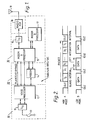
- Fig. 1 Essentially data flow through the terminal is shown in Fig. 1 and operates as follows. First assume that a voice mode has been selected. For a voice mode the handset 13 signal is digitized by means of the input/output device 11 which essentially contains an 8.0 kHz Codec and this digital information is sent to the voice processor unit 12 for rate reduction to 2400 bits per second or according to a 400 bit per second algorithm.
- the signal processing in a modem subsystem 30 can be described by two different sets of algorithm.
- the high data rate (HDR) algorithms are used when the date rates are 2400 bits per second. These algorithms are used when the frequency hopping rate is slow. These algorithms, as will be explained, are similar to those described in the above-noted co-pending application. The difference between the algorithms employed according to this invention will be described below.
- the low data rate (LDR) algorithms are used when the data rates are 400 bits per second.
- the LDR algorithms are used when the frequency hopping rate is fast.
- the modem subsystem 30 processes data separately during each frequency hop.
- the data transmitted during one frequency hop is called a packet.
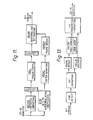
- the packet formats for the two modes of operation are shown in Fig. 2.
- a randomized PN training signal indicated by module 39 is used such that it is different for each and every frequency hop. This is done to make the system harder to jam.
- the interleave buffer 32 is coupled to the input of an 8 PSK symbol encoder which phase shift key modulates the data symbols and the output of the encoder 33 is coupled to the transmit filter 34 (TX) which serves to filter the encoded symbols.
- TX transmit filter 34
- the output of the transmit shaping filter 34 is applied to a multiplier 35 which takes the symbol output from the filter 34, which is at a sample rate of 7200 Hz, and multiplies the symbols by an exponential function, as indicated in the figure where fc equals 1800.
- the output of the multiplier is sent to a sample buffer 36 whereby the samples of buffer 36 are converted to analog signals in the digital to analog converter 37.
- This digital to analog converter 37 operates at a 7200 Hz sampling rate to provide the analog transmit signal which is the signal coupled to the radio transceiver 18 and transmitted via antenna 19.
- Fig. 3 the modules contained in Fig. 3 are implemented by means of the modem A processor 15 and the modem B processor 17 of Fig. 1. These processors, as will be further explained, operate in conjunction with one another and modem B processor 17 operates to exchange data and control signals with the modem A processor 15.
- the digital to analog converter 37 is contained in the input/output module 16 of Fig. 1 which is coupled to the modem A processor 15 and modem B processor 17.
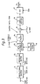
- the algorithm for the receiving function in the HDR mode is shown in Fig. 4.
- the main difference between this algorithm and that of the previous invention is the means for making the HF channel impulse response estimate, the precanceller 46 and the algorithm for calculating the equalizer coefficients and for performing equalization.
- the other algorithms in the receiver which are the same as in the previous co-pending application, are the analytic filter 43 which generates a complex form of the receive signal, the matched filter 48, which minimizes the effect of noise, the decision feedback filter 53, the de-interleave buffer 55, and the Viterbi decoder 56.
- the channel estimate algorithm uses the blocks of known PN training symbols to make an initial estimate of the HF channel impulse response and to update this estimate during the packet.
- the estimate used to calculate the matched filter and equalizer parameters for data block D k uses training blocks T 0 ..., T k (Fig. 2).
- the channel output which is observed is:
- the normal equations are a set of M linear, simultaneous equations which are solved for each v separately to give the estimate w j (v) used to calculate the matched filter 48 and equalizer parameters for data block D k .
- a Choleski decomposition algorithm is used for this solution.
- the known symbols which follow the present data symbol are the training symbols in the training block immediately following the present data block. These are cancelled by the pre-canceller 46.
- the pre-canceller 46 uses cancellation prior to the matched filter 48 and equalizer and allows the receive samples to be separated into blocks for independent processing. This, in turn, allows the use of the long division equalizer algorithm discussed below.
- the second diagram B illustrates the channel impulse response.
- the channel output, shown in C is the result of convolving this impulse response with the transmit symbols.
- the channel response causes the present data block to be spread out to cover K+M symbol intervals. In addition, it causes response due to the guard symbols to overlap the last M symbol intervals.
- the pre-canceller 46 generates this overlapping response by convolving the known guard symbols with the channel estimate and substracting it from the receive samples. This removes the effect of the guard symbols from the M overlapping symbol intervals. The receive samples beyond these overlapping smybols are zeroed. The result is a block of 3(K+M) receive samples which are passed through the matched filter 48.
- the decision feedback filter 53 is initialized with the M known training symbols immediately prior to the present data block. In this way, their intersymbol interference is cancelled from the beginning of the present data block. Thus, the receive samples due to the present block of data symbols are isolated for subsequent processing by the matched filter and equalizer.
- the coefficient of z k is the complex conjugate of the coefficient of z -k .
- C(z) is a finite polynomial with non-zero coefficients in the range of z -(m-1) to z (m+k-2) .
- C m (z) C m-1 (z) + h m z m D m ⁇ (z)
- D m (z) is an auxiliary polynomial.
- D 0 (z) M(z)
- C m (z) has only 2M-1 non-zero coefficients of which the coefficient of z 0 is unity.
- the coefficients of (z m ..., z) are constrained to be zero by the recursion.
- D m (z) also has only 2M-1 non-zero coefficients of which the coefficient of z M-1 is M M-1 and the coefficients of (z -1 , ..., z -m ) are constrained to be zero by the recursion.
- the recursions for C m (z) and D m (z) require only 4(M-1) coefficient updates per iteration.
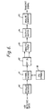
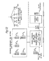
- FIG. 13 is a block diagram of the LDR receive voice algorithm.
- the bit unmapping and frame repeat functions accept as input a block of 18 bits and decodes them into parameters for two LPC frames. The first of these two frames is always a repeat frame. A modulo 2 count is maintained. If the count is zero, a block of 18 bits is read, the LPC parameters for the repeat frame are generated and the non-repeat values are stored until the next frame. If the count is one, the stored non-repeat values are used to generate the LPC parameters.
- the vector table lookup converts vector quantization values back to the LPC compatible reflection coefficients while the trellis decoder performs the same function for pitch and gain parameters. Reflection coefficients, pitch and gain parameters are then properly formatted for input to the LPC synthesis function.
Landscapes
- Engineering & Computer Science (AREA)
- Computer Networks & Wireless Communication (AREA)
- Signal Processing (AREA)
- Radar, Positioning & Navigation (AREA)
- Remote Sensing (AREA)
- Cable Transmission Systems, Equalization Of Radio And Reduction Of Echo (AREA)
- Transmission Systems Not Characterized By The Medium Used For Transmission (AREA)
- Digital Transmission Methods That Use Modulated Carrier Waves (AREA)
Claims (21)
- Hochfrequenz-Kommunikationssystem des Typs, der ein Hochfrequenzterminal verwendet, welches in einem Sendemodus ein verarbeitetes Signal senden oder in einem Empfangsmodus ein empfangenes Signal verarbeiten kann, wobei das Terminal enthält:a) ein erstes Subsystem (10) zur Sprachverarbeitung, mit einem Prozessor (12), der auf Sprachsignale anspricht, um ein gemäß einer linearen Vorhersagekodierung kodiertes Sprachsignal bei einer gegebenen Datenrate bereitzustellen, welches auf einb) Datenmodemsubsystem (20) gekoppelt wird, welches das Sprachsignal digital verschlüsselt;c) wobei das Datenmodemsubsystem (20) an ein Modemprozessorsubsystem (30) gekoppelt ist, welches in der Lage ist, das verschlüsselte Signal zu verarbeiten, um ein Frequenzspringen, eine Rückkoppelungsentzerrung, eine Zwischensymbolstörungs-Auslöschung, eine Fehlerkorrektur und eine Verschachtelung auszuführen und ein gesendetes Signal bereitzustellen, welches relativ immun ist gegenüber Störungen während des Sendemodus, wobei das Modemprozessorsubsystem (30) einen Verschachtelungspuffer (32), eine Quelle (39) für PseudorauschÜbungssignale, eine Sendefiltereinrichtung (34) und eine Digital-Analog-Wandlereinrichtung (37) aufweist,wobei das Kommunikationssystem gekennzeichnet ist durch:d) eine Faltungs-Kodiereinrichtung (31), die in dem Modemprozessorsubsystem (30) enthalten ist und auf das verschlüsselte Signal anspricht, um auf einer Ausgangsleitung der Faltungs-Kodiereinrichtung (31) ein gefaltetes Signal mit einer höheren Datenrate als das verschlüsselte Signal bereitzustellen;e) wobei der Verschachtelungspuffer (32) mit einem Eingang an die Ausgangsleitung der Faltungs-Kodiereinrichtung (31) angeschlossen ist, um das eine hohe Datenrate aufweisende Signal nach Maßgabe eines Verschachtelungsalgorithmus zu verschachteln, undf) einen Symbolkodierer (33) mit einem ersten Eingang, der auf das verschachtelte Signal anspricht, und mit einem zweiten Eingang, der an die Quelle (39) für Pseudorausch-Übungssignale angeschlossen ist, um auf einer Ausgangsleitung des Symbolkodierers (33) ein kodiertes Signal bereitzustellen, welches nach Maßgabe des Pseudorausch-Übungssignals, welches sich von jeder Sendefrequenz unterscheidet, kodiertes Signal bereitzustellen;g) wobei die Sendefiltereinrichtung (34) auf das kodierte Signal auf der Ausgangsleitung des Symbolkodierers (33) anspricht und die Bandbreite dieses Signals begrenzt;h) und die Digital-Analog-Wandlereinrichtung (37) an die Ausgangsleitung der Sendefiltereinrichtung (34) angeschlossen ist.
- Hochfrequenz-Kommunikationssystem nach Anspruch 1, dadurch gekennzeichnet, daß die Sendefiltereinrichtung (34) einen Multiplizierer (35) aufweist, um das gefilterte Signal mit einer Exponentialfunktion zu multiplizieren, und eine Puffereinrichtung (34) aufweist, um das multiplizierte Signal zu speichern, bevor es auf die Digital-Analog-Wandlereinrichtung (37) gegeben wird.
- Hochfrequenz-Kommunlationssystem nach Anspruch 1 oder 2, gekennzeichnet durch eine Entzerrereinrichtung in dem Modemprozessorsubsystem (30), die so arbeitet, daß die Entzerrung während des Empfangsmodus verbessert wird, umfassend:a) eine Kanalabschätzeinrichtung (45), die auf bekannte Pseudorausch-Übungssignalblöcke (47) anspricht, um auf eine Ausgangsleitung eine Abschätzung der empfangenen Kanalantwort bereitzustellen, wobei die Abschätzung implementiert wird durch eine Algorithmuseinrichtung für kleinste Quadrate, die auf die bekannten Pseudorausch-Übungssignalblöcke (47) anspricht, um die Abschätzung für einen gegebenen empfangenen Datenblock bereitzustellen;b) eine Vorab-Auslösch-Einrichtung (46), die auf die Abschätzung anspricht, um Daten in vorbestimmte Datenblöcke zu separieren;c) eine angepaßte Filtereinrichtung (48), die an die Vorab-Auslösch-Einrichtung (46) angeschlossen ist und auf die Datenblöcke anspricht, um die Datenblöcke bei einer gegebenen Rate abzutasten;d) eine Faltungseinrichtung (49), die an die angepaßte Filtereinrichtung (48) gekoppelt ist und mit einer Ausgangsleitung an der Einrichtung (50) angeschlossen ist, die eine Lang-Division durchführt, um auf der Ausgangsleitung der Lang-Divisionseinrichtung (50) für eine Entzerrung der Datenblöcke zu sorgen, und zwar entsprechend
wobei G(z) eine Vorwärts-Entzerrer-Übertragungsfunktion in Gestalt eines endliche Polynoms mit K von null verschiedenen Koeffizienten ist;C(z) ein endliches Polynom mit von null verschiedenen Koeffizienten ist;M(z) ein endliches Polynom in der Gestalt der Z-Transformierten der Autokorrelationsfunktion der abgeschätzten Kanalantwort ist.
 - Hochfrequenz-Kommunikationssystem nach Anspruch 3, dadurch gekennzeichnet, daß die abgeschätzte Kanalantwort beschränkt wird auf M-Symbole, wobei M(z) im Bereich von z-(M-1) bis z(M-1) 2M-1 von null verschiedene Koeffizienten aufweist.
- Hochfrequenz-Kommunikationssystem nach Anspruch 4, dadurch gekennzeichnet, daß C(z) 2m-1 von null verschiedene Koeffizienten im Bereich von z-(M-1) bis z(M+K-2) aufweist, wobei K eine Konstante ist.
- Hochfrequenz-Kommunikationssystem nach einem der Ansprüche 3 bis 5, dadurch gekennzeichnet, daß die Faltungseinrichtung (49) eine Auslöscheinrichtung aufweist, um ein Rekursions-Auslöschpolynom folgender Form bereitzustellen:


- Hochfrequenz-Kommunikationssystem nach Anspruch 6, dadurch gekennzeichnet, daß die folgenden Gleichungen ebenfalls bei der Rekursion verwendet werden:

- Hochfrequenz-Kommunikationssystem nach einem der Ansprüche 3 bis 7, dadurch gekennzeichnet, daß die Algorithmuseinrichtung für kleinste Quadrate die Kanal-Impulsantwort basierend auf Beobachtungen eines Kanalausgangssignals in Abhängigkeit der bekannten Pseudorausch-Übungssignalblöcke (47) nach Maßgabe folgender Gleichung:
 h'j' = unbekannte Kanalantwort;M = Dauer maximaler Symbolzahl der Kanalimpulsantwort;N +M = Anzahl von Pseudorausch-Übungsimpulsen in Pseudorausch-Übungsblock (47).
 - Hochfrequenz-Kommunikationssystem nach Anspruch 8, dadurch gekennzeichnet, daß es drei Sätze von Kanalimpulsantworten enthält, um die Antwort bereitzustellen nach Maßgabe von


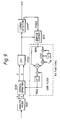
- Hochfrequenz-Kommunikationssystem nach einem der Ansprüche 1 bis 9, gekennzeichnet durcha) eine Niedrigdaten-Übertragungseinrichtung in dem Modemprozessorsubsystem (30) zum Bereitstellen einer Eingangsdatenrate von 400 Bit pro Sekunde;b) eine Kodiereinrichtung mit einer Einrichtung für die diskrete Fouriertransformation (62), die auf die Eingangsdaten anspricht und diese Daten in Form von 6-Bit-Gruppen kodiert, und mit einer Einrichtung zum Senden jeder der 6-Bit-Gruppen mit einer anderen Frequenz.
- Hochfrequenz-Kommunikationssystem nach Anspruch 10, gekennzeichnet durch eine Einrichtung (66), die im Sendemodus arbeitet, um eine Sequenz von acht bekannten Pseudorausch-Übungssignalen vor dem Absenden von Daten auszusenden.
- Hochfrequenz-Kommunikationssystem nach Anspruch 10 oder 11, gekennzeichnet durch eine Dopplerabschätzungs- und Korrektureinrichtung (70, 71, 72, 77), die im Empfangsmodus anspricht, um die bekannten Pseudorausch-Übungssignalblöcke (47) zu empfangen und daraus eine Doppler-Frequenzabschätzung bereitzustellen, die bezeichnend ist für die Qualität des Übertragungsweges.
- Hochfrequenz-Kommunikationssystem nach Anspruch 12, gekennzeichnet durcha) eine Niedrigdatenraten-Empfangseinrichtung in dem Modemprozessorsubsystem (30), mit einer Einrichtung (70) für eine diskrete Fouriertransformation, um die Amplituden von emfpangenen Tönen in mehreren Zeitschlitzen zu messen;b) wobei die Dopplerkorrektureinrichtung (71) an den Eingang der Einrichtung (70) für die diskrete Fouriertransformation angeschlossen ist, um die empfangenen Töne in den Schlitzen nach Maßgabe der Dopplerkennlinie des Übertragungsweges zu positionieren;c) eine Speichereinrichtung (74) zum Speichern der emfpangenen Töne;d) eine Datengrenzeinrichtung, die an die Speichereinrichtung (74) gekoppelt ist, um Datengrenzen für die empfangenen Töne zu bestimmen; unde) eine Decodiereinrichtung (73), die an die Dopplerabschätzungs- und Korrektureinrichtung (70, 71, 72, 77) gekoppelt ist, um ein dekodiertes Ausgangssignal bereitzustellen.
- Hochfrequenz-Kommunikationssystem nach Anspruch 12 oder 13, dadurch gekennzeichnet, daß die Einrichtung (70) für die diskrete Fouriertransformation so arbeitet, daß sie 24 Tonschlitze erzeugt, jeweils um 150 Hz beabstandet.
- Hochfrequenz-Kommunikationssystem nach einem der Ansprüche 12 oder 14, gekennzeichnet durch eine Tontabellen-Funktionseinrichtung in der Einrichtung (70) für die diskrete Fourier-Transformation, um zwei Schlitze aus 12 Schlitzen auszuwählen, die für ein Sendesignal verwendet werden.
- Hochfrequenz-Kommunikationssystem nach Anspruch 13, dadurch gekennzeichnet, daß die in der Empfangseinrichtung enthaltene Einrichtung (70) für die diskrete Fouriertransformation so arbeitet, daß sie die Amplitude der empfangenen Töne in 12 Tonschlitzen mißt.
- Hochfrequenz-Kommunikationssystem nach Anspruch 16, gekennzeichnet durch eine Symboldetektiereinrichtung (72), die auf die 12 Tonschlitze anspricht, um die empfangene Energie in bezug auf die Schlitze zu messen, und um zwei Schlitze auszuwählen, welche die größte empfangene Energie aufweisen.
- Hochfrequenz-Kommunikationssystem nach einem der Ansprüche 13 bis 17, gekennzeichnet durch eine Einrichtung zum Akkumulieren der Quadrate der empfangenen Proben innerhalb eines ersten und eines zweiten Zeitschlitzes, um eine Ausgabezeitsteuerabschätzung bereitzustellen, die bezeichnend ist für die Differenzen zwischen empfangener Energie und einer Einrichtung zum Speichern der Abschätzung, wobei dann, wenn die gespeicherte Abschätzung größer ist als eine gegebene Zahl, der erste und der zweite Zeitschlitz entsprechend geändert werden.
- Hochfrequenz-Kommunikationssystem nach einem der Ansprüche 1 bis 18, dadurch gekennzeichnet, daß das Modemprozessorsubsystem (30) ein erstes (15) und ein zweites (17) Prozessormodul enthält, wobei das erste Prozessormodul (15) mit dem Datenmodemsubsystem (20) gekoppelt ist und das zweite Prozessormodul (17) mit dem ersten Prozessormodul (15) gekoppelt ist, um mit diesem Daten und Steuerinformation auszutauschen.
- Hochfrequenz-Kommunikationssystem nach einem der Ansprüche 3 bis 19, dadurch gekennzeichnet, daß das Modemprozessorsubsystem (30) eine Analog-Digital-Wandlereinrichtung (40) enthält, die im Empfangsmodus arbeitet, um empfangene Analogdaten in digitale Daten umzuwandeln.
- Hochfrequenz-Kommunikationssystem nach Anspruch 20, dadurch gekennzeichnet, daß die Analog-Digital-Wandlereinrichtung (40) eine Abtastung bei einer Rate durchführt, die mindestens dreimal größer ist als die Rate der empfangenen Daten.
Applications Claiming Priority (2)
| Application Number | Priority Date | Filing Date | Title |
|---|---|---|---|
| US07/256,342 US4914699A (en) | 1988-10-11 | 1988-10-11 | High frequency anti-jam communication system terminal |
| US256342 | 1988-10-11 |
Publications (3)
| Publication Number | Publication Date |
|---|---|
| EP0363640A2 EP0363640A2 (de) | 1990-04-18 |
| EP0363640A3 EP0363640A3 (de) | 1992-03-18 |
| EP0363640B1 true EP0363640B1 (de) | 1997-01-15 |
Family
ID=22971890
Family Applications (1)
| Application Number | Title | Priority Date | Filing Date |
|---|---|---|---|
| EP89116457A Expired - Lifetime EP0363640B1 (de) | 1988-10-11 | 1989-09-06 | Hochfrequenzendgerät für Entstörungskommunikationssystem |
Country Status (3)
| Country | Link |
|---|---|
| US (1) | US4914699A (de) |
| EP (1) | EP0363640B1 (de) |
| DE (1) | DE68927658T2 (de) |
Cited By (2)
| Publication number | Priority date | Publication date | Assignee | Title |
|---|---|---|---|---|
| US11050443B1 (en) | 2020-09-18 | 2021-06-29 | Rockwell Collins, Inc. | Beyond line of sight waveform and line of sight waveform software-defined radio |
| US11632143B1 (en) | 2020-09-18 | 2023-04-18 | Rockwell Collins, Inc. | Multiple channel beyond line of sight waveform software-defined radio |
Families Citing this family (52)
| Publication number | Priority date | Publication date | Assignee | Title |
|---|---|---|---|---|
| US5128957A (en) * | 1990-08-10 | 1992-07-07 | Ricoh Company, Ltd. | Initial acquisition method in spread spectrum system and such system |
| JPH0777362B2 (ja) * | 1990-08-28 | 1995-08-16 | クラリオン株式会社 | スペクトラム拡散通信装置 |
| US5081643A (en) * | 1990-11-16 | 1992-01-14 | Scs Mobilecom, Inc. | Spread spectrum multipath receiver apparatus and method |
| US5390207A (en) * | 1990-11-28 | 1995-02-14 | Novatel Communications Ltd. | Pseudorandom noise ranging receiver which compensates for multipath distortion by dynamically adjusting the time delay spacing between early and late correlators |
| US5204876A (en) * | 1991-03-13 | 1993-04-20 | Motorola, Inc. | Method and apparatus for providing high data rate traffic channels in a spread spectrum communication system |
| US5265190A (en) * | 1991-05-31 | 1993-11-23 | Motorola, Inc. | CELP vocoder with efficient adaptive codebook search |
| US5345467A (en) * | 1991-07-10 | 1994-09-06 | Interdigital Technology Corp. | CDMA cellular hand-off apparatus and method |
| US5259030A (en) * | 1991-07-17 | 1993-11-02 | Harris Corporation | Antijam improvement method and apparatus |
| US5255339A (en) * | 1991-07-19 | 1993-10-19 | Motorola, Inc. | Low bit rate vocoder means and method |
| US5301274A (en) * | 1991-08-19 | 1994-04-05 | Multi-Tech Systems, Inc. | Method and apparatus for automatic balancing of modem resources |
| US5150378A (en) * | 1991-10-07 | 1992-09-22 | General Electric Company | Method and apparatus for coherent communications in non-coherent frequency-hopping system |
| US5282222A (en) * | 1992-03-31 | 1994-01-25 | Michel Fattouche | Method and apparatus for multiple access between transceivers in wireless communications using OFDM spread spectrum |
| USRE37802E1 (en) | 1992-03-31 | 2002-07-23 | Wi-Lan Inc. | Multicode direct sequence spread spectrum |
| US5233626A (en) * | 1992-05-11 | 1993-08-03 | Space Systems/Loral Inc. | Repeater diversity spread spectrum communication system |
| US5657342A (en) * | 1992-10-23 | 1997-08-12 | Olmstead; David | Adaptive data rate packet communication system |
| US5995539A (en) * | 1993-03-17 | 1999-11-30 | Miller; William J. | Method and apparatus for signal transmission and reception |
| US5367516A (en) * | 1993-03-17 | 1994-11-22 | Miller William J | Method and apparatus for signal transmission and reception |
| GB9312836D0 (en) * | 1993-06-22 | 1993-08-04 | Schlumberger Ind Ltd | Multipoint to point radiocommunications network |
| EP0744101B1 (de) * | 1994-02-10 | 1998-08-05 | International Business Machines Corporation | Verfahren und gerät für mehrbenutzer interferenz verminderung |
| US5859874A (en) * | 1994-05-09 | 1999-01-12 | Globalstar L.P. | Multipath communication system optimizer |
| US5638399A (en) * | 1994-11-15 | 1997-06-10 | Stanford Telecommunications, Inc. | Multi-beam satellite communication system with user terminal frequencies having transceivers using the same set of frequency hopping |
| KR100272472B1 (ko) * | 1995-09-19 | 2000-11-15 | 씨. 필립 채프맨 | 디지탈 프로그램가능 임계 레벨을 가진 마이크로컨트롤러 재작동 기능 |
| US5754599A (en) * | 1996-01-04 | 1998-05-19 | Motorola, Inc. | Method and apparatus for coherent channel estimation in a communication system |
| JPH09289481A (ja) * | 1996-02-20 | 1997-11-04 | Internatl Business Mach Corp <Ibm> | 無線通信機、無線通信方法及び無線通信システム |
| US6678311B2 (en) | 1996-05-28 | 2004-01-13 | Qualcomm Incorporated | High data CDMA wireless communication system using variable sized channel codes |
| US6192068B1 (en) | 1996-10-03 | 2001-02-20 | Wi-Lan Inc. | Multicode spread spectrum communications system |
| US5898728A (en) * | 1996-11-22 | 1999-04-27 | Trw Inc. | Distributed analog-digital frequency dehopping system |
| US5954839A (en) * | 1997-01-14 | 1999-09-21 | Samsung Electronics Co., Ltd. | Error protection method for multimedia data |
| IL120222A0 (en) * | 1997-02-14 | 1997-06-10 | D S P C Israel Ltd | Method and apparatus for acquiring and tracking the sampling phase of a signal |
| US6603801B1 (en) * | 1998-01-16 | 2003-08-05 | Intersil Americas Inc. | Spread spectrum transceiver for use in wireless local area network and having multipath mitigation |
| US6661996B1 (en) | 1998-07-14 | 2003-12-09 | Globalstar L.P. | Satellite communication system providing multi-gateway diversity to a mobile user terminal |
| US6584140B1 (en) * | 1999-01-22 | 2003-06-24 | Systems Information And Electronic Systems Integration Inc. | Spectrum efficient fast frequency-hopped modem with coherent demodulation |
| KR100294070B1 (ko) | 1999-06-23 | 2001-06-15 | 박태진 | 이중주파수도약 통신 시스템 및 제어방법 |
| US6760438B1 (en) * | 1999-07-01 | 2004-07-06 | Nortel Networks Limited | System and method for Viterbi decoding on encrypted data |
| MY125793A (en) * | 1999-08-12 | 2006-08-30 | Ericsson Inc | Methods for estimating doppler spreads including autocorrelation function hypotheses and related systems and receivers |
| US6850505B1 (en) * | 1999-09-01 | 2005-02-01 | Telefonaktiebolaget L M Ericsson (Publ) | Method and apparatus for Doppler frequency estimation |
| US6879640B1 (en) * | 1999-10-20 | 2005-04-12 | Broadcom Corporation | Method, apparatus and system for high-speed transmission on fiber optic channel |
| KR20010046952A (ko) * | 1999-11-16 | 2001-06-15 | 배동만 | 제밍 방지 무선 송수신 방법 |
| US7027418B2 (en) | 2001-01-25 | 2006-04-11 | Bandspeed, Inc. | Approach for selecting communications channels based on performance |
| WO2002071981A1 (en) * | 2001-03-09 | 2002-09-19 | Mobilian Corporation | Wireless receiver with anti-jamming |
| US6735264B2 (en) | 2001-08-31 | 2004-05-11 | Rainmaker Technologies, Inc. | Compensation for non-linear distortion in a modem receiver |
| US7173966B2 (en) * | 2001-08-31 | 2007-02-06 | Broadband Physics, Inc. | Compensation for non-linear distortion in a modem receiver |
| US7269233B2 (en) * | 2003-01-27 | 2007-09-11 | Novatek Microelectronics Corp. | Algorithm of bit synchronization for a digital FSK correlation receiver |
| JP2005286729A (ja) * | 2004-03-30 | 2005-10-13 | Sanyo Electric Co Ltd | 同期捕捉回路およびそれを利用した受信装置 |
| US7483671B2 (en) * | 2005-05-19 | 2009-01-27 | The United States Of America As Represented By The Secretary Of The Navy | Processor based frequency selective jamming and communications system |
| US20090103720A1 (en) * | 2005-06-07 | 2009-04-23 | Manoj Karayil Thekkoott Narayanan | Method and system for secure and anti jamming wireless communication with high spectral efficiency |
| KR100728257B1 (ko) * | 2005-10-27 | 2007-06-13 | 한국전자통신연구원 | 채널 특성 변화를 이용한 판정 궤환 등화 장치 및 그 방법 |
| US8300813B1 (en) * | 2008-02-02 | 2012-10-30 | The Boeing Company | Secure information transfer based on global position |
| US8249540B1 (en) | 2008-08-07 | 2012-08-21 | Hypres, Inc. | Two stage radio frequency interference cancellation system and method |
| US8849213B2 (en) * | 2009-01-21 | 2014-09-30 | Bandspeed, Inc. | Integrated circuit for signal analysis |
| US8447252B2 (en) * | 2009-01-21 | 2013-05-21 | Bandspeed, Inc. | Adaptive channel scanning for detection and classification of RF signals |
| US20120177086A1 (en) * | 2010-11-09 | 2012-07-12 | Space Administration | System And Apparatus Employing Programmable Transceivers |
Family Cites Families (3)
| Publication number | Priority date | Publication date | Assignee | Title |
|---|---|---|---|---|
| DE3023375C1 (de) * | 1980-06-23 | 1987-12-03 | Siemens Ag, 1000 Berlin Und 8000 Muenchen, De | |
| US4365338A (en) * | 1980-06-27 | 1982-12-21 | Harris Corporation | Technique for high rate digital transmission over a dynamic dispersive channel |
| US4761796A (en) * | 1985-01-24 | 1988-08-02 | Itt Defense Communications | High frequency spread spectrum communication system terminal |
-
1988
- 1988-10-11 US US07/256,342 patent/US4914699A/en not_active Expired - Lifetime
-
1989
- 1989-09-06 DE DE68927658T patent/DE68927658T2/de not_active Expired - Lifetime
- 1989-09-06 EP EP89116457A patent/EP0363640B1/de not_active Expired - Lifetime
Cited By (2)
| Publication number | Priority date | Publication date | Assignee | Title |
|---|---|---|---|---|
| US11050443B1 (en) | 2020-09-18 | 2021-06-29 | Rockwell Collins, Inc. | Beyond line of sight waveform and line of sight waveform software-defined radio |
| US11632143B1 (en) | 2020-09-18 | 2023-04-18 | Rockwell Collins, Inc. | Multiple channel beyond line of sight waveform software-defined radio |
Also Published As
| Publication number | Publication date |
|---|---|
| DE68927658T2 (de) | 1997-07-24 |
| EP0363640A2 (de) | 1990-04-18 |
| DE68927658D1 (de) | 1997-02-27 |
| EP0363640A3 (de) | 1992-03-18 |
| US4914699A (en) | 1990-04-03 |
Similar Documents
| Publication | Publication Date | Title |
|---|---|---|
| EP0363640B1 (de) | Hochfrequenzendgerät für Entstörungskommunikationssystem | |
| US7173966B2 (en) | Compensation for non-linear distortion in a modem receiver | |
| US4761796A (en) | High frequency spread spectrum communication system terminal | |
| EP0944977B1 (de) | Verfahren und gerät zur detektion eines digitalen symbols unter verwendung von antwortschätzungen des übertragungsmediums | |
| EP0422467B1 (de) | Hochfrequenz-Modem mit hoher Datenrate | |
| US5956624A (en) | Method and system for simultaneously broadcasting and receiving digital and analog signals | |
| JP3532556B2 (ja) | 高速データ伝送無線ローカル・エリア・ネットワーク | |
| EP1105977B1 (de) | Adaptiver empfänger für vielfachwegausbreitung in einen kodemultiplex-vielfachzugriff-kommunikationssystem | |
| KR960003835B1 (ko) | 신호 가중 시스템 | |
| CN102007703B (zh) | 通过协方差根处理的连续干扰减去的方法和设备 | |
| US6137843A (en) | Methods and apparatus for canceling adjacent channel signals in digital communications systems | |
| KR20040041590A (ko) | 모뎀 수신기에서의 비선형적인 왜곡 보상 | |
| US20050141603A1 (en) | Method and apparatus for signal transmission and reception | |
| KR100294173B1 (ko) | 통신시스템의코히런트채널추정용장치및그방법 | |
| CN111698022B (zh) | 一种基于抑制窄带多通道通信干扰的卫星通信系统 | |
| EP0566257A1 (de) | Verfahren und Einrichtung für Antennendiversity | |
| US20020006157A1 (en) | System and method for peak power reduction in spread spectrum communications systems | |
| EP0674823B1 (de) | Schätzung des mehrwegegewinns in einem empfänger | |
| SE521004C2 (sv) | Förfarande och system för demodulation av CDMA-signaler för nerlänk | |
| US20040223536A1 (en) | High data rate spread-spectrum system and method | |
| US20030236072A1 (en) | Method and apparatus for estimating a channel based on channel statistics | |
| US7577190B2 (en) | Method for prediction of a channel coefficient | |
| US6674740B1 (en) | Iterative rake receiver and corresponding reception process | |
| US6570842B1 (en) | System and apparatus for designing and producing signalling waveforms for direct-sequence code division multiple access communications | |
| Schmidt | The development of an underwater telephone for digital communication purposes |
Legal Events
| Date | Code | Title | Description |
|---|---|---|---|
| PUAI | Public reference made under article 153(3) epc to a published international application that has entered the european phase |
Free format text: ORIGINAL CODE: 0009012 |
|
| AK | Designated contracting states |
Kind code of ref document: A2 Designated state(s): DE FR GB IT |
|
| PUAL | Search report despatched |
Free format text: ORIGINAL CODE: 0009013 |
|
| AK | Designated contracting states |
Kind code of ref document: A3 Designated state(s): DE FR GB IT |
|
| 17P | Request for examination filed |
Effective date: 19920914 |
|
| 17Q | First examination report despatched |
Effective date: 19930803 |
|
| GRAG | Despatch of communication of intention to grant |
Free format text: ORIGINAL CODE: EPIDOS AGRA |
|
| GRAH | Despatch of communication of intention to grant a patent |
Free format text: ORIGINAL CODE: EPIDOS IGRA |
|
| GRAH | Despatch of communication of intention to grant a patent |
Free format text: ORIGINAL CODE: EPIDOS IGRA |
|
| GRAA | (expected) grant |
Free format text: ORIGINAL CODE: 0009210 |
|
| AK | Designated contracting states |
Kind code of ref document: B1 Designated state(s): DE FR GB IT |
|
| REF | Corresponds to: |
Ref document number: 68927658 Country of ref document: DE Date of ref document: 19970227 |
|
| ITF | It: translation for a ep patent filed | ||
| ET | Fr: translation filed | ||
| PLBE | No opposition filed within time limit |
Free format text: ORIGINAL CODE: 0009261 |
|
| STAA | Information on the status of an ep patent application or granted ep patent |
Free format text: STATUS: NO OPPOSITION FILED WITHIN TIME LIMIT |
|
| 26N | No opposition filed | ||
| REG | Reference to a national code |
Ref country code: GB Ref legal event code: IF02 |
|
| PGFP | Annual fee paid to national office [announced via postgrant information from national office to epo] |
Ref country code: FR Payment date: 20080917 Year of fee payment: 20 |
|
| PGFP | Annual fee paid to national office [announced via postgrant information from national office to epo] |
Ref country code: GB Payment date: 20080929 Year of fee payment: 20 |
|
| PGFP | Annual fee paid to national office [announced via postgrant information from national office to epo] |
Ref country code: DE Payment date: 20081031 Year of fee payment: 20 |
|
| PGFP | Annual fee paid to national office [announced via postgrant information from national office to epo] |
Ref country code: IT Payment date: 20080929 Year of fee payment: 20 |
|
| REG | Reference to a national code |
Ref country code: GB Ref legal event code: PE20 Expiry date: 20090905 |
|
| PG25 | Lapsed in a contracting state [announced via postgrant information from national office to epo] |
Ref country code: GB Free format text: LAPSE BECAUSE OF EXPIRATION OF PROTECTION Effective date: 20090905 |