EP0363651A1 - Gasspülstein - Google Patents
Gasspülstein Download PDFInfo
- Publication number
- EP0363651A1 EP0363651A1 EP89116620A EP89116620A EP0363651A1 EP 0363651 A1 EP0363651 A1 EP 0363651A1 EP 89116620 A EP89116620 A EP 89116620A EP 89116620 A EP89116620 A EP 89116620A EP 0363651 A1 EP0363651 A1 EP 0363651A1
- Authority
- EP
- European Patent Office
- Prior art keywords
- gas
- purging plug
- gas purging
- distribution space
- plug according
- Prior art date
- Legal status (The legal status is an assumption and is not a legal conclusion. Google has not performed a legal analysis and makes no representation as to the accuracy of the status listed.)
- Granted
Links
- 238000010926 purge Methods 0.000 title claims description 58
- 239000011449 brick Substances 0.000 title abstract 8
- 238000007789 sealing Methods 0.000 claims abstract description 21
- 239000002184 metal Substances 0.000 claims abstract description 14
- 229910052751 metal Inorganic materials 0.000 claims abstract description 14
- RYGMFSIKBFXOCR-UHFFFAOYSA-N Copper Chemical compound [Cu] RYGMFSIKBFXOCR-UHFFFAOYSA-N 0.000 claims description 2
- 229910052802 copper Inorganic materials 0.000 claims description 2
- 239000010949 copper Substances 0.000 claims description 2
- 238000005406 washing Methods 0.000 abstract 1
- 239000000463 material Substances 0.000 description 2
- 230000005540 biological transmission Effects 0.000 description 1
- 239000000919 ceramic Substances 0.000 description 1
- 238000010276 construction Methods 0.000 description 1
- 230000000694 effects Effects 0.000 description 1
- 230000002349 favourable effect Effects 0.000 description 1
- 238000011010 flushing procedure Methods 0.000 description 1
- 230000035699 permeability Effects 0.000 description 1
- 239000011148 porous material Substances 0.000 description 1
- 239000011819 refractory material Substances 0.000 description 1
- 239000013585 weight reducing agent Substances 0.000 description 1
Images


Classifications
-
- C—CHEMISTRY; METALLURGY
- C21—METALLURGY OF IRON
- C21C—PROCESSING OF PIG-IRON, e.g. REFINING, MANUFACTURE OF WROUGHT-IRON OR STEEL; TREATMENT IN MOLTEN STATE OF FERROUS ALLOYS
- C21C5/00—Manufacture of carbon-steel, e.g. plain mild steel, medium carbon steel or cast steel or stainless steel
- C21C5/28—Manufacture of steel in the converter
- C21C5/30—Regulating or controlling the blowing
-
- C—CHEMISTRY; METALLURGY
- C21—METALLURGY OF IRON
- C21C—PROCESSING OF PIG-IRON, e.g. REFINING, MANUFACTURE OF WROUGHT-IRON OR STEEL; TREATMENT IN MOLTEN STATE OF FERROUS ALLOYS
- C21C5/00—Manufacture of carbon-steel, e.g. plain mild steel, medium carbon steel or cast steel or stainless steel
- C21C5/28—Manufacture of steel in the converter
- C21C5/42—Constructional features of converters
- C21C5/46—Details or accessories
- C21C5/48—Bottoms or tuyéres of converters
-
- B—PERFORMING OPERATIONS; TRANSPORTING
- B22—CASTING; POWDER METALLURGY
- B22D—CASTING OF METALS; CASTING OF OTHER SUBSTANCES BY THE SAME PROCESSES OR DEVICES
- B22D1/00—Treatment of fused masses in the ladle or the supply runners before casting
- B22D1/002—Treatment with gases
- B22D1/005—Injection assemblies therefor
Definitions
- the invention relates to a gas purging plug with a gas-impermeable, refractory outer part, a gas-permeable refractory inner part arranged therein and a gas distribution space.
- gas purging stones are used in molten metal vessels.
- the gas distribution space is closed by a base plate which is permanently connected to the gas purging block and on which a gas connecting piece is formed.
- the base plate must be kept a certain distance from the permeable inner part of the gas purging plug.
- Such a gas purging plug comprises various metal parts and is complex. When replacing the gas purging plug, the bottom plate and the gas connecting piece are also replaced as integral parts thereof, without these parts being reusable in practice. This seems uneconomical.
- the object of the invention is to simplify a gas purging plug of the type mentioned.
- the above object is achieved in the case of a gas purging plug of the type mentioned at the outset in that the gas distribution space has a free opening on an end face of the outer part and in that a sealing surface is formed on the outer part, which extends around the opening and on which there is a gas connection Locking part can be struck.
- a base plate closing the gas distribution space nor a gas connecting piece is therefore provided on the gas purging plug itself. Only in operation is a closure part pressed onto the end face, which has a gas connection piece and which then sits tightly on the sealing surface of the gas flushing plug. When the gas purging plug is replaced, it is removed from the closure part and replaced. The closure part and the gas connection piece are therefore reusable.
- the construction of the gas purging plug described is considerably simplified, since no base plate with a gas connecting piece has to be welded to it.
- the transport and storage options of the gas purging plug are simplified, since no gas connection piece protrudes from it. Weight reduction is also achieved because the gas purging plug has fewer metallic parts than in the prior art.
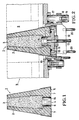
- a gas purging plug 1 consists of a gas-impermeable, conical, refractory outer part 2 and a gas-permeable, refractory inner part 3.
- the gas impermeability of the outer part 2 is achieved by means of dense, refractory material, e.g. chemically or hydraulically setting, ceramic masses with closed pores.
- the gas permeability of the inner part 3 is achieved by known, porous building blocks, which the person skilled in the art knows, for example, under the terms permeable stones, capillary rinsers, labyrinth rinsers or window washers.
- a gas distribution space 4 is formed in the outer part 2.
- the gas distribution space 4 is cylindrical and concentric in the conical gas purging plug 1.
- the gas distribution space 4 is open to the inner part 3 and has an opening 6 on the end face 5 of the outer part 2, which extends over the entire cross section of the gas distribution space 4.
- a sealing surface 7 (see FIG. 1) is formed on the end face 5 and extends in a ring around the opening 6. At the gas purging plug 1, the gas distribution space 4 is therefore open.
- the gas purging plug 1 has no gas connection piece.
- the gas purging plug 1 When using the gas purging plug 1 according to FIG. 2, it is inserted into a perforated block 8 of a base 9 of a molten metal vessel.
- the gas purging plug 1 is held on its periphery by a centering ring 10.
- a closure part 11 On the front side 5 of the gas purging plug 1, a closure part 11 is placed; in such a way that it strikes the plane of the opening 6 (see FIG. 2) on the outer part 2. This is provided with a gas connection piece 12.
- the closure part 11 engages with a protrusion 13 in the gas distribution space 4.
- the inner wall 14 of the gas distribution space 4 forms a centering guide surface for the protrusion 13.
- a sealing ring 15 is arranged, which is seated on the sealing surface 7 of the gas purging plug 1.
- the closure part 11 is fastened to a cross member 16, which is attached to pins 17 arranged on the bottom 9.
- pins 17 arranged on the bottom 9.
- a wedge 19 is driven into a transverse slot 18 and presses the closure part 11 and thus the sealing ring 15 firmly against the sealing surface 7 via the cross member 16.
- gas flows through the gas connection stub 12 into the gas distribution space 4 and through the inner part 3.
- the cross member 16 and thus the closure part 11 are lifted off the end face 5 by means of handles 20. After removal of the worn gas purging plug 1, a new gas purging plug 1 can be placed on the closure part 11 and inserted into the perforated block 8.
- the gas purging plug 1 When used in accordance with FIG. 3, the gas purging plug 1 is fastened to the closure part 11 by means of screws 21. The sealing ring 15 is thus pressed against the sealing surface 7.
- the closure part 11 is arranged on a swivel device 22.
- the swivel device 22 is actuated to replace the gas purging plug 1.
- the gas purging plug 1 is pulled out of the perforated block 8. After loosening the screws 21, the gas purging plug 1 can be replaced.
- the described gas purging plug 1 can also be fastened in the floor 9 with devices other than those described.
- the closing part 11, which closes off the gas distribution space 4 and connects to the gas supply, can in any case be easily removed from the gas purging plug 1 and, in contrast to the gas purging plug 1, can be reused.
- the outer part could also have a sheet metal jacket.
- the sealing surface 7 is then formed on this.
- a sleeve 23 is inserted into the gas distribution space 4 of the gas purging plug 1.
- This consists of a material, for example copper, which is less hard than the material of the closure part 11.
- the sleeve 23 narrows conically to the inside of the gas distribution space 4 and forms the sealing surface 7 with its inner surface.
- the sleeve 23 is supported with an edge 24 the end face 5. If the rinsing cone has a sheet metal jacket surrounding it, this sleeve 23 can be firmly connected to the sheet metal jacket.
- the substantially cylindrical projection 13 of the closure part 11 has a bevel 25 on the outside.
- the closure member 11 If the closure member 11 is pushed in the direction of arrow A perpendicular to the opening 6 with its projection 13 into the sleeve 23, then the sleeve 23 is pressed so that it bears sealingly on the inner wall 14 of the gas distribution space 4 and on the projection 13. It is favorable in comparison to the exemplary embodiment according to FIG. 4 that the pressure acting on the sealing surface 7 does not have to be applied by the force which holds the gas purging plug 1 and the closure part 11 together perpendicular to the plane of the opening 6 during operation. This improves the sealing effect without a particularly high force being required to maintain the stop of the closure part 11 on the gas purging plug 1.
- the sleeve 23 is part of the gas purging plug 1 and is replaced with this.
- the gas purging plug 1 need not have a sheet metal jacket. However, it can at least on its circumference, on the area where the centering ring 10 rests, with a sheet metal jacket be provided, which can extend to the top of the cone.
- the power transmission from the centering ring 10 to the gas purging plug 1 is improved in such a way that the outer part 2 is less prone to breakage.
- the partial sheet metal jacket can be designed so that it takes over the holding function of the centering ring 10, so that the centering ring 10 can be dispensed with as a separate component. It is also possible to connect this partial sheet metal jacket directly to the closure part 11. This can be done, for example, by a bayonet-type closure. The screws reaching into the gas purging stones 1 can then be omitted.
Landscapes
- Engineering & Computer Science (AREA)
- Chemical & Material Sciences (AREA)
- Manufacturing & Machinery (AREA)
- Materials Engineering (AREA)
- Metallurgy (AREA)
- Organic Chemistry (AREA)
- Mechanical Engineering (AREA)
- Treatment Of Steel In Its Molten State (AREA)
- Casting Support Devices, Ladles, And Melt Control Thereby (AREA)
- Carbon Steel Or Casting Steel Manufacturing (AREA)
- Manufacture And Refinement Of Metals (AREA)
- Crystals, And After-Treatments Of Crystals (AREA)
- Cleaning Or Drying Semiconductors (AREA)
- Glass Compositions (AREA)
- Furnace Charging Or Discharging (AREA)
- Filling Or Discharging Of Gas Storage Vessels (AREA)
- Percussion Or Vibration Massage (AREA)
Abstract
Description
- Die Erfindung betrifft einen Gasspülstein mit einem gasundurchlässigen, feuerfesten Außenteil, einem darin angeordneten, gasdurchlässigen feuerfesten Innenteil und einem Gasverteilungsraum. Derartige Gasspülsteine werden bei Metallschmelzengefäßen verwendet.
- Verschiedene Gasspülsteine sind beispielsweise in der DE-PS 36 23 609 beschrieben.
- Bei Gasspülsteinen ist der Gasverteilungsraum durch eine mit dem Gasspülstein dauerhaft fest verbundenen Bodenplatte verschlossen, an der ein Gasanschlußstutzen ausgebildet ist. Zur Bildung des Gasverteilungsraumes muß die Bodenplatte einem bestimmten Abstand vom permeablen Innenteil des Gasspülsteins gehalten sein. Ein solcher Gasspülstein umfaßt verschiedene Metallteile und ist aufwendig. Beim Austausch des Gasspülsteines werden als dessen integrale Bestandteile auch die Bodenplatte und der Gasanschlußstutzen mitausgewechselt, ohne daß diese Teile in der Praxis wiederverwendbar sind. Dies erscheint unwirtschaftlich.
- Aufgabe der Erfindung ist es, einen Gasspülstein der eingangs genannten Art zu vereinfachen.
- Erfindungsgemäß ist obige Aufgabe bei einem Gasspülstein der eingangs genannten Art dadurch gelöst, daß der Gasverteilungsraum an einer Stirnseite des Außenteils eine freie Öffnung aufweist und daß an dem Außenteil eine Dichtfläche ausgebildet ist, die sich um die Öffnung erstreckt und an der ein mit einem Gasanschluß versehenes Verschlußteil anschlagbar ist.
- Am Gasspülstein selbst ist also weder eine den Gasverteilungsraum verschließende Bodenplatte noch ein Gasanschlußstutzen vorgesehen. Erst im Betrieb wird auf die Stirnseite ein Verschlußteil angedrückt, das einen Gasanschlußstutzen aufweist und das dann dicht auf der Dichtfläche des Gasspülsteins aufsitzt. Beim Auswechseln des Gasspülsteins wird dieser von dem Verschlußteil abgenommen und ausgetauscht. Das Verschlußteil und der Gasanschlußstutzen sind also wiederverwendbar.
- Der Aufbau des beschriebenen Gasspülsteins ist wesentlich vereinfacht, da an ihn keine Bodenplatte mit Gasanschlußstutzen angeschweißt werden muß. Außerdem sind die Transport- und Lagermöglichkeiten des Gasspülsteins vereinfacht, da an ihm kein Gasanschlußstutzen vorsteht. Es ist auch eine Gewichtsreduzierung erreicht, da der Gasspülstein weniger metallische Teile als beim Stand der Technik aufweist.
- Vorteilhafte Ausgestaltungen der Erfindung ergeben sich aus den Unteransprüchen und der folgenden Beschreibung. In der Zeichnung zeigen:
- Figur 1 einen Gasspülstein,
- Figur 2 den Gasspülstein im Einsatz,
- Figur 3 ein weiteres Einsatzbeispiel des Gasspülsteins, und
- Figur 4 ein weiteres Ausführungsbeispiel des Gasspülsteines.
- Ein Gasspülstein 1 besteht aus einem gasundurchlässigen, kegelförmigen, feuerfesten Außenteil 2 und einem gasdurchlässigen, feuerfesten Innenteil 3. Die Gasundurchlässigkeit des Außenteils 2 wird durch dichtes, feuerfestes Material erreicht, wie z.B. chemisch oder hydraulisch abbindende, keramische Massen mit geschlossenen Poren. Die Gasdurchlässigkeit des Innenteils 3 wird durch an sich bekannte, poröse Bausteine erreicht, die der Fachmann beispielsweise unter den Begriffen permeable Steine, Kapillarspüler, Labyrinthspüler oder Scheibenspüler kennt.
- Ein Gasverteilungsraum 4 ist im Außenteil 2 ausgebildet. Der Gasverteilungsraum 4 ist zylindrisch und konzentrisch im kegelförmigen Gasspülstein 1.
- Der Gasverteilungsraum 4 ist zum Innenteil 3 hin offen und weist an der Stirnseite 5 des Außenteils 2 eine Öffnung 6 auf, die sich über den gesamten Querschnitt des Gasverteilraumes 4 erstreckt. An der Stirnseite 5 ist eine Dichtfläche 7 (vgl. Figur 1) ausgebildet, die sich ringförmig um die Öffnung 6 erstreckt. Am Gasspülstein 1 ist der Gasverteilungsraum 4 also offen. Der Gasspülstein 1 weist keinen Gasanschlußstutzen auf.
- Bei der Verwendung des Gasspülsteins 1 nach Figur 2 ist dieser in einen Lochstein 8 eines Bodens 9 eines Metallschmelzengefäßes eingesetzt. Der Gasspülstein 1 ist an seinem Umfang von einem Zentrierring 10 gehalten. Auf die Stirnseite 5 des Gasspülsteines 1 ist ein Verschlußteil 11 aufgesetzt; und zwar so, daß es zur Ebene der Öffnung 6 (siehe Figur 2) am Außenteil 2 anschlägt. Dieses ist mit einem Gasanschlußstutzen 12 versehen. Das Verschlußteil 11 greift mit einem Vorsprung 13 in den Gasverteilungsraum 4. Die Innenwand 14 des Gasverteilungsraumes 4 bildet dabei eine zentrierende Führungsfläche für den Vorsprung 13.
- An dem Verschlußteil 11 ist ein Dichtring 15 angeordnet, der auf der Dichtfläche 7 des Gasspülsteins 1 aufsitzt.
- Das Verschlußteil 11 ist an einer Traverse 16 befestigt, die auf am Boden 9 angeordnete Zapfen 17 aufgesteckt ist. In Figur 2 ist nur einer der Zapfen 17 gezeigt. In einen Querschlitz 18 ist ein Keil 19 eingetrieben, der über die Traverse 16 das Verschlußteil 11 und damit den Dichtring 15 fest gegen die Dichtfläche 7 preßt.
- Im Betrieb strömt durch den Gasanschlußstutzen 12 Gas in den Gasverteilungsraum 4 und durch das Innenteil 3.
- Ist der Gasspülstein 1 verschlissen, dann wird mittels Handgriffen 20 die Traverse 16 und damit das Verschlußteil 11 von der Stirnseite 5 abgehoben. Nach Entfernen des verschlissenen Gasspülsteines 1 läßt sich auf das Verschlußteil 11 ein neuer Gasspülstein 1 aufsetzen und in den Lochstein 8 einführen.
- Beim Einsatz entsprechend Figur 3 ist der Gasspülstein 1 mittels Schrauben 21 an dem Verschlußteil 11 befestigt. Der Dichtring 15 ist damit gegen die Dichtfläche 7 gepreßt.
- Das Verschlußteil 11 ist an einer Schwenkvorrichtung 22 angeordnet. Zum Auswechseln des Gasspülsteins 1 wird die Schwenkvorrichtung 22 betätigt. Dadurch wird der Gasspülstein 1 aus dem Lochstein 8 herausgezogen. Nach dem Lösen der Schrauben 21 läßt sich der Gasspülstein 1 austauschen.
- Der beschriebene Gasspülstein 1 kann auch mit anderen als den beschriebenen Einrichtungen im Boden 9 befestigt werden. Das den Gasverteilungsraum 4 abschließende und an die Gaszufuhr anschließende Verschlußteil 11 ist in jedem Fall leicht vom Gasspülstein 1 abzunehmen und im Gegensatz zum Gasspülstein 1 wiederverwendbar.
- Das Außenteil könnte auch einen Blechmantel aufweisen. Die Dichtfläche 7 ist dann an diesem ausgebildet.
- Beim Ausführungsbeispiel nach Figur 4 ist in den Gasverteilungsraum 4 des Gasspülsteins 1 eine Hülse 23 eingesetzt. Diese besteht aus einem Material, beispielsweise Kupfer, das weniger hart ist als das Material des Verschlußteils 11. Die Hülse 23 verengt sich konisch zum Innern des Gasverteilungsraumes 4 und bildet mit ihrer Innenfläche die Dichtfläche 7. Die Hülse 23 stützt sich mit einem Rand 24 an der Stirnseite 5 ab. Diese Hülse 23 kann, falls der Spülkegel einen ihn umschließenden Blechmantel aufweist, mit dem Blechmantel fest verbunden sein.
- Der im wesentlichen zylindrische Vorsprung 13 des Verschlußteils 11 weist außen eine Abschrägung 25 auf.
- Wird das Verschlußteil 11 in Richtung des Pfeiles A senkrecht zur Öffnung 6 mit seinem Vorsprung 13 in die Hülse 23 eingeschoben, dann wird die Hülse 23 verpreßt, so daß sie dichtend an der Innenwand 14 des Gasverteilungsraumes 4 und an dem Vorsprung 13 anliegt. Günstig dabei ist im Vergleich zum Ausführungsbeispiel nach Figur 4, daß der auf die Dichtfläche 7 wirkende Druck nicht durch die Kraft aufgebracht werden muß, der im Betrieb den Gasspülstein 1 und das Verschlußteil 11 senkrecht zur Ebene der Öffnung 6 zusammenhält. Dies verbessert die Dichtwirkung, ohne daß eine besonders hohe Kraft zum Aufrechterhalten des Anschlags des Verschlußteils 11 am Gasspülstein 1 nötig ist.
- Die Hülse 23 ist Bestandteil des Gasspülsteins 1 und wird mit diesem ausgewechselt.
- Der Gasspülstein 1 braucht keinen Blechmantel aufzuweisen. Er kann jedoch wenigstens an seinem Umfang, an dem Bereich, an dem der Zentrierring 10 anliegt, mit einem Blechmantel versehen sein, der sich bis zur Kegelspitze erstrecken kann. Die Kraftübertragung vom Zentrierring 10 auf den Gasspülstein 1 ist dadurch in der Weise verbessert, daß das Außenteil 2 weniger bruchgefährdet ist. Der Teil-Blechmantel kann dabei so gestaltet sein, daß er die Haltefunktion des Zentrierrings 10 übernimmt, so daß der Zentrierring 10 als separates Bauteil entfallen kann. Es ist auch möglich, diesen Teil-Blechmantel direkt mit dem Verschlußteil 11 zu verbinden. Dies kann beispielsweise durch einen bajonettartigen Verschluß erfolgen. Die in den Gasspülsteinen 1 greifenden Schrauben können dann entfallen.
Claims (11)
dadurch gekennzeichnet,
daß der Gasverteilungsraum (4) an einer Stirnseite (5) des Außenteils (2) eine freie Öffnung (6) aufweist und daß an dem Außenteil (2) eine Dichtfläche (7) ausgebildet ist, die sich um die Öffnung (6) erstreckt und an der ein mit einem Gasanschluß (12) versehenes Verschlußteil (11) anschlagbar ist.
dadurch gekennzeichnet,
daß die Öffnung (6) sich über den gesamten Querschnitt des Gasverteilungsraumes (4) erstreckt.
dadurch gekennzeichnet,
daß der Gasverteilungsraum (4) im Gasspülstein (1) zylindrisch und konzentrisch ausgebildet ist.
dadurch gekennzeichnet,
daß die Dichtfläche (7) an der Stirnseite (5) ausgebildet ist.
dadurch gekennzeichnet,
daß die Dichtfläche (7) an der Innenwand (14) des Gasverteilungsraumes (4) ausgebildet ist.
dadurch gekennzeichnet,
daß als Dichtfläche eine metallische Hülse (23) in dem Gasverteilungsraum (4) im Außenteil (2) eingesetzt ist.
dadurch gekennzeichnet,
daß die Hülse (23) aus Kupfer besteht.
dadurch gekennzeichnet,
daß die Innenwand (14) des Gasverteilungsraumes (4) eine Führungsfläche für einen Vorsprung (13) des auf die Stirnseite (5) aufsetzbaren Verschlußteiles (11) bildet.
dadurch gekennzeichnet,
daß die Dichtfläche (7) zur dichtenden Anlage eines Dichtringes (15) des an der Stirnseite (5) lösbar anschlagbaren Verschlußteiles (11) vorgesehen ist.
dadurch gekennzeichnet,
daß das Verschlußteil (11) senkrecht zur Öffnung (6) an der Stirnseite (5) anschlagbar ist.
dadurch gekennzeichnet,
daß der Gasspülstein (1) einen Teil-Blechmantel aufweist, der mit dem Verschlußteil (11) lösbar verbindbar ist.
Applications Claiming Priority (2)
| Application Number | Priority Date | Filing Date | Title |
|---|---|---|---|
| DE3833502 | 1988-10-01 | ||
| DE3833502A DE3833502A1 (de) | 1988-10-01 | 1988-10-01 | Gasspuelstein |
Publications (2)
| Publication Number | Publication Date |
|---|---|
| EP0363651A1 true EP0363651A1 (de) | 1990-04-18 |
| EP0363651B1 EP0363651B1 (de) | 1996-11-20 |
Family
ID=6364231
Family Applications (1)
| Application Number | Title | Priority Date | Filing Date |
|---|---|---|---|
| EP89116620A Expired - Lifetime EP0363651B1 (de) | 1988-10-01 | 1989-09-08 | Gasspülstein |
Country Status (10)
| Country | Link |
|---|---|
| US (1) | US4978108A (de) |
| EP (1) | EP0363651B1 (de) |
| JP (1) | JPH02118012A (de) |
| KR (1) | KR0138105B1 (de) |
| CN (1) | CN1019026B (de) |
| AT (1) | ATE145433T1 (de) |
| CA (1) | CA1337499C (de) |
| DE (2) | DE3833502A1 (de) |
| ES (1) | ES2095834T3 (de) |
| ZA (1) | ZA896796B (de) |
Cited By (4)
| Publication number | Priority date | Publication date | Assignee | Title |
|---|---|---|---|---|
| EP0458040A3 (en) * | 1990-04-24 | 1991-12-11 | Didier-Werke Ag | Gas purging assembly with a perforated brick and a gas purging brick |
| EP0521371A1 (de) * | 1991-06-28 | 1993-01-07 | Veitsch-Radex Aktiengesellschaft für feuerfeste Erzeugnisse | Gasspülstein |
| EP0609562A1 (de) * | 1993-02-04 | 1994-08-10 | BECK u. KALTHEUNER, FEUERFESTE ERZEUGNISSE GmbH & CO. KG | Keramischer Spülstein für Stahlbehandlungspfannen |
| EP1078702A1 (de) * | 1999-08-27 | 2001-02-28 | MANNESMANN Aktiengesellschaft | Gasspüleinrichtung für ein metallurgisches Gefäss |
Families Citing this family (14)
| Publication number | Priority date | Publication date | Assignee | Title |
|---|---|---|---|---|
| DE4022949C1 (de) * | 1990-07-19 | 1991-07-11 | Radex-Heraklith Industriebeteiligungs Ag, Wien, At | |
| DE4025956A1 (de) * | 1990-08-16 | 1992-02-20 | Didier Werke Ag | Feuerfeste fuellung eines ringspaltes bei einem metallurgischen gefaess |
| EP0502256A3 (en) * | 1991-03-06 | 1992-12-09 | Beck U. Kaltheuner, Feuerfeste Erzeugnissegmbh & Co. Kg | Gas bubbling device for the treatment of steel in a ladle |
| DE4136552A1 (de) * | 1991-11-06 | 1993-05-13 | Kortec Ag | Dueseneinrichtung zum einleiten von medien in eine schmelze und verfahren zum betrieb dieser dueseneinrichtung |
| CN1059324C (zh) * | 1994-06-03 | 2000-12-13 | 赵学瑞 | 筋骨复原膏 |
| DE19954918C2 (de) * | 1999-11-16 | 2001-09-20 | Veitsch Radex Gmbh Wien | Feuerfester keramischer Gasspülstein |
| EP1243361A1 (de) * | 2001-03-19 | 2002-09-25 | Vesuvius Crucible Company | Vorrichtung zum Einleiten von Gasen in eine Metallschmelze |
| DE10259434B3 (de) * | 2002-12-19 | 2004-08-26 | Refractory Intellectual Property Gmbh & Co.Kg | Gasspüleinrichtung für metallurgische Schmelzgefäße |
| DE10360827B3 (de) * | 2003-12-23 | 2005-06-09 | Refractory Intellectual Property Gmbh & Co. Kg | Halteeinrichtung für Spülelemente |
| JP2011194457A (ja) * | 2010-03-23 | 2011-10-06 | Kurosaki Harima Corp | ガス吹き込み用プラグの設置構造 |
| HUE029621T2 (en) | 2012-08-27 | 2017-03-28 | Refractory Intellectual Property Gmbh & Co Kg | Gas inlet element with associated gas supply line |
| PT2711107E (pt) * | 2012-09-20 | 2014-11-18 | Refractory Intellectual Prop | Tampão em cerâmica refractária para purgar gás e processo para fabricar o referido tampão para purgar gás |
| RS54558B1 (sr) * | 2014-01-09 | 2016-06-30 | Refractory Intellectual Property Gmbh & Co. Kg | Element za prečišćavanje gasom i odgovarajući element za priključivanje gasa |
| EP4622755A1 (de) | 2022-11-25 | 2025-10-01 | Vesuvius Group, S.A. | Gasspülstein und system zur leichten installation des gasspülsteins in einem metallurgischen gefäss |
Citations (3)
| Publication number | Priority date | Publication date | Assignee | Title |
|---|---|---|---|---|
| DE1726983U (de) * | 1956-05-29 | 1956-07-26 | Aluminiumwerke Nuernberg G M B | Vorrichtung zur gaseinfuehrung in metallische schmelzen. |
| GB1027537A (en) * | 1964-03-14 | 1966-04-27 | British Cast Iron Res Ass | Improvements in ladles for treatment of molten metals |
| GB1421793A (en) * | 1973-06-20 | 1976-01-21 | Electricity Council | Injectors for injecting gas into molten metal |
Family Cites Families (9)
| Publication number | Priority date | Publication date | Assignee | Title |
|---|---|---|---|---|
| US3541604A (en) * | 1967-02-01 | 1970-11-17 | Nippon Steel Corp | Gas insufflating means for a molten metal refining container |
| SE328967B (de) * | 1969-02-20 | 1970-09-28 | Asea Ab | |
| JPS5931702U (ja) * | 1982-08-24 | 1984-02-28 | 市光工業株式会社 | 車輌用補助灯 |
| AT376455B (de) * | 1982-10-06 | 1984-11-26 | Oesterr Amerikan Magnesit | Metallurgischer ofen oder metallurgisches gefaess |
| WO1985001068A1 (fr) * | 1983-08-20 | 1985-03-14 | Brohltal-Deumag Ag Für Feuerfeste Erzeugnisse; | Appareil d'extraction pour une pierre refractaire d'injection de gaz |
| AT383617B (de) * | 1984-09-18 | 1987-07-27 | Oesterr Amerikan Magnesit | Gasspuelstein fuer metallurgische oefen und gefaesse |
| DE3538498A1 (de) * | 1985-10-30 | 1987-05-07 | Didier Werke Ag | Einduesvorrichtung fuer metallurgische gefaesse |
| GB8703717D0 (en) * | 1987-02-18 | 1987-03-25 | Injectall Ltd | Injecting gas into metal melts |
| DE3716920A1 (de) * | 1987-05-20 | 1988-12-08 | Steuler Industriewerke Gmbh | Gasspuelsystem mit gasdurchbruchssicherung |
-
1988
- 1988-10-01 DE DE3833502A patent/DE3833502A1/de active Granted
-
1989
- 1989-09-05 ZA ZA896796A patent/ZA896796B/xx unknown
- 1989-09-08 EP EP89116620A patent/EP0363651B1/de not_active Expired - Lifetime
- 1989-09-08 ES ES89116620T patent/ES2095834T3/es not_active Expired - Lifetime
- 1989-09-08 DE DE58909750T patent/DE58909750D1/de not_active Expired - Fee Related
- 1989-09-08 AT AT89116620T patent/ATE145433T1/de not_active IP Right Cessation
- 1989-09-22 KR KR1019890013644A patent/KR0138105B1/ko not_active Expired - Fee Related
- 1989-09-26 JP JP1248266A patent/JPH02118012A/ja active Pending
- 1989-09-28 CN CN89107557A patent/CN1019026B/zh not_active Expired
- 1989-09-28 US US07/413,671 patent/US4978108A/en not_active Expired - Fee Related
- 1989-09-29 CA CA000614582A patent/CA1337499C/en not_active Expired - Fee Related
Patent Citations (3)
| Publication number | Priority date | Publication date | Assignee | Title |
|---|---|---|---|---|
| DE1726983U (de) * | 1956-05-29 | 1956-07-26 | Aluminiumwerke Nuernberg G M B | Vorrichtung zur gaseinfuehrung in metallische schmelzen. |
| GB1027537A (en) * | 1964-03-14 | 1966-04-27 | British Cast Iron Res Ass | Improvements in ladles for treatment of molten metals |
| GB1421793A (en) * | 1973-06-20 | 1976-01-21 | Electricity Council | Injectors for injecting gas into molten metal |
Cited By (6)
| Publication number | Priority date | Publication date | Assignee | Title |
|---|---|---|---|---|
| EP0458040A3 (en) * | 1990-04-24 | 1991-12-11 | Didier-Werke Ag | Gas purging assembly with a perforated brick and a gas purging brick |
| EP0521371A1 (de) * | 1991-06-28 | 1993-01-07 | Veitsch-Radex Aktiengesellschaft für feuerfeste Erzeugnisse | Gasspülstein |
| EP0609562A1 (de) * | 1993-02-04 | 1994-08-10 | BECK u. KALTHEUNER, FEUERFESTE ERZEUGNISSE GmbH & CO. KG | Keramischer Spülstein für Stahlbehandlungspfannen |
| EP1078702A1 (de) * | 1999-08-27 | 2001-02-28 | MANNESMANN Aktiengesellschaft | Gasspüleinrichtung für ein metallurgisches Gefäss |
| DE19941639A1 (de) * | 1999-08-27 | 2001-03-08 | Mannesmann Ag | Gasspüleinrichtung für ein metallurgisches Gefäß |
| DE19941639C2 (de) * | 1999-08-27 | 2001-09-13 | Mannesmann Ag | Gasspüleinrichtung für ein metallurgisches Gefäß |
Also Published As
| Publication number | Publication date |
|---|---|
| ZA896796B (en) | 1990-06-27 |
| KR0138105B1 (ko) | 1998-07-15 |
| DE3833502C2 (de) | 1990-10-04 |
| ATE145433T1 (de) | 1996-12-15 |
| EP0363651B1 (de) | 1996-11-20 |
| DE58909750D1 (de) | 1997-01-02 |
| CN1019026B (zh) | 1992-11-11 |
| CN1041616A (zh) | 1990-04-25 |
| JPH02118012A (ja) | 1990-05-02 |
| DE3833502A1 (de) | 1990-04-05 |
| KR900006535A (ko) | 1990-05-08 |
| US4978108A (en) | 1990-12-18 |
| CA1337499C (en) | 1995-11-07 |
| ES2095834T3 (es) | 1997-03-01 |
Similar Documents
| Publication | Publication Date | Title |
|---|---|---|
| DE3833502C2 (de) | ||
| EP0364723B1 (de) | Gasspüleinrichtung | |
| DE3634448C2 (de) | ||
| DE4308286A1 (de) | Verfahren und Vorrichtung zum Abreinigen von mit staubförmigen Partikeln zugesetzten Filtern einer Filteranlage | |
| DE3433123C2 (de) | Blasstein für metallurgische Pfannen und Verfahren zu seinem Einfügen in die Zustellung | |
| EP0544997B1 (de) | Einrichtung zum Halten eines Stopfens und Stopfen | |
| EP0364724A1 (de) | Gasspüleinrichtung | |
| DE4012952C1 (de) | ||
| DE3311617C1 (de) | Verfahren und Einrichtung zum Spuelen einer Metallschmelze,insbesondere von Stahl,in einer Giesspfanne | |
| EP0169290A2 (de) | Vorrichtung für den Einsatz in der Entgasung von geschmolzenem Metall | |
| LU87458A1 (de) | Spuelstein | |
| EP0858515B1 (de) | Wechselvorrichtung für eine blaslanze | |
| DE2921722C2 (de) | Schleusenrohr für anstückelbare Lichtbogenelektroden bei vakuummetallurgischen Anlagen | |
| DE3808450C2 (de) | ||
| EP0310665A1 (de) | Einrichtung zum thermischen entgraten von stücken | |
| DE9412304U1 (de) | Rohrdichtkissen mit Positioniereinrichtung | |
| DE8501727U1 (de) | Reinigungsgerät mit einem als Aufnahmegefäß des Reinigungsmittels ausgebildeten Handgriff | |
| DE19838311A1 (de) | Zusatzeinrichtung für eine Vorrichtung zum Reinigen metallischer Fässer, insbesondere Bierfässer | |
| DE3500866A1 (de) | Schiebeverschluss fuer den ausguss an metallurgischen gefaessen, insbesondere stahlgiesspfannen | |
| EP0358115A2 (de) | Zweigeteilter Endstein | |
| DE3805276C2 (de) | Filteranordnung für radioaktive Stoffe | |
| DE466142C (de) | Vorrichtung zum Auftragen mineralischer Schwaerze auf Gussformen | |
| DE1246001B (de) | Vakuumbehaelter zum Entgasen von Metall-, insbesondere von Eisen- und Stahlschmelzen | |
| DE19542368C2 (de) | Mundstück für eine Stopfmaschine | |
| CH662963A5 (en) | Method and device for purging a metal melt in a casting ladle |
Legal Events
| Date | Code | Title | Description |
|---|---|---|---|
| PUAI | Public reference made under article 153(3) epc to a published international application that has entered the european phase |
Free format text: ORIGINAL CODE: 0009012 |
|
| 17P | Request for examination filed |
Effective date: 19890927 |
|
| AK | Designated contracting states |
Kind code of ref document: A1 Designated state(s): AT BE CH DE ES FR GB IT LI LU NL SE |
|
| 17Q | First examination report despatched |
Effective date: 19920220 |
|
| GRAH | Despatch of communication of intention to grant a patent |
Free format text: ORIGINAL CODE: EPIDOS IGRA |
|
| GRAH | Despatch of communication of intention to grant a patent |
Free format text: ORIGINAL CODE: EPIDOS IGRA |
|
| GRAA | (expected) grant |
Free format text: ORIGINAL CODE: 0009210 |
|
| AK | Designated contracting states |
Kind code of ref document: B1 Designated state(s): AT BE CH DE ES FR GB IT LI LU NL SE |
|
| PG25 | Lapsed in a contracting state [announced via postgrant information from national office to epo] |
Ref country code: FR Free format text: THE PATENT HAS BEEN ANNULLED BY A DECISION OF A NATIONAL AUTHORITY Effective date: 19961120 |
|
| REF | Corresponds to: |
Ref document number: 145433 Country of ref document: AT Date of ref document: 19961215 Kind code of ref document: T |
|
| ITF | It: translation for a ep patent filed | ||
| REF | Corresponds to: |
Ref document number: 58909750 Country of ref document: DE Date of ref document: 19970102 |
|
| ET | Fr: translation filed | ||
| GBT | Gb: translation of ep patent filed (gb section 77(6)(a)/1977) |
Effective date: 19961210 |
|
| REG | Reference to a national code |
Ref country code: ES Ref legal event code: FG2A Ref document number: 2095834 Country of ref document: ES Kind code of ref document: T3 |
|
| PG25 | Lapsed in a contracting state [announced via postgrant information from national office to epo] |
Ref country code: GB Free format text: LAPSE BECAUSE OF NON-PAYMENT OF DUE FEES Effective date: 19970908 Ref country code: AT Free format text: LAPSE BECAUSE OF NON-PAYMENT OF DUE FEES Effective date: 19970908 |
|
| PG25 | Lapsed in a contracting state [announced via postgrant information from national office to epo] |
Ref country code: SE Free format text: LAPSE BECAUSE OF NON-PAYMENT OF DUE FEES Effective date: 19970909 Ref country code: ES Free format text: LAPSE BECAUSE OF NON-PAYMENT OF DUE FEES Effective date: 19970909 |
|
| PLBE | No opposition filed within time limit |
Free format text: ORIGINAL CODE: 0009261 |
|
| STAA | Information on the status of an ep patent application or granted ep patent |
Free format text: STATUS: NO OPPOSITION FILED WITHIN TIME LIMIT |
|
| PG25 | Lapsed in a contracting state [announced via postgrant information from national office to epo] |
Ref country code: LU Free format text: LAPSE BECAUSE OF NON-PAYMENT OF DUE FEES Effective date: 19970930 Ref country code: BE Free format text: LAPSE BECAUSE OF NON-PAYMENT OF DUE FEES Effective date: 19970930 |
|
| 26N | No opposition filed | ||
| BERE | Be: lapsed |
Owner name: DIDIER-WERKE A.G. Effective date: 19970930 |
|
| GBPC | Gb: european patent ceased through non-payment of renewal fee |
Effective date: 19970908 |
|
| PG25 | Lapsed in a contracting state [announced via postgrant information from national office to epo] |
Ref country code: DE Free format text: LAPSE BECAUSE OF NON-PAYMENT OF DUE FEES Effective date: 19980603 |
|
| EUG | Se: european patent has lapsed |
Ref document number: 89116620.9 |
|
| REG | Reference to a national code |
Ref country code: FR Ref legal event code: ST |
|
| PGFP | Annual fee paid to national office [announced via postgrant information from national office to epo] |
Ref country code: CH Payment date: 19980824 Year of fee payment: 10 |
|
| PGFP | Annual fee paid to national office [announced via postgrant information from national office to epo] |
Ref country code: NL Payment date: 19980827 Year of fee payment: 10 |
|
| PG25 | Lapsed in a contracting state [announced via postgrant information from national office to epo] |
Ref country code: LI Free format text: LAPSE BECAUSE OF NON-PAYMENT OF DUE FEES Effective date: 19990930 Ref country code: CH Free format text: LAPSE BECAUSE OF NON-PAYMENT OF DUE FEES Effective date: 19990930 |
|
| PG25 | Lapsed in a contracting state [announced via postgrant information from national office to epo] |
Ref country code: NL Free format text: LAPSE BECAUSE OF NON-PAYMENT OF DUE FEES Effective date: 20000401 |
|
| REG | Reference to a national code |
Ref country code: CH Ref legal event code: PL |
|
| NLV4 | Nl: lapsed or anulled due to non-payment of the annual fee |
Effective date: 20000401 |
|
| REG | Reference to a national code |
Ref country code: ES Ref legal event code: FD2A Effective date: 19981013 |
|
| PG25 | Lapsed in a contracting state [announced via postgrant information from national office to epo] |
Ref country code: IT Free format text: LAPSE BECAUSE OF NON-PAYMENT OF DUE FEES;WARNING: LAPSES OF ITALIAN PATENTS WITH EFFECTIVE DATE BEFORE 2007 MAY HAVE OCCURRED AT ANY TIME BEFORE 2007. THE CORRECT EFFECTIVE DATE MAY BE DIFFERENT FROM THE ONE RECORDED. Effective date: 20050908 |