EP0363680B1 - Procédé pour la transmission de données - Google Patents
Procédé pour la transmission de données Download PDFInfo
- Publication number
- EP0363680B1 EP0363680B1 EP89117193A EP89117193A EP0363680B1 EP 0363680 B1 EP0363680 B1 EP 0363680B1 EP 89117193 A EP89117193 A EP 89117193A EP 89117193 A EP89117193 A EP 89117193A EP 0363680 B1 EP0363680 B1 EP 0363680B1
- Authority
- EP
- European Patent Office
- Prior art keywords
- data
- mod
- loop current
- called
- modem
- Prior art date
- Legal status (The legal status is an assumption and is not a legal conclusion. Google has not performed a legal analysis and makes no representation as to the accuracy of the status listed.)
- Expired - Lifetime
Links
- 238000000034 method Methods 0.000 title claims abstract description 20
- 230000005540 biological transmission Effects 0.000 title claims description 13
- 238000001514 detection method Methods 0.000 claims description 9
- JAPJOLBDXOXSKE-WQICJITCSA-N (2s)-2-[[(2s)-2-[[(e)-3-(furan-2-yl)prop-2-enoyl]amino]-3-phenylpropanoyl]amino]-3-phenylpropanoic acid Chemical compound C([C@@H](C(=O)O)NC(=O)[C@H](CC=1C=CC=CC=1)NC(=O)\C=C\C=1OC=CC=1)C1=CC=CC=C1 JAPJOLBDXOXSKE-WQICJITCSA-N 0.000 claims description 5
- 230000004044 response Effects 0.000 abstract description 15
- 238000010586 diagram Methods 0.000 description 3
- 238000011156 evaluation Methods 0.000 description 3
- 230000000717 retained effect Effects 0.000 description 2
- 230000006870 function Effects 0.000 description 1
- 238000002955 isolation Methods 0.000 description 1
- 238000012544 monitoring process Methods 0.000 description 1
- 238000004321 preservation Methods 0.000 description 1
Images


Classifications
-
- H—ELECTRICITY
- H04—ELECTRIC COMMUNICATION TECHNIQUE
- H04M—TELEPHONIC COMMUNICATION
- H04M11/00—Telephonic communication systems specially adapted for combination with other electrical systems
- H04M11/06—Simultaneous speech and data transmission, e.g. telegraphic transmission over the same conductors
Definitions
- the invention relates to a method for transmitting data between subscribers of the public switched telephone network, in each of which at least one telephone set, one data modem with a circuit for ringing voltage detection, with a sound transmitter and with a sound receiver, and a data terminal are connected to the telephone switched network with which the switch from telephony to data transmission by the data modem is carried out either automatically or by pressing a data key, with which the data modem is used to determine whether the subscriber is the caller or the called party before switching through the data transmission and with which manual operation after When the data key is actuated, a distinction is made between "called” state and "calling" state, whether or not a ringing voltage was recognized by the data modem when the loop current was used (JP-A-62 216 460).
- CCITT recommendation V.25 stipulates that the called subscriber sends a data response tone. On the one hand, this serves to remove echo blocks on the transmission path. On the other hand, the reception of the Data response tones to the calling subscriber that the called subscriber is equipped with a data modem and that data exchange with this subscriber is therefore possible. The calling subscriber or his data modem must also be able to recognize the end of the data response tone, since only then can data be sent. According to CCITT, the data response tone should last 3.3 ⁇ 0.7 s. It is said to have a frequency of 2100 Hz.
- the respective data modem Before starting the data transmission, the respective data modem must therefore be able to recognize whether "its" subscriber has been called (called state) or is itself the caller (called state) so that it can cause the data response tone to be sent as the called party.
- state For duplex operation, knowledge of the call status or call status is also required for the selection of the channel position, since according to CCITT, the data of the calling subscriber is generally transmitted to the called subscriber via channel 1, while channel 2 is used for transmission in the opposite direction.
- CCITT recommendation V.25 No detailed information is given in the CCITT recommendations for manual operation. For example, the participants of two manual stations should make an appointment.
- DE-B-1 275 093 describes a method for automatic channel selection in two-channel data modems.
- a channel switching relay is assigned to each participant of these data modems.
- As a criterion for the selection of the transmission channel only the own dialing impulses are used for the calling subscriber and only the incoming callsign for the called subscriber.
- the changeover with channel assignment is effected by a flip-flop.
- a circuit with different timers is used to distinguish between the call state and the call state, which evaluate whether the data response tone has arrived within a time that can be set on one of the timers or not.
- the timer starts when the data modem is switched on to the telephone line.
- a measuring unit and a decision unit are provided with which the status of the telephone handset on the one hand and the presence of a call on the other hand are determined. Depending on the signals from these units, the data modem is either switched to the "called" state or to the "calling" state.
- the aim of the invention is to further develop the method described at the beginning in such a way that the establishment of a connection by subscribers to the public switched telephone network is achieved more reliably and more quickly in accordance with the recommendations of the CCITT.
- the presence of a call voltage is recognized by the data modem if the own subscriber is from another subscriber is called. If loop current then flows because the receiver of the telephone set has been lifted from the subscriber, the data modem recognizes from the sequence - first ringing voltage, then loop current - that his subscriber is being called. After pressing the data key, he then causes the data response tone to be released to cancel the echo locks and switches the data terminal to channel 2 in duplex mode as a called subscriber. no ringing voltage, but loop current - that his subscriber is the one calling. No data response tone is sent.
- the data terminal In duplex mode, the data terminal is switched to channel 1 after pressing the data key.
- the transmission of the data response tone and possibly the channel selection are therefore independent of any timers in this method.
- the criterion as to whether or not the data response tone arrives within a certain time is irrelevant for the recognition of the called state or the calling end state. Rather, this finding is made before the data response tone is sent and is responsible for its sending.
- the data modems are equipped with a memory, which can also be connected to the existing microprocessor to form a microcontroller.
- the respective sequence, whether ringing voltage was present when the loop current started or not, is stored in the memory until the loop current flows again. It is not necessary to specifically delete the stored information.
- the data transmission can, for example, be interrupted by the data terminal if, for example, two subscribers with manual stations for mutual information want to talk to each other.
- the channel position in duplex mode is also retained and the data exchange can be continued without delay after hanging up the telephone sets.
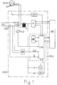
- Fig. 1 in a block diagram the facilities available at a participant.
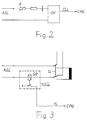
- Fig. 2 shows a circuit for ringing voltage detection.
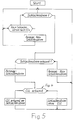
- Fig. 3 shows a circuit for loop current monitoring.
- FIG. 4 to 6 flow diagrams of functional sequences when performing the method according to the invention.
- the individual stations can be equipped for automatic or manual operation. Before establishing a data connection, the data modem must recognize in each station whether its station is calling itself or whether it is being called so that the data response tone is transmitted and the associated data terminal is connected to the correct channel - channel 1 or 2 - if necessary.
- A calls A A calls M A is called by A.
- A is called by M.
- M calls M M calls A M is called by M.
- M is called by A.
- the present method therefore does not apply to data exchange between automatic stations, but only if at least one of the two stations is a manual station.
- FIG. 1 shows a data modem MOD surrounded by a dash-dotted line, which is a data transmission device.
- a data terminal DEE is connected to the MOD via corresponding lines.
- the subscriber also has a FAPP telephone set with a DT data key that does not belong to the MOD.
- the heart of the MOD is the microprocessor CPU (Central Processing Unit), which controls all processes.
- a memory called RAM, is connected to the CPU, in which functions can be stored, such as telephone numbers of certain subscribers in the telephone dialing network.
- the RAM can be combined with the CPU and other inputs and outputs of the CPU to form an MCU (Micro Controller Unit).
- the MOD also includes a sound transmitter TS and a sound receiver TE, both of which are connected to the CPU.
- a loop current monitor ISÜ for detecting whether the loop current IS is flowing and a ringing voltage detection RSE from which an incoming call CLL originates are part of the MOD.
- ISÜ and RSE are also connected to the CPU. This also applies to the data key recognition DTE, which is used to monitor whether the DT is pressed, and for the actual modem M to transmit the data from the DEE to the connection line ASL of the telephone dialing network.
- the MOD is connected to the ASL by a relay labeled LU, which actuates the changeover switch U.
- the FAPP When the MOD is connected to the ASL, the FAPP is disconnected.
- the switch U In Fig. 1, the switch U is in the position in which the FAPP is connected to the ASL. The MOD is then not connected to the ASL.
- the MOD of each manual station is equipped with an RSE, by means of which a frequency and amplitude evaluation of the ringing voltage signals is carried out.
- This circuit can be referred to as an electronic circuit with bandpass characteristics. It has a timer to bridge the pauses between the ringing voltage signals. This bridging is necessary so that when the loop current IS is inserted in one of the breaks, the participant of the MOD is not is incorrectly identified as the caller.
- a retriggerable monoflop can be used as the timing element, which holds the information for about 6 seconds.
- the RSE in a simple embodiment.
- the ringing voltage is caused by another subscriber to be transmitted via the ASL and detected, for example, by the resistor R.
- the RSE includes an optocoupler OK for electrical isolation, from which the signal CLL corresponding to an existing ringing voltage originates and is sent to the CPU.
- FIG. 3 is a simple embodiment of a current sensitive relay SR, which responds as soon as a loop current IS flows. The corresponding signal is sent to the CPU.
- Fig. 4 shows the sequence in the ringing voltage detection with a frequency evaluation.
- An electronic circuit with bandpass characteristics is used for this.
- the lower limit of the bandpass is 18 Hz and the upper limit is 60 Hz. If such a signal is detected, the timer is reset and the CLL signal is output. No signal is recognized in the pauses between the ringing voltage signals. However, the pauses are bridged by the timer for 6 seconds (6000 ms). Since the next signal normally comes after 4 seconds, the left path (yes) in FIG. 4 remains. Only when no new signal comes after more than 6000 ms, the signal CLL is not passed on. So it didn't become one Call voltage recognized.
- the loop current detection according to FIG. 5 is also to be understood.
- the end result here says that the MOD recognizes the "called" state according to the left box at the bottom, since the ringing voltage (yes) was recognized before the loop current was applied. After the right box at the bottom, however, the "calling" state is recognized, since no (no) call voltage was recognized before the loop current was applied.
- Fig. 6 shows the sequence when the MOD is connected to the ASL by actuating the DT.
- the bottom left is correct if the participant has been called. It then sends the answer tone to release the echo locks.
- the bottom right is correct if the subscriber is the caller himself.
- the subscriber picks up the receiver of his FAPP, as a result of which the loop current IS flows.
- the sequence (sequence) - application of the ringing voltage and subsequent loop current - is recognized and saved by the MOD.
- the operator presses Participants use their DT for data exchange.
- the MOD knows that his station has been called. He now sends out the data response tone and connects his DEE to channel 2 if necessary. The data exchange can then be started.
- the storage of the information explained above is retained in the MOD as long as the telephone connection exists.
- the MOD automatically sends a data response tone again and again if the data exchange is to be resumed, without having to recognize again whether the station has been called or calls itself.
- the participant then presses his DT and thereby activates the TS.
- the data exchange can be interrupted by the DEE, for example, if the two users of two manual stations want to make phone calls to each other for information purposes.
Landscapes
- Engineering & Computer Science (AREA)
- Computer Networks & Wireless Communication (AREA)
- Signal Processing (AREA)
- Telephonic Communication Services (AREA)
- Prepayment Telephone Systems (AREA)
- Data Exchanges In Wide-Area Networks (AREA)
- Amplifiers (AREA)
- Static Random-Access Memory (AREA)
- Signal Processing Not Specific To The Method Of Recording And Reproducing (AREA)
- Selective Calling Equipment (AREA)
- Photoreceptors In Electrophotography (AREA)
- Communication Control (AREA)
Claims (1)
- Procédé pour transmettre des données entre des abonnés du réseau téléphonique public, procédé dans le cas duquel on raccorde respectivement au moins un appareil téléphonique (FAPP),un modem de données (MOD) avec un circut de reconnaissance d'une tension d'appel (RSE), avec un émetteur de tonalité (TS) et avec un récepteur de tonalité (TE) ainsi qu'un appareil terminal de données (DEE) au réseau téléphonique automatique, avec lequel la transformation de conversations téléphoniques en transmission de données par le modem de données (MOD) est opéré soit automatiquement soit par actionnement manuel , avec lequel au moyen du modem de données (MOD) on détermine avant la mise en circuit de la transmission de données chez chaque abonné, s'il est celui qui appelle ou s'il est celui qui est appelé et avec lequel, en cas de fonctionnement manuel, après l'actionnement de la touche d'échange de données (DT) on distingue de cette façon entre la situation "d'appelé" et la situation "d'appelant", selon que le modem de données (MOD) a détecté ou pas lors de l'établissement du courant de boucle (IS) une tension d'appel, procédé caractérisé en ce que :- l'on utilise un modem de données (MOD) avec un circuit qui sert à court-circuiter les pauses d'appel et- l'on garde en mémoire la séquence détectée par le modem (MOD) qui sert à savoir si il y a eu ou pas une tension d'appel lors de l'établissement du courant de boucle (IS), jusqu'a ce que le courant de boucle (IS) soit interrompu ou jusqu'a ce que le courant de boucle soit rétabli.
Applications Claiming Priority (2)
| Application Number | Priority Date | Filing Date | Title |
|---|---|---|---|
| DE3834515 | 1988-10-11 | ||
| DE3834515 | 1988-10-11 |
Publications (3)
| Publication Number | Publication Date |
|---|---|
| EP0363680A2 EP0363680A2 (fr) | 1990-04-18 |
| EP0363680A3 EP0363680A3 (fr) | 1992-06-10 |
| EP0363680B1 true EP0363680B1 (fr) | 1995-11-08 |
Family
ID=6364817
Family Applications (1)
| Application Number | Title | Priority Date | Filing Date |
|---|---|---|---|
| EP89117193A Expired - Lifetime EP0363680B1 (fr) | 1988-10-11 | 1989-09-16 | Procédé pour la transmission de données |
Country Status (5)
| Country | Link |
|---|---|
| US (1) | US5038373A (fr) |
| EP (1) | EP0363680B1 (fr) |
| AT (1) | ATE130147T1 (fr) |
| DE (1) | DE58909486D1 (fr) |
| FI (1) | FI894393A7 (fr) |
Families Citing this family (2)
| Publication number | Priority date | Publication date | Assignee | Title |
|---|---|---|---|---|
| ES2048083B1 (es) * | 1992-01-08 | 1996-10-16 | Girons Jorge Moix | Aparato para la captura y transmision automatizada de datos por red telefonica conmutada. |
| JP5485390B2 (ja) * | 2010-06-15 | 2014-05-07 | パナソニック株式会社 | スイッチング電源装置および半導体装置 |
Family Cites Families (3)
| Publication number | Priority date | Publication date | Assignee | Title |
|---|---|---|---|---|
| US4304970A (en) * | 1979-11-14 | 1981-12-08 | Gte Products Corp. | Telephone status monitor apparatus |
| US4578796A (en) * | 1983-11-03 | 1986-03-25 | Bell Telephone Laboratories, Incorporated | Programmable multiple type data set |
| US4805213A (en) * | 1987-02-13 | 1989-02-14 | Unison Technologies, Inc. | Ring detector |
-
1989
- 1989-09-16 AT AT89117193T patent/ATE130147T1/de not_active IP Right Cessation
- 1989-09-16 DE DE58909486T patent/DE58909486D1/de not_active Expired - Fee Related
- 1989-09-16 EP EP89117193A patent/EP0363680B1/fr not_active Expired - Lifetime
- 1989-09-18 FI FI894393A patent/FI894393A7/fi not_active IP Right Cessation
- 1989-09-22 US US07/411,420 patent/US5038373A/en not_active Expired - Fee Related
Also Published As
| Publication number | Publication date |
|---|---|
| US5038373A (en) | 1991-08-06 |
| FI894393A7 (fi) | 1990-04-12 |
| EP0363680A2 (fr) | 1990-04-18 |
| FI894393A0 (fi) | 1989-09-18 |
| EP0363680A3 (fr) | 1992-06-10 |
| DE58909486D1 (de) | 1995-12-14 |
| ATE130147T1 (de) | 1995-11-15 |
Similar Documents
| Publication | Publication Date | Title |
|---|---|---|
| DE3786590T2 (de) | Funktelefonsystem mit gemeinsamem Signalisierungskanal. | |
| EP0116296B1 (fr) | Méthode et dispositif pour signalisation entre des appareils visiophoniques pendant une communication téléphonique existante | |
| DE69320855T2 (de) | Videokonferenzeinrichtung | |
| DE3888583T2 (de) | Verfahren zur steuerung der verbindung kabelfreier fernsprecher. | |
| DE2028511A1 (fr) | ||
| DE3785823T2 (de) | Schnurloses Telefonsystem. | |
| EP0473773B1 (fr) | Dispositif de commande pour appareil d'abonne pour la commutation automatique du type de communication | |
| DE69028830T2 (de) | Schnurloser Telefonapparat | |
| EP0363680B1 (fr) | Procédé pour la transmission de données | |
| DE1955296A1 (de) | Fernsprechvermittlungsanlage mit Anruf-Wartet-Sonderbedienung | |
| DE1762884C3 (de) | Schaltungsanordnung zur Bereitstellung von Sonderdiensten in Fernmelde-, insbesondere Fernsprechvermittlungsanlagen | |
| DE1273596B (de) | Fernsprechkonferenzanlage | |
| DE3782265T2 (de) | Vielfach-zugriff-kommunikationssystem mit schaltungseinrichtung zur schleifenpruefung fuer das durchschalten von lokalen verbindungen. | |
| DE19935870A1 (de) | Verfahren zum Herstellen einer Verbindung zwischen zwei Informationsübertragungsterminals und Terminal zum Durchführen des Verfahrens | |
| DE3885803T3 (de) | Schnurloses Telefonsystem. | |
| DE3930893A1 (de) | Verfahren zur uebertragung von daten | |
| DE2826323B1 (de) | Schaltungsanordnung zum UEbertragen von Signalen zwischen einer Datenuebertragungseinheit und einem Datenendgeraet | |
| DE9014465U1 (de) | Weichenvorrichtung für Ferngespräche | |
| DE869085C (de) | Schaltungsanordnung fuer Fernsprechanlagen mit Waehlerbetrieb | |
| DE68922763T2 (de) | Telefonapparat und Steuerungsverfahren dafür. | |
| DE69119279T2 (de) | Geteiltes Faksimile-Telefon-Kommunikationsgerät | |
| DE2161989A1 (de) | Fernsprechvermittlungsanlage für Gespräche mit erforderlicher Bedienungshilfe | |
| DE3410145A1 (de) | Schaltungsanordnung zum anschalten einer zusatzeinrichtung an eine fernsprechleitung | |
| EP0164312A1 (fr) | Procédé pour la programmation à distance d'au moins un indicatif dans une station radio et station radio pour l'application du procédé | |
| DE69624832T2 (de) | Verfahren und vorrichtung zur abhebesignalisierung zwischen telefonen oder zusätzen auf demselben kreis |
Legal Events
| Date | Code | Title | Description |
|---|---|---|---|
| PUAI | Public reference made under article 153(3) epc to a published international application that has entered the european phase |
Free format text: ORIGINAL CODE: 0009012 |
|
| AK | Designated contracting states |
Kind code of ref document: A2 Designated state(s): AT CH DE FR GB LI NL |
|
| RAP1 | Party data changed (applicant data changed or rights of an application transferred) |
Owner name: KE KOMMUNIKATIONS-ELEKTRONIK GMBH & CO. |
|
| PUAL | Search report despatched |
Free format text: ORIGINAL CODE: 0009013 |
|
| AK | Designated contracting states |
Kind code of ref document: A3 Designated state(s): AT CH DE FR GB LI NL |
|
| 17P | Request for examination filed |
Effective date: 19920429 |
|
| 17Q | First examination report despatched |
Effective date: 19940422 |
|
| GRAA | (expected) grant |
Free format text: ORIGINAL CODE: 0009210 |
|
| AK | Designated contracting states |
Kind code of ref document: B1 Designated state(s): AT CH DE FR GB LI NL |
|
| REF | Corresponds to: |
Ref document number: 130147 Country of ref document: AT Date of ref document: 19951115 Kind code of ref document: T |
|
| REF | Corresponds to: |
Ref document number: 58909486 Country of ref document: DE Date of ref document: 19951214 |
|
| GBT | Gb: translation of ep patent filed (gb section 77(6)(a)/1977) |
Effective date: 19951222 |
|
| REG | Reference to a national code |
Ref country code: CH Ref legal event code: NV Representative=s name: PATENTANWAELTE GEORG ROEMPLER UND ALDO ROEMPLER |
|
| ET | Fr: translation filed | ||
| PLBE | No opposition filed within time limit |
Free format text: ORIGINAL CODE: 0009261 |
|
| STAA | Information on the status of an ep patent application or granted ep patent |
Free format text: STATUS: NO OPPOSITION FILED WITHIN TIME LIMIT |
|
| PGFP | Annual fee paid to national office [announced via postgrant information from national office to epo] |
Ref country code: NL Payment date: 19960916 Year of fee payment: 8 |
|
| 26N | No opposition filed | ||
| PG25 | Lapsed in a contracting state [announced via postgrant information from national office to epo] |
Ref country code: NL Free format text: LAPSE BECAUSE OF NON-PAYMENT OF DUE FEES Effective date: 19980401 |
|
| NLV4 | Nl: lapsed or anulled due to non-payment of the annual fee |
Effective date: 19980401 |
|
| PGFP | Annual fee paid to national office [announced via postgrant information from national office to epo] |
Ref country code: GB Payment date: 20010814 Year of fee payment: 13 |
|
| PGFP | Annual fee paid to national office [announced via postgrant information from national office to epo] |
Ref country code: CH Payment date: 20010816 Year of fee payment: 13 |
|
| PGFP | Annual fee paid to national office [announced via postgrant information from national office to epo] |
Ref country code: AT Payment date: 20010824 Year of fee payment: 13 |
|
| PGFP | Annual fee paid to national office [announced via postgrant information from national office to epo] |
Ref country code: DE Payment date: 20010903 Year of fee payment: 13 |
|
| PGFP | Annual fee paid to national office [announced via postgrant information from national office to epo] |
Ref country code: FR Payment date: 20010904 Year of fee payment: 13 |
|
| REG | Reference to a national code |
Ref country code: GB Ref legal event code: IF02 |
|
| PG25 | Lapsed in a contracting state [announced via postgrant information from national office to epo] |
Ref country code: GB Free format text: LAPSE BECAUSE OF NON-PAYMENT OF DUE FEES Effective date: 20020916 Ref country code: AT Free format text: LAPSE BECAUSE OF NON-PAYMENT OF DUE FEES Effective date: 20020916 |
|
| PG25 | Lapsed in a contracting state [announced via postgrant information from national office to epo] |
Ref country code: LI Free format text: LAPSE BECAUSE OF NON-PAYMENT OF DUE FEES Effective date: 20020930 Ref country code: CH Free format text: LAPSE BECAUSE OF NON-PAYMENT OF DUE FEES Effective date: 20020930 |
|
| PG25 | Lapsed in a contracting state [announced via postgrant information from national office to epo] |
Ref country code: DE Free format text: LAPSE BECAUSE OF NON-PAYMENT OF DUE FEES Effective date: 20030401 |
|
| GBPC | Gb: european patent ceased through non-payment of renewal fee |
Effective date: 20020916 |
|
| REG | Reference to a national code |
Ref country code: CH Ref legal event code: PL |
|
| PG25 | Lapsed in a contracting state [announced via postgrant information from national office to epo] |
Ref country code: FR Free format text: LAPSE BECAUSE OF NON-PAYMENT OF DUE FEES Effective date: 20030603 |
|
| REG | Reference to a national code |
Ref country code: FR Ref legal event code: ST |