EP0363709A2 - Device for use at seals of planar construction parts for drainage, parcelling and production of a toothing between seal and layer applied thereto, for bridges, parking ramps, reservoirs, ground water protection plants and the like - Google Patents
Device for use at seals of planar construction parts for drainage, parcelling and production of a toothing between seal and layer applied thereto, for bridges, parking ramps, reservoirs, ground water protection plants and the like Download PDFInfo
- Publication number
- EP0363709A2 EP0363709A2 EP89117566A EP89117566A EP0363709A2 EP 0363709 A2 EP0363709 A2 EP 0363709A2 EP 89117566 A EP89117566 A EP 89117566A EP 89117566 A EP89117566 A EP 89117566A EP 0363709 A2 EP0363709 A2 EP 0363709A2
- Authority
- EP
- European Patent Office
- Prior art keywords
- drainage
- seal
- layer
- parcelling
- toothing
- Prior art date
- Legal status (The legal status is an assumption and is not a legal conclusion. Google has not performed a legal analysis and makes no representation as to the accuracy of the status listed.)
- Withdrawn
Links
- 239000003673 groundwater Substances 0.000 title claims description 3
- 238000010276 construction Methods 0.000 title abstract description 8
- 238000004519 manufacturing process Methods 0.000 title description 2
- 239000010410 layer Substances 0.000 claims abstract description 22
- 239000011241 protective layer Substances 0.000 claims abstract description 8
- 238000007789 sealing Methods 0.000 claims description 10
- 229910000831 Steel Inorganic materials 0.000 claims description 7
- 239000010959 steel Substances 0.000 claims description 7
- 239000004567 concrete Substances 0.000 claims description 6
- 239000011230 binding agent Substances 0.000 claims description 3
- 239000013521 mastic Substances 0.000 claims description 3
- XLYOFNOQVPJJNP-UHFFFAOYSA-N water Substances O XLYOFNOQVPJJNP-UHFFFAOYSA-N 0.000 claims description 3
- 238000009434 installation Methods 0.000 claims description 2
- 239000004033 plastic Substances 0.000 claims description 2
- 239000011440 grout Substances 0.000 claims 1
- 230000002093 peripheral effect Effects 0.000 claims 1
- 229920003002 synthetic resin Polymers 0.000 claims 1
- 239000000057 synthetic resin Substances 0.000 claims 1
- 238000000926 separation method Methods 0.000 abstract description 2
- 230000005540 biological transmission Effects 0.000 abstract 1
- 230000015572 biosynthetic process Effects 0.000 description 6
- 238000004873 anchoring Methods 0.000 description 2
- 239000010426 asphalt Substances 0.000 description 2
- 238000007667 floating Methods 0.000 description 2
- 230000002028 premature Effects 0.000 description 2
- 238000003860 storage Methods 0.000 description 2
- 239000011384 asphalt concrete Substances 0.000 description 1
- 239000011248 coating agent Substances 0.000 description 1
- 238000000576 coating method Methods 0.000 description 1
- 208000018459 dissociative disease Diseases 0.000 description 1
- 230000000694 effects Effects 0.000 description 1
- 239000003822 epoxy resin Substances 0.000 description 1
- 230000006870 function Effects 0.000 description 1
- 239000011521 glass Substances 0.000 description 1
- 230000003993 interaction Effects 0.000 description 1
- 239000007788 liquid Substances 0.000 description 1
- 238000000034 method Methods 0.000 description 1
- 230000005012 migration Effects 0.000 description 1
- 238000013508 migration Methods 0.000 description 1
- 229920000647 polyepoxide Polymers 0.000 description 1
- 238000004382 potting Methods 0.000 description 1
- 230000008569 process Effects 0.000 description 1
- 230000009993 protective function Effects 0.000 description 1
- 238000005086 pumping Methods 0.000 description 1
- 230000008439 repair process Effects 0.000 description 1
Images


Classifications
-
- E—FIXED CONSTRUCTIONS
- E01—CONSTRUCTION OF ROADS, RAILWAYS, OR BRIDGES
- E01D—CONSTRUCTION OF BRIDGES, ELEVATED ROADWAYS OR VIADUCTS; ASSEMBLY OF BRIDGES
- E01D19/00—Structural or constructional details of bridges
- E01D19/08—Damp-proof or other insulating layers; Drainage arrangements or devices ; Bridge deck surfacings
- E01D19/086—Drainage arrangements or devices
-
- E—FIXED CONSTRUCTIONS
- E01—CONSTRUCTION OF ROADS, RAILWAYS, OR BRIDGES
- E01D—CONSTRUCTION OF BRIDGES, ELEVATED ROADWAYS OR VIADUCTS; ASSEMBLY OF BRIDGES
- E01D19/00—Structural or constructional details of bridges
- E01D19/08—Damp-proof or other insulating layers; Drainage arrangements or devices ; Bridge deck surfacings
- E01D19/083—Waterproofing of bridge decks; Other insulations for bridges, e.g. thermal ; Bridge deck surfacings
-
- E—FIXED CONSTRUCTIONS
- E02—HYDRAULIC ENGINEERING; FOUNDATIONS; SOIL SHIFTING
- E02B—HYDRAULIC ENGINEERING
- E02B3/00—Engineering works in connection with control or use of streams, rivers, coasts, or other marine sites; Sealings or joints for engineering works in general
- E02B3/16—Sealings or joints
Definitions
- the invention relates to a device according to the preamble of claim 1.
- the planned installations are intended to enable clear assignment of tasks in the interaction of the individual layers and to eliminate the risk of undesired crack formation by dividing large areas into individual plots.
Landscapes
- Engineering & Computer Science (AREA)
- Structural Engineering (AREA)
- Civil Engineering (AREA)
- General Engineering & Computer Science (AREA)
- Architecture (AREA)
- Environmental & Geological Engineering (AREA)
- Ocean & Marine Engineering (AREA)
- Mechanical Engineering (AREA)
- Sealing With Elastic Sealing Lips (AREA)
- Bridges Or Land Bridges (AREA)
- Road Paving Structures (AREA)
Abstract
Description
Die Erfindung betrifft eine Vorrichtung nach dem Oberbegriff des Anspruches 1.The invention relates to a device according to the preamble of
Die vorgesehenen Einbauten sollen eine eindeutige Zuweisung von Aufgaben im Zusammenwirken der einzelnen Schichten ermöglichen und durch die Aufteilung großer Flächen in einzelne Parzellen das Risiko ungewollter Rißbildungen ausschalten.The planned installations are intended to enable clear assignment of tasks in the interaction of the individual layers and to eliminate the risk of undesired crack formation by dividing large areas into individual plots.
Bei den derzeitig angewendeten Abdichtungs- und Belagskonstruktionen ist eine feste Verklebung aller Schichten zwangsläufig gegeben. Diese Bauweise setzt jedoch voraus, daß vor allem die Schutzschicht auf der Abdichtung unter Verkehr ihre Aufgabe, nämlich ihre Schutzfunktion, beibehält. Dies ist aber nicht immer der Fall. Sie wird infolge von Spannungen aus Temperaturwechsel und Verformungen unter der Verkehrsbelastung rissig. Diese Risse übertragen sich bei dieser Bauweise zwangsläufig auf die Abdichtung. Da sie meißt das erträgliche Maß für die Abdichtung überschreiten, kommt es an ihr zu vorzeitigen Schäden. Auch ist bei dieser Bauweise eine Blasenbildung in den Belagsschichten durch Fremdeinschlüsse und deren Wachstum durch Temperaturschwankunge nicht zu verhindern. Die Einlage eines Glasvlieses wurde auch seither schon angewendet, doch führte die nur punktweise vorgesehene Entwässerung zur Pfützenbildung bei mangelhafter Gefälleauslegung auf der Abdichtungsoberfläche und förderte damit eine gewisse Pumpwirkung bei Verkehrsbelastung, die dann zur vorzeitigen Ermüdung des Belages und zu seinem Aufbrechen führte. Auch die allseitig umlaufende Fugenausbildung in der Gußasphaltschutzschicht begünstigt diesen Vorgang. Bei der damit verbundenen schwimmenden Lagerung dieser Schicht, wanderte diese zur tiefen Seite ab und quetschte den relativ welchen Fugenverguß aus. Mit dieser Wanderung der Schutzschicht wurde aber bereits eine erste Überbeanspruchung der Abdichtung unvermeidbar, da ja eine feste Verklebung vorlag. Auf die Ausbildung der umlaufenden Vergußfuge kann aber bei dieser Bauweise nicht verzichtet werden, da einsickerndes Wasser im Randbereich keine Entwässerungsmöglichkeit hat, also der Fugenverguß eine Dichtungsfunktion übernehmen muß. Diese Aufgabe kann er auf Dauer nur unzulänglich erfüllen.With the sealing and covering constructions currently used, all layers must be firmly bonded. However, this design presupposes that the protective layer on the seal under traffic maintains its task, namely its protective function. However, this is not always the case. It becomes cracked due to tensions from temperature changes and deformations under the traffic load. With this type of construction, these cracks are inevitably transferred to the seal. Since it exceeds the tolerable level for the seal, it will cause premature damage. With this type of construction, the formation of bubbles in the covering layers due to foreign inclusions and their growth due to temperature fluctuations cannot be prevented. The insert of a glass fleece has also been used since then, but the only point-provided drainage caused puddles when the slope was poorly laid out on the sealing surface and thus promoted a certain pumping effect during traffic loads, which then led to premature fatigue of the covering and its break-up. The all-round joint formation in the mastic asphalt protection layer also favors this process. With the associated floating storage of this layer, it migrated to the deep side and squeezed out the relatively which joint potting. With this migration of the protective layer, however, there was already a first overuse sealing was unavoidable, since there was a firm bond. With this construction, the formation of the encircling grouting joint cannot be dispensed with, since infiltrating water in the edge area has no possibility of drainage, that is to say the grouting of the joints must take on a sealing function. In the long run, he can only fulfill this task insufficiently.
Mit den erfindungsgemäßen Einbauten lassen sich diese vorgenannten Nachteile der seitherigen Bauweisen vermeiden. Es erfolgt eine klare Trennung der Aufgaben eines jeden, im Gesamtsystem vorhandenen Bauteile. Vor allem die Dränung aus Einkornbeton unter den Schrammborden bzw. entlang der Formstahlprofile, die das eingesickerte Wasser auf kürzestem Wege sammeln und abführen und eine Pfützenbildung verhindern, lassen eine wesentlich längere Lebensdauer der Abdichtung erwarten.Dazu trägt aber auch die mit der Parzellierung erreichbare feste Einspannung der Schutzschicht zwischen die Formstahlprofile bei, weil jetzt die Randfugenausbildung, die eine "schwimmende Lagerung" der Schutzschicht bewirkt entfallen kann. Durch die feste Arretierung der Schutzschicht einerseits und die Trennung von Abdichtung und Belag andererseits, wird die Anforderung an die Risseüberbrückungsfähigkeit der Abdichtung ( derzeit 2 mm, auch bei Minusgraden ) geringer, da die Beanspruchung aus möglichen Rissen im Belagsaufbau entfällt. Die Abdichtungen können zu Gunsten anderer Eigenschaften verbessert werden. Dies ist vor allem bei der immer mehr zur Anwendung kommenden Flüssigkunststoffabdichtung der Fall.With the internals according to the invention, these aforementioned disadvantages of the previous designs can be avoided. The tasks of each component in the overall system are clearly separated. Above all, the drainage of single-grain concrete under the screed rims or along the shaped steel profiles, which collect and drain the infiltrated water in the shortest possible way and prevent puddles, means that the seal can be expected to have a significantly longer service life the protective layer between the shaped steel profiles, because now the edge joint formation, which causes a "floating storage" of the protective layer can be omitted. Due to the firm locking of the protective layer on the one hand and the separation of the sealing and the covering on the other hand, the requirement for the crack-bridging ability of the sealing (currently 2 mm, even at minus degrees) is reduced, since the stress from possible cracks in the covering structure is eliminated. The seals can be improved in favor of other properties. This is especially the case with the increasingly used liquid plastic seal.
Ein Ausführungsbeispiel wird in den anliegenden Zeichnungen dargestellt und im folgenden näher beschrieben.An embodiment is shown in the accompanying drawings and described in more detail below.
Es zeigen:
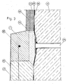
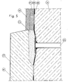
Figur 1 Die Ausbildung der Parzellierung einer abzudichtenden Fläche mittels Formstahlprofilen, deren Verankerung, die Dränung aus Einkornbeton sowie dessen Entwässerung bei einem dreischichtigen Belagaufbau.Figur 2 WieFigur 1 ,jedoch bei einem zweischichtigen Belagaufbau.Figur 3 Ausführung einer Dränung einer Brückenfläche unter dem Schrammbord, wobei der Einkornbeton gleichzeitig als Auflager für den Schrammbord selbst dient und die Gehwegkappe anschließend betoniert wird.Figur 4 Wie vor, jedoch bei einer Instandsetzung der Abdichtung, wenn die Gehwegkappe bereits betoniert ist und erhalten bleibt. Bei dieser Bauweise läßt sich unter dem Schrammbord eine gute Überlappung der alten mit der neuen Abdichtung herstellen.Figur 5 Wie vor, jedoch ohne Fetigteilschrammbord. In diesem Fall wird die Dränung vorab eingebaut und gegenüber dem nachfolgenden Beton mit einer Pappeschicht abgedicht.
- Figure 1 The formation of the parcelling of a surface to be sealed by means of shaped steel profiles, their anchoring, the drainage from Einkornbeton and its drainage in a three-layer covering.
- Figure 2 Like Figure 1, but with a two-layer covering structure.
- Figure 3 Execution of a drainage of a bridge surface under the curb, the Einkornbeton also serves as a support for the curb itself and the pavement cap is then concreted.
- Figure 4 As before, but with a repair of the seal, if the pavement cap is already concreted and is preserved. With this construction method, a good overlap of the old with the new seal can be created under the scrap board.
- Figure 5 As before, but without Fetigteilschrammbord. In this case, the drainage is installed in advance and sealed against the subsequent concrete with a layer of cardboard.
In den Figuren bedeuten:
- 1 Schrammbordfertigteil
- 2 Einkornbeton mit Epoxidharzbindemittel
- 3 Entwässerungsrohr
- 4 Abzudichtender Beton
- 5 Gehwegkappenbeton
- 6 Asphaltbetonschicht
- 7 Gußasphaltschicht
- 8 Abdichtung
- 9 Entwässerungsschicht
- 10 Schrammbordverankerung
- 11 Fuge
- 12 Fugenverguß
- 13 Gehwegbeschichtung
- 14 Formstahlprofil
- 15 Verankerung des Formstahlprofiles
- 1 prefab part
- 2 single-grain concrete with epoxy resin binder
- 3 drainage pipe
- 4 Concrete to be sealed
- 5 pavement cap concrete
- 6 asphalt concrete layer
- 7 Mastic asphalt layer
- 8 sealing
- 9 drainage layer
- 10 Scratchboard anchorage
- 11 fugue
- 12 grouting
- 13 Sidewalk coating
- 14 shaped steel profile
- 15 Anchoring the shaped steel profile
Vorrichtung auf Abdichtungen von flächenhaften Bauteilen zu deren Entwässerung, Parzellierung und Herstellung einer Verzahnung zwischen Abdichtung und der darüber angeordneten Schicht auf Brücken, Parkdecks, Wannen, Grundwasserschutzanlagen und dergleichen.Device for the sealing of flat components for their drainage, parcelling and production of a toothing between the sealing and the layer arranged above on bridges, parking decks, tubs, groundwater protection systems and the like.
Claims (5)
Applications Claiming Priority (2)
| Application Number | Priority Date | Filing Date | Title |
|---|---|---|---|
| DE3834889 | 1988-10-13 | ||
| DE19883834889 DE3834889A1 (en) | 1988-10-13 | 1988-10-13 | DEVICE ON SEALS OF AREA COMPONENTS FOR THEIR DRAINAGE, PARCELLATION AND PRODUCTION OF INTERLOCKING BETWEEN SEALING AND THE LAYER THEREOF ON BRIDGES, PARKING CEILINGS, TUBS, GROUNDWATER PROTECTION SYSTEMS |
Publications (2)
| Publication Number | Publication Date |
|---|---|
| EP0363709A2 true EP0363709A2 (en) | 1990-04-18 |
| EP0363709A3 EP0363709A3 (en) | 1990-11-22 |
Family
ID=6365044
Family Applications (1)
| Application Number | Title | Priority Date | Filing Date |
|---|---|---|---|
| EP19890117566 Withdrawn EP0363709A3 (en) | 1988-10-13 | 1989-09-22 | Device for use at seals of planar construction parts for drainage, parcelling and production of a toothing between seal and layer applied thereto, for bridges, parking ramps, reservoirs, ground water protection plants and the like |
Country Status (2)
| Country | Link |
|---|---|
| EP (1) | EP0363709A3 (en) |
| DE (1) | DE3834889A1 (en) |
Cited By (2)
| Publication number | Priority date | Publication date | Assignee | Title |
|---|---|---|---|---|
| RU2205913C1 (en) * | 2001-12-18 | 2003-06-10 | Общество с ограниченной ответственностью "НПП СК МОСТ" | Facility removing moisture from mass of pavement of bridge structure |
| CN112815862A (en) * | 2020-12-31 | 2021-05-18 | 江苏中路工程技术研究院有限公司 | Steel bridge deck pavement interlayer bonding state monitoring system and void detection method |
Families Citing this family (1)
| Publication number | Priority date | Publication date | Assignee | Title |
|---|---|---|---|---|
| DE20015289U1 (en) | 2000-09-05 | 2000-11-30 | Strabag Straßen- und Tiefbau AG, 50679 Köln | Covering for flat concrete structures |
Family Cites Families (6)
| Publication number | Priority date | Publication date | Assignee | Title |
|---|---|---|---|---|
| DE1229573B (en) * | 1964-07-20 | 1966-12-01 | Teerbau Gmbh Strassenbau | Bridge roadway with a mastic covering |
| DE2051607C3 (en) * | 1970-10-21 | 1980-04-03 | Dynamit Nobel Ag, 5210 Troisdorf | Multi-layer covering for sealing raw ceilings in building construction, civil engineering and civil engineering as well as processes for its production |
| DE3043633C2 (en) * | 1980-11-19 | 1982-08-19 | Willibald 7060 Schorndorf Luber | Device for draining concrete bridge seals |
| BE898930A (en) * | 1984-02-17 | 1984-06-18 | Moot Willem H | Multidirectional expansion joint for civil engineering projects - comprises profile which supports removable separating strip during casting, resulting groove being filled with elastics |
| DE3435983A1 (en) * | 1984-10-01 | 1986-04-17 | Ed. Züblin AG, 7000 Stuttgart | Arrangement for the base seal of storage basins and landfill sites |
| DE8533585U1 (en) * | 1985-11-29 | 1986-01-23 | G.H. Stahl- u. Leichtgerüstbau GmbH, 6052 Mühlheim | Safety device for bridge structures |
-
1988
- 1988-10-13 DE DE19883834889 patent/DE3834889A1/en not_active Withdrawn
-
1989
- 1989-09-22 EP EP19890117566 patent/EP0363709A3/en not_active Withdrawn
Cited By (2)
| Publication number | Priority date | Publication date | Assignee | Title |
|---|---|---|---|---|
| RU2205913C1 (en) * | 2001-12-18 | 2003-06-10 | Общество с ограниченной ответственностью "НПП СК МОСТ" | Facility removing moisture from mass of pavement of bridge structure |
| CN112815862A (en) * | 2020-12-31 | 2021-05-18 | 江苏中路工程技术研究院有限公司 | Steel bridge deck pavement interlayer bonding state monitoring system and void detection method |
Also Published As
| Publication number | Publication date |
|---|---|
| EP0363709A3 (en) | 1990-11-22 |
| DE3834889A1 (en) | 1990-04-19 |
Similar Documents
| Publication | Publication Date | Title |
|---|---|---|
| DD282487A5 (en) | EXPANSION JOINT CLOSURE AND METHOD OF MANUFACTURING | |
| DE2121981A1 (en) | Reinforced elastomeric joint sealant for bridges and other structures | |
| DE69300356T2 (en) | Liquid-tight floor for gas station. | |
| EP0363709A2 (en) | Device for use at seals of planar construction parts for drainage, parcelling and production of a toothing between seal and layer applied thereto, for bridges, parking ramps, reservoirs, ground water protection plants and the like | |
| DE2850329A1 (en) | PROCEDURE FOR FILLING OR PARTIAL FILLING OF A HOLE IN THE BOTTOM | |
| AT5560U1 (en) | COVERING FOR SURFACE CONCRETE CONSTRUCTIONS | |
| DE3833720A1 (en) | Method for producing a superstructure for railways | |
| DE202013103285U1 (en) | Dilatation and contraction joints in concrete traffic areas | |
| DE69019165T2 (en) | CONSTRUCTION STRUCTURE, ESPECIALLY A STREET BRIDGE STRUCTURE AND METHOD FOR THE PRODUCTION THEREOF. | |
| DE10055354B4 (en) | panel member | |
| DE4343482C2 (en) | Concrete structure for handling water-polluting substances | |
| DE2222429A1 (en) | Street joint sealing and end dam arrangement | |
| EP0253141B1 (en) | Prefabricated building element in particular staircase | |
| DE19716162C1 (en) | Flooring for parking garages, underground garages, parking decks or garages | |
| EP0834619B1 (en) | Filling station | |
| DE2219991B2 (en) | Joint edge made of synthetic resin concrete in road pavements | |
| DE102004055488B4 (en) | layer structure | |
| DE19710148C2 (en) | Cover for accessible manholes | |
| DE1484027C (en) | ||
| DE20210413U1 (en) | Ceiling construction especially for a parking garage | |
| DE102005032566A1 (en) | Joint between concrete slabs, forming a walking/driving surface e.g. for multi-story car park decks and roofs, has an inserted joint profile to block poured concrete and support a joint seal | |
| DE19650105A1 (en) | Multi=storey car park | |
| DE29614144U1 (en) | In a liquid-tight paved or slab surface, flush-mounted drainage object | |
| DE8519404U1 (en) | Joint profile for concrete pavement | |
| DE3910140A1 (en) | Method for sealing an expansion joint of a roadway paving |
Legal Events
| Date | Code | Title | Description |
|---|---|---|---|
| PUAI | Public reference made under article 153(3) epc to a published international application that has entered the european phase |
Free format text: ORIGINAL CODE: 0009012 |
|
| AK | Designated contracting states |
Kind code of ref document: A2 Designated state(s): AT BE CH DE ES FR GB GR IT LI LU NL SE |
|
| RAP1 | Party data changed (applicant data changed or rights of an application transferred) |
Owner name: REAKU- HOBEIN GMBH |
|
| RIN1 | Information on inventor provided before grant (corrected) |
Inventor name: LUBER,WILLIBALD |
|
| PUAL | Search report despatched |
Free format text: ORIGINAL CODE: 0009013 |
|
| AK | Designated contracting states |
Kind code of ref document: A3 Designated state(s): AT BE CH DE ES FR GB GR IT LI LU NL SE |
|
| 17P | Request for examination filed |
Effective date: 19901221 |
|
| 17Q | First examination report despatched |
Effective date: 19920127 |
|
| STAA | Information on the status of an ep patent application or granted ep patent |
Free format text: STATUS: THE APPLICATION HAS BEEN WITHDRAWN |
|
| 18W | Application withdrawn |
Withdrawal date: 19920822 |