EP0363767A1 - Farbbildprojektionsgerät mit auf reduziertes Übersprechen zwischen Bildpunkten ausgelegten Flüssigkristall-Lichtventilen - Google Patents
Farbbildprojektionsgerät mit auf reduziertes Übersprechen zwischen Bildpunkten ausgelegten Flüssigkristall-Lichtventilen Download PDFInfo
- Publication number
- EP0363767A1 EP0363767A1 EP89118160A EP89118160A EP0363767A1 EP 0363767 A1 EP0363767 A1 EP 0363767A1 EP 89118160 A EP89118160 A EP 89118160A EP 89118160 A EP89118160 A EP 89118160A EP 0363767 A1 EP0363767 A1 EP 0363767A1
- Authority
- EP
- European Patent Office
- Prior art keywords
- liquid crystal
- crystal panel
- light
- simple matrix
- projection apparatus
- Prior art date
- Legal status (The legal status is an assumption and is not a legal conclusion. Google has not performed a legal analysis and makes no representation as to the accuracy of the status listed.)
- Granted
Links
- 239000004973 liquid crystal related substance Substances 0.000 title claims abstract description 127
- 239000011159 matrix material Substances 0.000 claims abstract description 43
- 239000000654 additive Substances 0.000 claims abstract description 6
- 230000000996 additive effect Effects 0.000 claims abstract description 6
- 239000000203 mixture Substances 0.000 claims abstract description 6
- 230000001276 controlling effect Effects 0.000 claims description 6
- 239000013078 crystal Substances 0.000 claims description 4
- 239000000306 component Substances 0.000 description 16
- 238000002834 transmittance Methods 0.000 description 16
- 239000000758 substrate Substances 0.000 description 10
- 239000011521 glass Substances 0.000 description 9
- 238000001228 spectrum Methods 0.000 description 5
- 230000000875 corresponding effect Effects 0.000 description 4
- 230000003287 optical effect Effects 0.000 description 4
- 238000010276 construction Methods 0.000 description 3
- 238000010586 diagram Methods 0.000 description 3
- 238000002474 experimental method Methods 0.000 description 3
- 239000010408 film Substances 0.000 description 3
- 230000009467 reduction Effects 0.000 description 3
- 239000004642 Polyimide Substances 0.000 description 2
- 239000003990 capacitor Substances 0.000 description 2
- 238000000576 coating method Methods 0.000 description 2
- 239000003086 colorant Substances 0.000 description 2
- 230000002349 favourable effect Effects 0.000 description 2
- 239000002184 metal Substances 0.000 description 2
- 238000000034 method Methods 0.000 description 2
- 238000012986 modification Methods 0.000 description 2
- 230000004048 modification Effects 0.000 description 2
- 229920001721 polyimide Polymers 0.000 description 2
- 229920000642 polymer Polymers 0.000 description 2
- 239000010409 thin film Substances 0.000 description 2
- 238000012935 Averaging Methods 0.000 description 1
- 239000004988 Nematic liquid crystal Substances 0.000 description 1
- 208000032366 Oversensing Diseases 0.000 description 1
- 229910052729 chemical element Inorganic materials 0.000 description 1
- 230000006866 deterioration Effects 0.000 description 1
- 230000000694 effects Effects 0.000 description 1
- 239000004744 fabric Substances 0.000 description 1
- 229910052736 halogen Inorganic materials 0.000 description 1
- 150000002367 halogens Chemical class 0.000 description 1
- 239000012212 insulator Substances 0.000 description 1
- 238000010030 laminating Methods 0.000 description 1
- 238000004519 manufacturing process Methods 0.000 description 1
- 239000000049 pigment Substances 0.000 description 1
- 229920001296 polysiloxane Polymers 0.000 description 1
- 230000008569 process Effects 0.000 description 1
- 230000000644 propagated effect Effects 0.000 description 1
- 230000004044 response Effects 0.000 description 1
- 238000007789 sealing Methods 0.000 description 1
- 239000000126 substance Substances 0.000 description 1
- 230000007704 transition Effects 0.000 description 1
- 229910052724 xenon Inorganic materials 0.000 description 1
- FHNFHKCVQCLJFQ-UHFFFAOYSA-N xenon atom Chemical compound [Xe] FHNFHKCVQCLJFQ-UHFFFAOYSA-N 0.000 description 1
Images


Classifications
-
- H—ELECTRICITY
- H04—ELECTRIC COMMUNICATION TECHNIQUE
- H04N—PICTORIAL COMMUNICATION, e.g. TELEVISION
- H04N5/00—Details of television systems
- H04N5/74—Projection arrangements for image reproduction, e.g. using eidophor
-
- H—ELECTRICITY
- H04—ELECTRIC COMMUNICATION TECHNIQUE
- H04N—PICTORIAL COMMUNICATION, e.g. TELEVISION
- H04N9/00—Details of colour television systems
- H04N9/12—Picture reproducers
- H04N9/31—Projection devices for colour picture display, e.g. using electronic spatial light modulators [ESLM]
- H04N9/3102—Projection devices for colour picture display, e.g. using electronic spatial light modulators [ESLM] using two-dimensional electronic spatial light modulators
- H04N9/3105—Projection devices for colour picture display, e.g. using electronic spatial light modulators [ESLM] using two-dimensional electronic spatial light modulators for displaying all colours simultaneously, e.g. by using two or more electronic spatial light modulators
Definitions
- the present invention generally relates to a projection arrangement, and more particularly, to a projection apparatus arranged to independently control respective color light components of additive process three primary colors (red, green and blue) for a color image to be reproduced, by three liquid crystal panels, and to reproduce said color image by subjecting the respective color light components to additive mixture.
- the liquid crystal panel referred to above is generally so constructed as to include as constituting elements, a large number of picture element electrodes at least arranged in a dot matrix pattern, and a liquid crystal layer for modulating light according to voltages applied thereto, thereby to display arbitrary single color images including a half tone by applying image signals corresponding to respective picture elements.
- liquid crystal panels such as twisted-nematic (TN), guest-host (GH), dynamic scattering mode (DSM), double refraction (DAP or ECB, etc.), phase transition, and the like.
- TN twisted-nematic
- GH guest-host
- DSM dynamic scattering mode
- DAP double refraction
- ECB double refraction
- phase transition and the like.
- line electrodes and row electrodes are provided in a stripe pattern on respective two substrates, which are applied to each other so that the line and row electrodes cross each other to constitute the panel.
- Line selecting signals are successively applied to the line electrodes, while image signals are impressed to the row electrodes in synchronization with the line selecting signals.
- the intersecting points between the line electrodes and row electrodes constitute the picture elements, and the liquid crystal held between the both electrodes varies in its optical characteristic in response to the potential difference thereof.
- liquid crystal is an element responding to effective values
- generation of cross-talk is brought into question in the general driving in which voltage averaging method is applied to the TN mode or GH mode, and thus, the number of scanning lines can not be set very large.
- a non-linear element such as a varistor, NIM (Metal/Insulator/Metal) or the like is added to each picture element for suppressing the cross-talk.
- a switching transistor is added to each picture element for individual driving.
- Driving voltage is applied during the selecting period so as to be charged into an accumulating capacitor for being maintained also during the non-selecting period.
- the accumulating capacitor may be abbreviated.
- a thin film transistor (TFT) or MOS-FET and the like formed on a silicone wafer may be employed.
- the arrangement of the item (3) provided with the switching element is employed in the above three systems for the liquid crystal panel.
- the liquid crystal panel of the system in the above item (3) has such a problem that mass-production thereof is difficult, with a consequent increase in cost, similarly to the liquid crystal of the item (2).
- liquid crystal panel of the simple matrix system in the item (1) can be readily manufactured on a large scale for cost reduction, generation of the cross-talk is brought into question in the general driving by the TN mode, GH mode as referred to earlier, with such a drawback that the display contrast is undesirably lowered as the number of scanning lines is increased.
- an essential object of the present invention is to provide a projection apparatus employing a liquid crystal panel which can be readily manufactured on a large scale for reduction in cost, and is capable of providing a favorable contrast in the display.
- Another object of the present invention is to provide a projection apparatus of the above described type which is stable in functioning at high reliability.
- a projection apparatus which includes three liquid crystal panels for independently controlling respective color light components of red, green and blue for a color image to be reproduced, and means for subjecting the respective color light components to additive mixture so as to reproduce the color image.
- Each of the liquid crystal panels is constituted by a nematic type simple matrix liquid crystal panel having twist angle ⁇ of its liquid crystal molecule represented by 210° ⁇ ⁇ 300°
- the display contrast may be advantageously improved.
- Fig. 1 a schematic diagram showing construction of an optical system for a projection apparatus according to one preferred embodiment of the present invention.
- a condenser lens 1 In Fig. 1, light emitted from a light source 2 is converged by a condenser lens 1 into parallel rays, which are directed to a dichroic mirror 3a.
- an incandescent lamp, halogen lamp, xenon lamp or the like may be employed, and the spectrum of the light source 2 need not necessarily be of continuous spectrum, but may be of bright line spectrum for red, green and blue emitted by a fluorescent lamp or discharge tube.
- center wavelengths of the bright line spectrum are in the vicinity of 620 nm for the red light, 550 nm for the green light, and 450 nm for the blue light from the viewpoints of color reproducing range of the projection apparatus, and also of interchangeability with television signals of NTSC system.
- the dichroic mirror 3a formed by laminating a plurality of thin films having different refraction indexes has a function to reflect only light rays of particular wavelength region by an interference effect and to allow other light rays to pass therethrough.
- the dichroic mirror 3a is adapted to selectively reflect the blue light in the light rays from the light source 2 projected through the condenser lens 1, and to permit other light rays to pass therethrough.
- the blue light reflected by the dichroic mirror 3a is again reflected by a mirror 4a, and in the course of a light path of the reflected light, a first simple matrix liquid crystal panel 5a is provided.
- the blue light transmitted through said liquid crystal panel 5a is reflected by a mirror 4b so as to be further reflected by another dichroic mirror 3b, which has the function to selectively reflect the blue light in the similar manner as in the dichroic mirror 3a described earlier.
- the light reflected by the dichroic mirror 3b is converged by a projection lens 6 so as to be projected onto a screen 7.
- dichroic mirror 3c which has the function to selectively reflect the red light and to allow other light rays to pass therethrough, and the red light reflected by said dichroic mirror 3c is further reflected by mirrors 4c and 4d.
- a second simple matrix liquid crystal panel 5b is provided, and the red light transmitted through this simple matrix liquid crystal panel 5b is reflected by another dichroic mirror 3d having the function to selectively reflect the red light in the similar manner as in the dichroic mirror 3c referred to earlier, and to permit other light rays to pass therethrough.
- the red light reflected by the dichroic mirror 3d is transmitted through the dichroic mirror 3b and converged by a projection lens 6 so as to be projected onto the screen 7.
- a third simple matrix liquid crystal panel 5c is provided, and the green light transmitted through said liquid crystal panel 5c further passes through dichroic mirrors 3d and 3b so as to be converged by the projection lens 6 and projected onto the screen 7.
- Fig. 2 schematically showing the construction of each of the simple matrix liquid crystal panels 5a, 5b and 5c, on the confronting surfaces of one glass substrate 8 and the other glass substrate 9, transparent electrodes 10 and 11 are respectively formed in patterns, and these transparent electrodes 10 and 11 are arranged to cross each other.
- aligning films 12 and 13 composed of coatings by polyimide group high polymer are respectively formed, and further, surfaces of the films 12 and 13 are subjected to rubbing treatment by cloth in one direction.
- a liquid crystal layer 14 is disposed so as to be sealed therein by a sealing member (not shown). Moreover, over the surfaces of the glass substrates 8 and 9 directed opposite to each other, polarizing plates 15 and 16 are respectively provided. In each of these simple matrix liquid crystal panels 5a, 5b and 5c, picture elements are formed at respective portions of the liquid crystal layer 14 where the transparent electrodes 10 and 11 cross each other.
- FIG. 3 showing the relation between the rubbing angle and twist angle of the liquid crystal molecule in the simple matrix liquid crystal panel 5a, 5b or 5c.
- the twist angle of the liquid crystal molecule may be represented by an angle ⁇ formed by the rubbing direction 17 of the one glass substrate 8 (i.e. the long-axis or parallel direction of the liquid crystal molecule on the glass substrate 8) and the rubbing direction 18 of the other glass substrate 9, and the direction of a polarizing axis of the polarizing plate 15 is deviated by an angle ⁇ with respect to the rubbing direction 17 of the one glass substrate 8, while that of the polarizing plate 16 with respect to the rubbing direction 18 of the other glass substrate 9 is deviated by an angle ⁇ .
- the twist angle ⁇ of the liquid crystal molecule is set to be 270°.
- each of the simple matrix liquid crystal panels 5a, 5b and 5c in this case is of a super twisted nematic type (referred to as STN hereinafter), and an optical substance S-811 (name used in trade and manufactured by Merck Co.,) is added to the liquid crystal by 1.27 weight % so that the twist angle ⁇ thereof becomes 270°.
- the layer thickness d of the liquid crystal layer 14 in this case is set at 6.7 ⁇ m, with coatings of polyimide group high polymer being employed as the aligning films 12 and 13.
- Table 1 below shows compositions of the PCH group liquid crystal employed for the present embodiment.
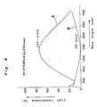
- the light transmittance characteristics of the liquid crystal panel 5c will be as shown in Fig. 4.
- a curve A represents the transmittance characteristic when a non-selected voltage waveform is applied across the two transparent electrodes 10 and 11, while a curve B shows the transmittance characteristic in the case where a selected voltage is applied across the transparent electrodes 10 and 11.
- this simple matrix liquid crystal panel 5c is to have a sufficient photo-switch function particularly for the green light.
- the range of ⁇ n ⁇ d for practical application should preferably be set as represented by 0.3 ⁇ m ⁇ ⁇ n ⁇ d ⁇ 1.6 ⁇ m (1) Similar results may be obtained thereby even when liquid crystals other than the PCH group liquid crystal are employed.
- the twist angle ⁇ of the liquid crystal molecule should desirably be set as large as possible, but excessive increase of said angle may result in generation of a domain due to disturbing in the alignment of the liquid crystal molecules, thus lowering the contrast ratio through scattering of light. Therefore, the range of the twist angle ⁇ for the practical application should be set as 210° ⁇ ⁇ ⁇ 300° (3)
- the value ⁇ n ⁇ d may be set with the range of the formula (1) according to the wavelengths of light allowed to pass therethrough, with other conditions being set in the similar manner as in the liquid crystal panel 5c.
- the simple matrix liquid crystal panels 5a, 5b and 5c have only to control transmittance of the blue, red and green lights respectively, and it is not necessarily required to have color filters incorporated within the respective liquid crystal panels 5a, 5b and 5c themselves or to have color pigments or the like contained in the liquid crystal.
- the light emitted from the light source 2 is converged by the condenser lens 1 so as to be formed into parallel rays, and is directed to the dichroic mirror 3a.
- the blue light is reflected by the dichroic mirror 3a, while other light rays are transmitted through said dichroic mirror 3a.
- the blue light reflected by the mirror 3a is further reflected by the mirror 4a so as to be projected onto the first simple matrix liquid crystal panel 5a.
- this simple matrix liquid crystal panel 5a a voltage corresponding to the blue light component of the color image to be reproduced is applied to the respective picture elements composed of the liquid crystal layer 14 through the transparent electrodes 10 and 11 shown in Fig. 2, whereby light transmittance of each picture element portion is varied.
- the blue light passing through the simple matrix liquid crystal panel 5a is reflected by the mirror 4b and the dichroic mirror 3b, and is converged by the projection lens 6 so as to be projected onto the screen 7.
- the blue light component transmitted through the first simple matrix liquid crystal panel 5a forms on the screen 7, the image for the blue light component of the color image to be produced.
- the red light component is reflected by the next dichroic mirror 3c, and further, by the mirrors 4c and 4d so as to be projected onto the second simple matrix liquid crystal panel 5b.
- this liquid crystal panel 5b in synchronization with the liquid crystal panel 5a referred to above, a voltage corresponding to the red light component of the color image to be reproduced, is impressed to the respective picture elements through its transparent electrodes 10 and 11, whereby light transmittance of the respective picture elements is altered.
- the red light component which has passed through the simple matrix liquid crystal panel 5b is transmitted through the subsequent dichroic mirror 3b, and converged by the projection lens 6 so as to be projected onto the screen 7.
- the red light which has passed through the second simple matrix liquid crystal panel 5b forms on the screen 7, the image for the red light component of the color image to be reproduced.
- the green light component passing through the dichroic mirror 3c is projected onto the third simple matrix liquid crystal panel 5c.
- this liquid crystal panel 5c in synchronization with the liquid crystal panels 5a and 5b referred to earlier, a voltage corresponding to the green light component of the color image to be reproduced, is impressed to the respective picture elements through its transparent electrodes 10 and 11, whereby light transmittance of the respective picture elements is altered.
- the green light component which has passed through the simple matrix liquid crystal panel 5c is transmitted through the next dichroic mirrors 3d and 3b, and converged by the projection lens 6 so as to be projected onto the screen 7.
- the green light component which has passed through the third simple matrix liquid crystal panel 5c forms on the screen 7, the image for the green light component of the color image to be reproduced.
- the apparatus of the present invention has a larger degree of freedom for selecting installing places, and thus, it becomes possible to project onto a ceiling or to project onto a wall by suspending the apparatus from the ceiling.
- the size of the projected image may be altered as desired by varying the projecting distance or by replacing the projection lens.
- the wavelength regions of the respective light rays for the red, blue and green to be controlled by the simple matrix liquid crystal panels 5a, 5b and 5c should be set as follows for the optimum results, in which ⁇ R denotes the peak wavelength for the red, ⁇ G represents the peak wavelength for the green, and ⁇ B shows the peak wavelength for the blue.
- Red 600 nm ⁇ ⁇ R ⁇ 650 nm, with a half width being less than 50nm.
- Green 520 nm ⁇ ⁇ G ⁇ 570 nm, with a half width being less than 50 nm.
- Blue 420 nm ⁇ ⁇ B ⁇ 470 nm, with a half width being less than 50 nm.
- the refractive index anisotropy ⁇ nR (for the liquid crystal in the liquid crystal panel 5b), ⁇ n G (for the liquid crystal in the crystal panel 5c), and ⁇ n B (for the liquid crystal in the crystal panel 5a), and the liquid crystal layer thicknesses d R (for the liquid crystal in the liquid crystal panel 5b), d G (for the liquid crystal in the liquid crystal panel 5c), and d B (for the liquid crystal in the liquid crystal panel 5a) of the respective liquid crystals should be optimized as follows.
- the maximum contrast has been obtained when the value C equals 1.4.
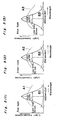
- Figs. 5(1), 5(2) and 5(3) show light transmittance characteristics of the respective simple matrix liquid crystal panels 5a, 5b and 5c under the conditions as described above. More specifically, Fig. 5(1) represents in dotted lines the light transmittance characteristic of the liquid crystal panel 5b for controlling the red light (as shown in solid line, its peak wavelength ⁇ R is 620 nm, and the half width being less than 50 nm), Fig. 5 (2) represents in dotted lines the light transmittance characteristic of the liquid crystal panel 5c for controlling the green light (as shown in solid line, its peak wavelength ⁇ G is 550 nm, and the half width being less than 50 nm), and Fig. 5 (3) represents in dotted lines the light transmittance characteristic of the liquid crystal panel 5a for controlling the blue light (as shown in solid lines, its peak wavelength ⁇ B is 450 nm, and the half width being less than 50 nm).
- the dotted lines A1 to A3 respectively relate to the light transmittance characteristics when non-selective voltage waveforms are applied, while the dotted lines B1 to B3 respectively denote the light transmittance characteristics when selective voltage waveforms are impressed.
- each of the three liquid crystal panels is constituted by the simple matrix liquid crystal panel of super-twisted nematic type, such liquid crystal panels may be produced on a large scale, with a simultaneous reduction in cost, and thus, color images superior in the display contrast may be advantageously presented.
Landscapes
- Engineering & Computer Science (AREA)
- Multimedia (AREA)
- Signal Processing (AREA)
- Liquid Crystal (AREA)
- Transforming Electric Information Into Light Information (AREA)
- Devices For Indicating Variable Information By Combining Individual Elements (AREA)
Applications Claiming Priority (2)
| Application Number | Priority Date | Filing Date | Title |
|---|---|---|---|
| JP251196/88 | 1988-10-04 | ||
| JP63251196A JPH0642125B2 (ja) | 1988-10-04 | 1988-10-04 | プロジェクション装置 |
Publications (2)
| Publication Number | Publication Date |
|---|---|
| EP0363767A1 true EP0363767A1 (de) | 1990-04-18 |
| EP0363767B1 EP0363767B1 (de) | 1994-12-14 |
Family
ID=17219113
Family Applications (1)
| Application Number | Title | Priority Date | Filing Date |
|---|---|---|---|
| EP89118160A Expired - Lifetime EP0363767B1 (de) | 1988-10-04 | 1989-09-30 | Farbbildprojektionsgerät mit auf reduziertes Übersprechen zwischen Bildpunkten ausgelegten Flüssigkristall-Lichtventilen |
Country Status (5)
| Country | Link |
|---|---|
| US (1) | US5054910A (de) |
| EP (1) | EP0363767B1 (de) |
| JP (1) | JPH0642125B2 (de) |
| KR (1) | KR920006167B1 (de) |
| DE (1) | DE68919985T2 (de) |
Cited By (5)
| Publication number | Priority date | Publication date | Assignee | Title |
|---|---|---|---|---|
| GB2252173A (en) * | 1991-01-25 | 1992-07-29 | Rank Brimar Ltd | Colour optical output system |
| WO1992013424A1 (en) * | 1991-01-25 | 1992-08-06 | Rank Brimar Limited | Color optical output system |
| EP0521336A1 (de) * | 1991-06-21 | 1993-01-07 | Eastman Kodak Company | System und Verfahren zum Reproduzieren eines Bildes |
| US5253074A (en) * | 1990-12-19 | 1993-10-12 | U.S. Philips Corporation | Temperature compensated color LCD projector |
| US5638142A (en) * | 1992-04-03 | 1997-06-10 | Rank Brimar Limited | Spatial light modulator system including a plurality of tiltable mirror devices and reflective means for equalizing the number of reflections from the tiltable mirror devices |
Families Citing this family (17)
| Publication number | Priority date | Publication date | Assignee | Title |
|---|---|---|---|---|
| US5235446A (en) * | 1989-02-09 | 1993-08-10 | Sharp Kabushiki Kaisha | Projection type liquid crystal display apparatus with pixels of one panel |
| US5140466A (en) * | 1990-12-20 | 1992-08-18 | Hughes Aircraft Company | Optical multiplexer |
| US5666175A (en) * | 1990-12-31 | 1997-09-09 | Kopin Corporation | Optical systems for displays |
| US5317436A (en) * | 1990-12-31 | 1994-05-31 | Kopin Corporation | A slide assembly for projector with active matrix moveably mounted to housing |
| US5396304A (en) * | 1990-12-31 | 1995-03-07 | Kopin Corporation | Slide projector mountable light valve display |
| EP1257128B1 (de) * | 1993-03-16 | 2004-03-03 | Seiko Epson Corporation | Projektionsanzeigevorrichtung |
| GB2278927A (en) * | 1993-06-12 | 1994-12-14 | Central Research Lab Ltd | Liquid crystal optical projector arrangement |
| US5624174A (en) * | 1993-08-25 | 1997-04-29 | Kopin Corporation | Display panel mount for projection display system |
| US5455678A (en) * | 1993-08-25 | 1995-10-03 | Kopin Corporation | Method for mounting light valves for projection display system |
| US5664859A (en) * | 1994-01-03 | 1997-09-09 | Kopin Corporation | Projection display docking system |
| US5806950A (en) * | 1994-06-03 | 1998-09-15 | Kopin Corporation | Compact high resolution light valve projector |
| US5550604A (en) * | 1994-06-03 | 1996-08-27 | Kopin Corporation | Compact high resolution light valve projector |
| USD368730S (en) | 1994-09-28 | 1996-04-09 | Kopin Corporation | Compact light valve projector |
| US5630659A (en) * | 1994-09-28 | 1997-05-20 | Kopin Corporation | Compact high resolution light valve projector |
| FR2731526B1 (fr) * | 1995-03-09 | 1997-04-04 | Thomson Consumer Electronics | Ecran a cristaux liquides a angle de vue ameliore |
| CA2195278C (en) * | 1996-01-22 | 2004-07-27 | Teruyasu Fukuyama | Process for producing quick-boiling or instant cooking pastas and noodles |
| JP3893533B2 (ja) * | 2001-02-09 | 2007-03-14 | 株式会社日立製作所 | 液晶表示装置 |
Citations (2)
| Publication number | Priority date | Publication date | Assignee | Title |
|---|---|---|---|---|
| EP0266184A2 (de) * | 1986-10-31 | 1988-05-04 | Seiko Epson Corporation | Anzeigevorrichtung vom Projektionstyp |
| EP0311116A2 (de) * | 1987-10-09 | 1989-04-12 | Matsushita Electric Industrial Co., Ltd. | Projektions-Flüssigkristall-Anzeigevorrichtung |
Family Cites Families (10)
| Publication number | Priority date | Publication date | Assignee | Title |
|---|---|---|---|---|
| US4171874A (en) * | 1975-02-03 | 1979-10-23 | General Electric Company | Evenly illuminated display devices |
| US4378955A (en) * | 1979-08-03 | 1983-04-05 | Hughes Aircraft Company | Method of and apparatus for a multimode image display with a liquid crystal light valve |
| US4601543A (en) * | 1982-10-15 | 1986-07-22 | At&T Bell Laboratories | Nematic liquid crystal storage display device |
| CH664027A5 (de) * | 1983-07-12 | 1988-01-29 | Bbc Brown Boveri & Cie | Fluessigkristallanzeige. |
| IN161652B (de) * | 1983-07-12 | 1988-01-09 | Bbc Brown Boveri & Cie | |
| US4850685A (en) * | 1984-10-22 | 1989-07-25 | Seiko Epson Corporation | Projection-type color display device |
| JPH0628461B2 (ja) * | 1984-10-25 | 1994-04-13 | ソニー株式会社 | 投写型表示装置 |
| GB2198867A (en) * | 1986-12-17 | 1988-06-22 | Philips Electronic Associated | A liquid crystal display illumination system |
| JPS63167331A (ja) * | 1986-12-29 | 1988-07-11 | Sharp Corp | ツイステツド・ネマチツク型液晶表示素子 |
| US5040877A (en) * | 1987-12-04 | 1991-08-20 | Kent State University | Low loss liquid crystal modulator for coloring and shaping a light beam |
-
1988
- 1988-10-04 JP JP63251196A patent/JPH0642125B2/ja not_active Expired - Lifetime
-
1989
- 1989-09-30 DE DE68919985T patent/DE68919985T2/de not_active Expired - Fee Related
- 1989-09-30 EP EP89118160A patent/EP0363767B1/de not_active Expired - Lifetime
- 1989-10-02 US US07/415,711 patent/US5054910A/en not_active Expired - Lifetime
- 1989-10-04 KR KR1019890014270A patent/KR920006167B1/ko not_active Expired
Patent Citations (2)
| Publication number | Priority date | Publication date | Assignee | Title |
|---|---|---|---|---|
| EP0266184A2 (de) * | 1986-10-31 | 1988-05-04 | Seiko Epson Corporation | Anzeigevorrichtung vom Projektionstyp |
| EP0311116A2 (de) * | 1987-10-09 | 1989-04-12 | Matsushita Electric Industrial Co., Ltd. | Projektions-Flüssigkristall-Anzeigevorrichtung |
Non-Patent Citations (2)
| Title |
|---|
| PATENT ABSTRACTS OF JAPAN, vol. 11, no. 386 (P-647)[2833], 17th December 1987, page 153 P 647; & JP-A-62 153 821 (STANLEY ELECTRIC CO. LTD) 08-07-1987 * |
| SOCIETY FOR INFORMATION DISPLAY INTERNATIONAL SYMPOSIUM, DIGEST OF TECHNICAL PAPERS, New Orleans, Louisiana, 12th-14th May 1987, vol. 18, pages 75-78, SID, New York, US; S. ARUGA et al.: "High-resolution full-color video projector with poly-Si TFT array light valves" * |
Cited By (7)
| Publication number | Priority date | Publication date | Assignee | Title |
|---|---|---|---|---|
| US5253074A (en) * | 1990-12-19 | 1993-10-12 | U.S. Philips Corporation | Temperature compensated color LCD projector |
| USRE37056E1 (en) * | 1990-12-19 | 2001-02-20 | U.S. Philips Corporation | Temperature compensated color LCD projector |
| GB2252173A (en) * | 1991-01-25 | 1992-07-29 | Rank Brimar Ltd | Colour optical output system |
| WO1992013424A1 (en) * | 1991-01-25 | 1992-08-06 | Rank Brimar Limited | Color optical output system |
| US5424868A (en) * | 1991-01-25 | 1995-06-13 | Rank Brimar Limited | Color optical output system |
| EP0521336A1 (de) * | 1991-06-21 | 1993-01-07 | Eastman Kodak Company | System und Verfahren zum Reproduzieren eines Bildes |
| US5638142A (en) * | 1992-04-03 | 1997-06-10 | Rank Brimar Limited | Spatial light modulator system including a plurality of tiltable mirror devices and reflective means for equalizing the number of reflections from the tiltable mirror devices |
Also Published As
| Publication number | Publication date |
|---|---|
| JPH0297992A (ja) | 1990-04-10 |
| KR920006167B1 (ko) | 1992-07-31 |
| KR900007237A (ko) | 1990-05-09 |
| DE68919985T2 (de) | 1995-05-04 |
| DE68919985D1 (de) | 1995-01-26 |
| JPH0642125B2 (ja) | 1994-06-01 |
| US5054910A (en) | 1991-10-08 |
| EP0363767B1 (de) | 1994-12-14 |
Similar Documents
| Publication | Publication Date | Title |
|---|---|---|
| EP0363767B1 (de) | Farbbildprojektionsgerät mit auf reduziertes Übersprechen zwischen Bildpunkten ausgelegten Flüssigkristall-Lichtventilen | |
| US5686931A (en) | Device for displaying colors produced by controllable cholesteric color filters | |
| US6545653B1 (en) | Method and device for displaying image signals and viewfinder | |
| US6327093B1 (en) | Image display apparatus | |
| US5737050A (en) | Light valve having reduced reflected light, high brightness and high contrast | |
| JP4149699B2 (ja) | 時分割方式液晶表示装置及びそのカラー映像表示方法 | |
| US7683880B2 (en) | Method of color image display for a field sequential liquid crystal display device | |
| US5642214A (en) | Optical modulating element and electronic apparatus using it | |
| US7042535B2 (en) | Optical display system and optical shifter | |
| US5347378A (en) | Fast switching color filters for frame-sequential video using ferroelectric liquid crystal color-selective filters | |
| US6177965B1 (en) | Display device and projection-type display apparatus using the device | |
| JPH07325214A (ja) | 色フィルタおよびそれを用いた投写型表示装置 | |
| Gerhard-Multhaupt | Light-valve technologies for high-definition television projection displays | |
| JPH04309995A (ja) | 液晶表示装置とそれを用いた液晶投写型テレビ | |
| DE69329167T2 (de) | Flüssigkristalltafel und Flüssigkristall-Projektions-Fernsehempfänger | |
| JPH04240689A (ja) | 液晶ビデオプロジェクター | |
| US5245451A (en) | Liquid crystal display method and apparatus with tuneable phase compensation | |
| US5058998A (en) | Liquid crystal display devide with a twisted alignment state | |
| US5610735A (en) | Light scattering light valve projection apparatus | |
| JP2532408B2 (ja) | 画像投影機 | |
| JP4446410B2 (ja) | 液晶表示素子及びこれを用いた液晶表示装置 | |
| JP2795618B2 (ja) | 投射型表示装置 | |
| Igasaki et al. | High speed parallel aligned liquid crystal spatial light modulator operated at 180 Hz | |
| Wakita et al. | Multi-color projection display | |
| JPH10206881A (ja) | 液晶インターレス表示装置 |
Legal Events
| Date | Code | Title | Description |
|---|---|---|---|
| PUAI | Public reference made under article 153(3) epc to a published international application that has entered the european phase |
Free format text: ORIGINAL CODE: 0009012 |
|
| 17P | Request for examination filed |
Effective date: 19890930 |
|
| AK | Designated contracting states |
Kind code of ref document: A1 Designated state(s): DE GB |
|
| 17Q | First examination report despatched |
Effective date: 19920827 |
|
| GRAA | (expected) grant |
Free format text: ORIGINAL CODE: 0009210 |
|
| AK | Designated contracting states |
Kind code of ref document: B1 Designated state(s): DE GB |
|
| REF | Corresponds to: |
Ref document number: 68919985 Country of ref document: DE Date of ref document: 19950126 |
|
| PLBE | No opposition filed within time limit |
Free format text: ORIGINAL CODE: 0009261 |
|
| STAA | Information on the status of an ep patent application or granted ep patent |
Free format text: STATUS: NO OPPOSITION FILED WITHIN TIME LIMIT |
|
| 26N | No opposition filed | ||
| PGFP | Annual fee paid to national office [announced via postgrant information from national office to epo] |
Ref country code: GB Payment date: 20011003 Year of fee payment: 13 |
|
| PGFP | Annual fee paid to national office [announced via postgrant information from national office to epo] |
Ref country code: DE Payment date: 20011015 Year of fee payment: 13 |
|
| REG | Reference to a national code |
Ref country code: GB Ref legal event code: IF02 |
|
| PG25 | Lapsed in a contracting state [announced via postgrant information from national office to epo] |
Ref country code: GB Free format text: LAPSE BECAUSE OF NON-PAYMENT OF DUE FEES Effective date: 20020930 |
|
| PG25 | Lapsed in a contracting state [announced via postgrant information from national office to epo] |
Ref country code: DE Free format text: LAPSE BECAUSE OF NON-PAYMENT OF DUE FEES Effective date: 20030401 |
|
| GBPC | Gb: european patent ceased through non-payment of renewal fee |
Effective date: 20020930 |