EP0363834A1 - Brûleur, particulièrement brûleur à haute vitesse - Google Patents
Brûleur, particulièrement brûleur à haute vitesse Download PDFInfo
- Publication number
- EP0363834A1 EP0363834A1 EP89118554A EP89118554A EP0363834A1 EP 0363834 A1 EP0363834 A1 EP 0363834A1 EP 89118554 A EP89118554 A EP 89118554A EP 89118554 A EP89118554 A EP 89118554A EP 0363834 A1 EP0363834 A1 EP 0363834A1
- Authority
- EP
- European Patent Office
- Prior art keywords
- combustion chamber
- outer tube
- flame holder
- burner according
- burner
- Prior art date
- Legal status (The legal status is an assumption and is not a legal conclusion. Google has not performed a legal analysis and makes no representation as to the accuracy of the status listed.)
- Granted
Links
Images




Classifications
-
- F—MECHANICAL ENGINEERING; LIGHTING; HEATING; WEAPONS; BLASTING
- F23—COMBUSTION APPARATUS; COMBUSTION PROCESSES
- F23D—BURNERS
- F23D14/00—Burners for combustion of a gas, e.g. of a gas stored under pressure as a liquid
- F23D14/46—Details
- F23D14/72—Safety devices, e.g. operative in case of failure of gas supply
- F23D14/74—Preventing flame lift-off
-
- F—MECHANICAL ENGINEERING; LIGHTING; HEATING; WEAPONS; BLASTING
- F23—COMBUSTION APPARATUS; COMBUSTION PROCESSES
- F23D—BURNERS
- F23D14/00—Burners for combustion of a gas, e.g. of a gas stored under pressure as a liquid
- F23D14/20—Non-premix gas burners, i.e. in which gaseous fuel is mixed with combustion air on arrival at the combustion zone
-
- F—MECHANICAL ENGINEERING; LIGHTING; HEATING; WEAPONS; BLASTING
- F23—COMBUSTION APPARATUS; COMBUSTION PROCESSES
- F23C—METHODS OR APPARATUS FOR COMBUSTION USING FLUID FUEL OR SOLID FUEL SUSPENDED IN A CARRIER GAS OR AIR
- F23C2900/00—Special features of, or arrangements for combustion apparatus using fluid fuels or solid fuels suspended in air; Combustion processes therefor
- F23C2900/03005—Burners with an internal combustion chamber, e.g. for obtaining an increased heat release, a high speed jet flame or being used for starting the combustion
Definitions
- the invention relates to a burner, in particular high-speed burners, having a housing which contains a flow channel for the oxygen carrier gas, an outer tube which has an open downstream end and is fastened to the housing with an upstream end in such a way that it forms a continuation of the flow channel , a combustion chamber which has an open downstream end and is inserted into the outer tube in such a way that its downstream end is substantially flush with the downstream end of the outer tube.
- a burner is known from VDI report No. 645, edition 1987, page 352, in which a combustion chamber is arranged inside an outer tube, the outer tube being fastened to a housing, in such a way that it is a continuation of one of the housing formed flow channel for an oxygen carrier gas.
- the end of the combustion chamber facing the housing has a flame holder which is designed as a flat burner plate.
- the burner plate is provided with openings for the passage of part of the oxygen carrier gas and also has a central inlet for a fuel.
- the part of the oxygen carrier gas flowing in the annular space between the combustion chamber and the outer tube is introduced into the latter through radial openings in front of the downstream end of the combustion chamber.
- the object of the invention is to create a burner, in particular a high-speed burner with improved combustion properties, in particular with improved flame stability and reduced pollutant emission, in particular with reduced NO x emission.
- a burner in particular high-speed burner, with a housing which contains a flow channel for an oxygen carrier gas, an outer tube which has an open downstream end and is attached to the housing with its upstream end in such a way that it is a continuation of the Flow channel forms a firewall, which has an open upstream end and an open downstream end and is inserted into the outer tube such that its downstream end is substantially aligned with the downstream end of the outer tube, the downstream ends of the outer tube and the combustion chamber form jet openings between them for the exit of a secondary part of the oxygen carrier gas, the jet openings being located at a circumferential distance from one another, a flame holder which is inserted into the upstream end of the combustion chamber and an essentially k Onic jacket, which extends in the flow direction from a central inlet of the flame holder against the combustion chamber and has openings for the passage of a primary part of the oxygen carrier gas and a device for supplying fuel to the flame holder.
- control range can be doubled over the known construction due to the improved flame stability, to a value of at least 1:40. This also applies to large outputs of 350 kW and more.
- the high-speed burner according to the invention is suitable for furnace temperatures of at least up to 1600 ° C.
- a particular advantage of the burner according to the invention is its low noise.
- the invention is based on the knowledge that the addition of the oxygen carrier gas, for. B. of secondary air, in front of the outlet opening of the combustion chamber leads to vigorous mixing and accordingly to a high thermal conversion. This leads to a comparatively high NO x formation.
- the oxygen carrier gas for grading the combustion is placed essentially radially on the outside of the flame emerging from the burner.
- the mixing of the oxygen carrier gas into the flame and the course of a second combustion stage can thus be controlled very well.
- an optimization between the flame length on the one hand and the NO x emission on the other hand can easily be achieved.
- the jacket of the flame holder preferably widens essentially conically. This results in a very good burning behavior with simple manufacture.
- the flame stability can also be increased in that a substantially cylindrical section is arranged at the downstream end of the casing, which section merges into a substantially radial flange adjoining the combustion chamber.
- the edge between the cylindrical section and the flange provides an additional flame holder.
- the passage openings of the flame holder form mutually offset rows which run around the jacket in the circumferential direction. This results in a very favorable flow passage through the flame holder.
- the latter effect is further promoted in that the axes of the passage openings are perpendicular to the tangents of the jacket pointing in the direction of flow and an angle of 90-45 ° with the tangents pointing in the circumferential direction shut down. If the latter angle is 90 °, the flame holder can also be manufactured very cheaply. As the angle increases, the swirl with which the flow enters the basket-shaped flame holder increases.
- the burner according to the invention can be a premixing burner.
- the fuel reaches the flame holder together with the oxygen carrier gas.
- This mixture can also contain a cooling gas, for example exhaust gas or water vapor.
- the burner is particularly advantageous to design the burner as a secondary air burner.
- the basket-shaped shape of the flame holder, to which the fuel is fed separately, and the staggering of the passage openings result in "stage combustion", which is characterized by low pollutant content, in particular by low NO x formation.
- the burner can preheat the air to more than 600 ° C. It is possible to operate the burner as a recuperator burner.
- the burner according to the invention is designed as a two-stage secondary burner.
- the flame stability guaranteed according to the invention offers the possibility of allowing the first stage, namely the "stage combustion" on the basket-shaped flame holder, to run with a very low air ratio and accordingly relocating a high proportion of the combustion to the second, already cooled stage.
- the combustion-appropriate, central supply of the fuel to the flame holder takes place according to the invention through a fuel lance with essentially radial outlet openings which open inside the flame holder.
- the controllability of the burner according to the invention to a low output value gives the possibility of igniting the burner directly while avoiding a pilot burner.
- the flame holder has an ignition opening at the level of the outlet openings of the fuel lance and that before the ignition Opening an ignition device is arranged in the guide for the oxygen carrier gas.
- the ignition spark or arc is drawn through the ignition opening by the oxygen carrier gas and can ignite the fuel emerging from the essentially radial outlet openings of the fuel lance.
- the ignition device is always in the cool area, namely in the guide outside the flame holder and is flushed there, like the outer wall of the flame holder, by the oxygen carrier gas, which is usually air.
- outlet openings of the fuel lance are at the level of a row of the through openings of the flame holder, one of these through openings works as an ignition opening.
- an essentially cylindrical section is arranged at the upstream end of the jacket of the flame holder and surrounds the outlet openings of the fuel lance. This leads to a very favorable introduction of the fuel into the basket-shaped flame holder.
- the fuel lance is screwed into a socket of a frontal base body of the housing and that the flame holder with the cylindrical section arranged at its upstream end is attached to the socket and is secured in a tensile manner.
- the flame holder and the fuel lance together with the base body form a common assembly that can be assembled and disassembled closed.
- the ignition device can preferably also belong to this assembly.
- the invention proposes that the cylindrical section arranged at the upstream end of the flame holder has a flushing opening. The latter establishes a connection to the guide for the oxygen carrier gas.
- the fuel lance has an attached tip provided with the outlet openings, which is secured by a continuous bolt which is supported in the cylindrical section arranged at the upstream end of the flame holder. If you pull the flame holder off the fuel lance, you can let the bolt fall out and remove the tip from the fuel lance.
- the fuel lance is advantageously supported with projections in the cylindrical section arranged at the upstream end of the flame holder. Between these projections you can look into the interior of the flames through the cylindrical section of the flame holder. Accordingly, the base body is preferably also provided with UV flame monitoring. The fuel lance is rotated so that its projections do not block the monitoring.
- the flame holder is slidably guided in the burner chamber connected to the housing. After detaching the base body from the housing, the entire assembly of the base body can then be pulled out of the burner. To facilitate this process, it is advisable to guide the flame holder with great tolerance in the combustion chamber. This has the further advantage that a cooling air curtain lies over the combustion chamber wall behind the flame holder.
- the combustion chamber is fastened in an outer tube connected to the housing, an assembly which can be removed from the housing in a closed manner also arises at the front end of the burner.
- the burner according to the invention can be characterized in that the burner chamber is guided with a nozzle in a nozzle of the outer tube and is supported upstream with projections in the outer tube.
- the flame holder and / or the tip of the fuel lance and / or the combustion chamber and / or the outer tube consist of ceramic material. This enables the burner to work as a high temperature burner.
- the burner chamber can be slotted onto the outer tube.
- the combustion chamber and outer tube form an inseparable unit.
- the invention also proposes that the combustion chamber be fastened to the outer tube by a bolt.
- This bolt can be glued in with an adhesive, it being possible to soften the adhesive by the action of heat and to loosen the connection.
- Another preferred feature is that the bolt is stepped and engages with its thicker portion in an opening in the outer tube; while it protrudes with its thinner section through an opening of the combustion chamber and is secured there with a split pin.
- the invention proposes that the bolt be offset and engage with its thinner portion in an opening of the outer tube and with its thicker portion in an opening of the combustion chamber, the bolt being supported by the flame holder.
- the edge of the opening of the combustion chamber can preferably be angled in order to prevent the bolt from tilting.
- the combustion chamber and / or the outer tube have at least one slot running essentially in the axial direction and extending at least over part of the length.
- the slot is preferably continuous. Depending on the pressure conditions, either small amounts of air can enter through the slot in the combustion chamber or combustion gases can escape. If this bothers, the slot can be at least partially preferably filled with the same ceramic material according to the invention. Now only thermal stresses, but no more manufacturing stresses, can cause the component to tear. The slot then forms a predetermined breaking point.
- three slots are evenly distributed over the circumference, either in the front or in the rear area.
- the slots run up to half of the component.
- a problem is the connection of the ceramic material to the housing of the burner.
- the invention solves the problem in that the outer tube is elastically braced against a ring that can be attached to the housing.
- the bracing is preset to the optimal value, and the assembly consisting of the combustion chamber and secondary air duct can then be assembled and disassembled by making or breaking the connection between the ring and the housing.
- the jet openings for the oxygen carrier gas are formed by indentations of the downstream end of the combustion chamber and / or indentations of the outer tube.
- Indentations in the combustion chamber lead to "channels" forming in the flame in which the rays are inserted.
- the beams are placed on the "undamaged" circumference of the flame.
- the indentations and bulges are offset from one another, some of the rays are embedded in the flame, while further rays are placed on the circumference of the flame.
- a structure is formed which is wavy in the circumferential direction.
- the invention thus offers a large number of possible combinations for controlling the mixing of the oxygen carrier gas into the flame and for cooling it.
- the exhaust gas recirculation which also influences the NO x emission.
- different layers of flame / secondary air / exhaust gas result.
- An advantageous construction provides that the jet openings formed between the downstream ends of the outer tube and the combustion chamber are connected to one another by gap sections running in the circumferential direction.
- the oxygen carrier gas emerging from the gap sections practically does not contribute to thorough mixing, but also supports the flame-reducing NO x caused by the oxygen carrier gas jets. It also cools the burner materials. However, it is extremely difficult to set the oxygen carrier gas throughput in the gap sections. Accordingly, the arrangement will preferably be made such that the gap width of the gap sections is small compared to the diameter of the jet openings.
- the downstream end of the combustion chamber and the outer tube preferably have a circularly symmetrical cross section. Any other cross-sections are also possible according to the invention, but a circular-symmetrical cross-section ensures an extremely uniform influence on the entire flame. There is also a uniform temperature distribution, which leads to a symmetrical material load.
- combustion chamber and the outer tube can be rotated relative to one another. This allows the indentations of the combustion chamber and the indentations of the casing to be brought into any relative positions with respect to one another.
- the combustion chamber can extend to the outlet opening with a constant cross section.
- the invention has a particularly advantageous effect on those gas burners in which the downstream end of the combustion chamber is designed as a nozzle, since the entry of the oxygen carrier gas in front of the narrowest cross section of the nozzle leads to particularly high NO x emissions.
- the jet openings for the oxygen carrier gas can be aligned in a convergent manner.
- the oxygen carrier gas jets are thus pressed into the flame in the manner desired in each case, which also gives the possibility of controlling the mixing.
- a corresponding design is characterized in that the outer tube converges towards the downstream end of the combustion chamber.
- the downstream end of the combustion chamber which is designed as a nozzle, can have, according to the invention, an end section that is parallel to the direction of flow and to the end of which the outer tube runs.
- the end of the combustion chamber preferably also runs parallel to the direction of flow.
- a radial flange is arranged at the downstream end of the combustion chamber, on the outer edge of which the outer tube runs.
- the oxygen carrier gas jets emerge from the jet openings at an increased distance from the base of the flame, which results in a particularly simple possibility for also placing an exhaust gas layer between the flame and the oxygen carrier gas jets. This increases the intensity of the mixing process.
- the invention proposes that the combustion chamber merge into the end face of the flange via a curve.
- the guidance of the oxygen carrier gas jets can be further improved according to the invention in that the outer tube protrudes slightly in the shape of a funnel above the downstream end of the nozzle.
- the construction according to the invention is particularly suitable for production from pourable, in particular ceramic material, since the jacket on the one hand and the combustion chamber on the other hand can be formed as separate components. It is then particularly advantageous that the downstream end is slidably guided in the jacket in order to avoid thermal stresses.
- the components preferably have the same wall thicknesses.
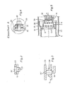
- the high-speed burner shown is a two-stage secondary air burner.
- the burner has a housing 1 which forms a guide 2 for an oxygen carrier gas, in the present case an air guide.
- a flame holder 3 is arranged in the guide and has through openings 4.
- a combustion chamber 5 adjoins the flame holder 3 and has a nozzle 6 at its downstream end.
- a fuel lance 7 is provided for supplying fuel to the flame holder 3.
- the fuel is gas.
- the passage openings 4 are formed according to the invention in a jacket 8 of the flame holder 3 that widens in the flow direction.
- a cylindrical section 9 adjoins the jacket 8 and merges into a radial flange 10.
- the flange 10 establishes the connection to the combustion chamber 5.
- the transition between the cylindrical section 9 and the radial flange 10 defines an additional flame holder effect, which contributes to flame stabilization.
- the passage openings 4 of the flame holder form mutually offset rows which run around the jacket 8 in the circumferential direction.
- the axes of the passage openings 4 are each perpendicular to the surface of the jacket 8. This results in a favorable flow passage through the flame holder.
- the fuel lance 7 has radial outlet openings 11 which open upstream of the through-openings 4 in a cylindrical section 12 of the flame holder 3, this cylindrical section 12 adjoining the upstream end of the jacket 4 closes.
- the fuel is thus introduced cheaply into the flame holder.
- An ignition opening 13 is formed in the cylindrical section 12.
- An ignition device 14, in the present case an ignition plug, is located in the guide 2 in front of this ignition opening 13. The spark plug is always in the cool area, because air flows around it, as does the outer wall of the flame holder 3. During the ignition process, the spark or arc is blown through the air through the ignition opening 13 and can thus cause the ignition process.
- the spark plug can be rotated to adjust the spark gap to the ignition opening.
- the guide 2 is connected upstream of the flame holder 3 to a radial air line 15.
- the inflowing air is deflected and can flow axially towards the flame holder 3 in a correspondingly uniform manner.
- the housing 1 has a base body 16 which carries a socket 17 on the inside.
- the fuel lance 7 is screwed into this nozzle 17.
- the cylindrical section 12, which adjoins the upstream end of the jacket 8, is attached to the socket 17.
- a screw 18 secures both the flame holder 3 and the fuel lance 7 with respect to the base body 16. This results in a structurally advantageous solution.
- a flushing opening 19 is provided, which continuously allows air to flow from the guide 2 to the jacket 8 of the flame holder and prevents the backflow of gas.
- the fuel lance 7 carries an attached tip 20 which has the outlet openings 11 and which is secured by a continuous bolt 21. If the flame holder is pulled off the fuel lance, the bolt 21 falls out.
- the fuel lance 7 is also provided with projections 22 in order to enable a support against the cylindrical section 12 of the flame holder.
- the fuel lance is rotated so that a UV flame monitor 22 'has a clear view of the combustion chamber 5.
- the flame holder 3 is slidably guided in the combustion chamber 5. After detaching the base body 16 from the housing 1, the entire assembly can thus be pulled out of the housing to the rear.
- the annular gap between the flange 10 and the combustion chamber 5 creates an air curtain on the combustion chamber wall behind the flame holder 3.
- the combustion chamber 5 is fastened in an outer tube 23 connected to the housing 1, namely its nozzle 6 is guided in a nozzle 24 of the outer tube, while at the other end it is supported in the outer tube 23 with projections 25 distributed over the circumference.
- the combustion chamber 5 and the outer tube 23, like the flame holder 3 and the tip 20 of the fuel lance 7, are made of ceramic material.
- the burner is therefore suitable for very high temperatures.
- the combustion chamber can be slotted onto the outer tube. In the present case, however, the connection between the combustion chamber and the outer tube 23 is made by a glued bolt 26 which can be released by the action of heat.
- Fig. 2 shows a modified embodiment using a stepped pin 26 '.
- the thicker section of the bolt engages in an opening in the outer tube 23, while the thinner section passes through an opening in the combustion chamber 5 and is secured by a split pin 27.
- the thinner section engages in an opening of the outer tube 23, while the thicker section lies in an opening of the combustion chamber 5, specifically at the point at which the flange 10 of the flame holder 3 is located.
- the opening in the combustion chamber has an angled edge 28 to prevent the pin 26 des from tilting.
- the outer tube 23 has a bent edge 29 with which it is clamped against a ring 30, with the interposition of at least one elastic ring disk 31.
- Bolts 32 which act on an annular disc 33.
- the ring 30 can be fastened to the housing 1 by screws 35 with the interposition of a seal 34 (FIG. 1) without the clamping of the outer tube 23 changing.
- the embodiment according to FIG. 2 has an optimized mixing of the fuel with the air within the basket-shaped flame holder 3.
- the outlet openings 11 of the fuel lance 7 open at the level of the first row of the passage openings 4 of the jacket 8. Fuel and air jets thus meet directly, in particular when, which is particularly preferred, the outlet openings 11 lie directly opposite the outlet openings 4.
- the vibration behavior of this version is not quite as favorable as that of the embodiment according to FIG. 1.
- FIG. 6 shows the downstream region of the high-speed burner with its combustion chamber 5, the downstream end 36 of which forms a nozzle, and with its outer tube 23, which surrounds the combustion chamber 5.
- the outer tube 23 serves to supply oxygen carrier gas to the nozzle.
- the downstream end 36 of the combustion chamber is set back slightly from the end of the outer tube 23. Any damage is therefore limited to the outer tube 23. There they can be visually determined, which would not be the case if the combustion chamber were damaged.
- the downstream end 36 of the combustion chamber and the outer tube 23 delimit jet openings 37 for the oxygen carrier gas, which are located at a circumferential distance from one another, and the jet openings running in the circumferential direction gap sections 38 interconnecting one another.
- the jet openings are formed by indentations 39 in the downstream end 36 of the combustion chamber 1.
- the converging alignment of the jet openings 37, their dimensions and the dimensions of the gap sections 38 are selected such that the oxygen carrier gas mixes with the flame emerging from the nozzle to the desired extent. This ensures that the flame is not too long and the NO x emission is not too large.
- the downstream end 36 of the combustion chamber 5 and the outer tube 23 converge towards one another.
- the nozzle has an end section 40 which is parallel to the flow direction and to the end of which the outer tube 23 runs. The latter is also axially parallel at its end. Here too there is a converging exit of the rays. Apart from this, the combustion chamber 5 can move in the axial direction to compensate for thermal expansions with respect to the outer tube 23.
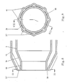
- the downstream end 36 of the combustion chamber 5 has indentations 39 for forming jet openings 37, while the outer tube 23 is provided with bulges 41 for forming jet openings 37 '.
- Both the nozzle and the outer tube 23 have a circular cross-section. They are rotatably supported one inside the other.
- Figures 7, 9, 10 and 11 make it clear how large the range of variation of the possibilities of influence according to the invention is. Since the invention also includes exhaust gas recirculation, a wide variety of layers of flame, oxygen carrier gas and exhaust gas can be achieved.
- the oxygen carrier gas emerging from the gap sections 38 can also be used to influence the flame, specifically for cooling it.
- the gap width will be small compared to the diameter of the jet openings 37 and 37 'because the throughput through the gap section is difficult to adjust.
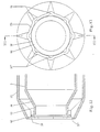
- FIGS. 12 and 13 differs from that according to FIGS. 8 and 9 above all in that a at the downstream end 36 of the combustion chamber 5, in the present case at the downstream end of the parallel-walled end section 40, is formed radial flange 42 is arranged, on the outer edge of which the outer tube 23 tapers.
- the transition between the end section 40 and the flange 42 is rounded for fluidic reasons. Due to the flange 42, the oxygen carrier gas jets occur at a radial distance from the base of the flame. This makes it easier to suck in an exhaust gas layer as an intermediate layer between the flame and the oxygen carrier gas jets, which likewise serves to optimize the flame length and NO x formation, and allows the intensity of the combustion step to be set.
- FIGS. 12 and 13 also show that the bulges 41, unlike in FIG. 8, grow out of the outer tube 23 with increasing width.
- the combustion chamber 5 with its downstream end 36 and possibly the end section 40 and the flange 42 is made in one piece from ceramic in the present case.
- the two parts can be arranged such that, as mentioned, there is longitudinal displacement in the region of the nozzle. This not only allows different thermal expansions, but also compensates for manufacturing tolerances. Furthermore, the components have the same wall thickness.
- FIGS. 14 and 15 show a high-speed burner which essentially corresponds to the embodiment according to FIGS. 12 and 13.
- the end portion of the outer tube 23 is aligned axially parallel, and it is instead of the flange 42, a widened portion 42 'with axially parallel outlet with the interposition of the end portion 40 at the downstream end 36 of the combustion chamber 5 is arranged.
- the embodiment according to FIGS. 14 and 15 is particularly favorable in terms of production technology for the ceramic material.
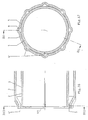
- FIGS. 16 and 17 show the application of the invention to a combustion chamber 5, which is designed with a constant cross-section up to its downstream end 2, that is, it does not belong to a high-speed burner.
- the combustion chamber 5 has a slot 44 which serves to avoid stress cracks.
- connection of the fuel lance 7 and the cylindrical section 12 to the nozzle 17 can also be done differently than by screwing or plugging on.
- the invention is also not limited to the two-stage burner shown, in which secondary air is supplied to the region of the narrowest cross section 6 of the combustion chamber 5. Rather, the invention can be readily applied to single-stage burners in which all of the combustion air is passed through the flame holder 3.
- the passage openings 4 can also be aligned at an angle to the surface of the flame holder in order to generate a swirl.
- the burner is suitable for any fluid or dusty fuel.
- the exemplary embodiments according to FIGS. 8 and 9 and 16 and 17 can be provided with a flange 40 corresponding to FIGS. 12 and 13.
- bulges 41 of the outer tube 23 can also be present instead of the indentations 39 of the combustion chamber.
- the arrangement of a flange 40 according to FIGS. 12 and 13 is also possible here.
- a flange 42 can be provided instead of the bulges 41 of the outer tube 23, bulges 39 of the combustion chamber 5 or of the section 40 and, if appropriate.
- the flange 42 can also have corresponding recesses in its edge.
Landscapes
- Engineering & Computer Science (AREA)
- Chemical & Material Sciences (AREA)
- Combustion & Propulsion (AREA)
- Mechanical Engineering (AREA)
- General Engineering & Computer Science (AREA)
- Pre-Mixing And Non-Premixing Gas Burner (AREA)
Priority Applications (1)
| Application Number | Priority Date | Filing Date | Title |
|---|---|---|---|
| AT89118554T ATE104416T1 (de) | 1988-10-12 | 1989-10-06 | Brenner, insbesondere hochgeschwindigkeitsbrenner. |
Applications Claiming Priority (4)
| Application Number | Priority Date | Filing Date | Title |
|---|---|---|---|
| DE3834762 | 1988-10-12 | ||
| DE19883834762 DE3834762A1 (de) | 1988-10-12 | 1988-10-12 | Hochgeschwindigkeitsbrenner |
| DE19883835381 DE3835381A1 (de) | 1988-10-18 | 1988-10-18 | Brenner |
| DE3835381 | 1988-10-18 |
Publications (2)
| Publication Number | Publication Date |
|---|---|
| EP0363834A1 true EP0363834A1 (fr) | 1990-04-18 |
| EP0363834B1 EP0363834B1 (fr) | 1994-04-13 |
Family
ID=25873170
Family Applications (1)
| Application Number | Title | Priority Date | Filing Date |
|---|---|---|---|
| EP89118554A Expired - Lifetime EP0363834B1 (fr) | 1988-10-12 | 1989-10-06 | Brûleur, particulièrement brûleur à haute vitesse |
Country Status (3)
| Country | Link |
|---|---|
| US (1) | US5055032A (fr) |
| EP (1) | EP0363834B1 (fr) |
| DE (1) | DE58907451D1 (fr) |
Cited By (4)
| Publication number | Priority date | Publication date | Assignee | Title |
|---|---|---|---|---|
| EP0471956A3 (en) * | 1990-08-23 | 1992-08-26 | Lbe Beheizungseinrichtungen Gmbh | Burner |
| RU2223907C2 (ru) * | 2002-03-26 | 2004-02-20 | Открытое акционерное общество "Всероссийский алюминиево-магниевый институт" | Устройство для сжигания водородсодержащего топлива в смеси хлорсодержащего газа и воздуха |
| WO2009047260A3 (fr) * | 2007-10-09 | 2010-01-14 | Ibs Industrie-Brenner-Systeme Gmbh | Brûleur pour four industriel |
| CN109357256A (zh) * | 2018-10-31 | 2019-02-19 | 北京动力机械研究所 | 一种用于冲压火箭型加热器的点火装置 |
Families Citing this family (30)
| Publication number | Priority date | Publication date | Assignee | Title |
|---|---|---|---|---|
| US5257926A (en) * | 1991-12-17 | 1993-11-02 | Gideon Drimer | Fast, safe, pyrogenic external torch assembly |
| DE69328300T2 (de) * | 1992-07-07 | 2000-11-30 | Maxon Corp., Muncie | Rohrbrenner |
| US5265409A (en) * | 1992-12-18 | 1993-11-30 | United Technologies Corporation | Uniform cooling film replenishment thermal liner assembly |
| US5323601A (en) * | 1992-12-21 | 1994-06-28 | United Technologies Corporation | Individually removable combustor liner panel for a gas turbine engine |
| US5291733A (en) * | 1993-02-08 | 1994-03-08 | General Electric Company | Liner mounting assembly |
| US5961316A (en) * | 1995-10-25 | 1999-10-05 | Weil-Mclain | Oil burner |
| US5971745A (en) * | 1995-11-13 | 1999-10-26 | Gas Research Institute | Flame ionization control apparatus and method |
| US6179609B1 (en) * | 1998-08-05 | 2001-01-30 | Persys Technology Ltd. | Compact external torch assembly for semiconductor processing |
| US6589600B1 (en) * | 1999-06-30 | 2003-07-08 | General Electric Company | Turbine engine component having enhanced heat transfer characteristics and method for forming same |
| US6299433B1 (en) | 1999-11-05 | 2001-10-09 | Gas Research Institute | Burner control |
| US6702572B2 (en) * | 2001-08-20 | 2004-03-09 | John Zink Company, Llc | Ultra-stable flare pilot and methods |
| US7028622B2 (en) | 2003-04-04 | 2006-04-18 | Maxon Corporation | Apparatus for burning pulverized solid fuels with oxygen |
| US7241135B2 (en) * | 2004-11-18 | 2007-07-10 | Honeywell International Inc. | Feedback control for modulating gas burner |
| US7464537B2 (en) * | 2005-04-04 | 2008-12-16 | United Technologies Corporation | Heat transfer enhancement features for a tubular wall combustion chamber |
| US20070107642A1 (en) * | 2005-11-14 | 2007-05-17 | Johnson J E | Fuel ignition systems |
| US7591648B2 (en) * | 2007-09-13 | 2009-09-22 | Maxon Corporation | Burner apparatus |
| US8622737B2 (en) | 2008-07-16 | 2014-01-07 | Robert S. Babington | Perforated flame tube for a liquid fuel burner |
| US9587823B2 (en) | 2009-03-25 | 2017-03-07 | Wallace Horn | Laminar flow jets |
| US8087928B2 (en) * | 2009-03-25 | 2012-01-03 | Horn Wallace E | Laminar flow jets |
| IT1397192B1 (it) * | 2009-12-01 | 2013-01-04 | Danieli Off Mecc | Bruciatore industriale e relativo processo di combustione per forni di trattamento termico. |
| EP2864702B1 (fr) * | 2012-06-22 | 2017-02-22 | Ferndale Investments Pty Ltd | Chalumeau de chauffe |
| JP6395619B2 (ja) * | 2015-01-16 | 2018-09-26 | 大阪瓦斯株式会社 | 直進炎型ガスバーナ |
| WO2017056318A1 (fr) * | 2015-10-02 | 2017-04-06 | 大阪瓦斯株式会社 | Brûleur à régénération et four métallique |
| FI127083B (en) * | 2015-10-30 | 2017-11-15 | Outotec Finland Oy | Burner and fines feeder for burner |
| CN105953241A (zh) * | 2016-05-30 | 2016-09-21 | 江苏沃尔特环保有限公司 | 一种高效燃烧的内燃式沼气焚烧火炬 |
| CN105953242A (zh) * | 2016-05-30 | 2016-09-21 | 江苏沃尔特环保有限公司 | 一种内燃式沼气焚烧火炬 |
| US11287128B2 (en) | 2019-01-03 | 2022-03-29 | Carrier Corporation | Inward fired low NOX premix burner |
| EP3864345B1 (fr) * | 2019-06-21 | 2025-11-05 | Econova GmbH | Brûleur pour réduire les émissions de nox et procédé permettant de faire fonctionner le brûleur |
| EP4033149A1 (fr) * | 2021-01-22 | 2022-07-27 | L'air Liquide, Societe Anonyme Pour L'etude Et L'exploitation Des Procedes Georges Claude | Surveillance de matières combustibles dans un flux gazeux |
| US12158268B2 (en) * | 2021-06-08 | 2024-12-03 | Forney Corporation | High-capacity igniter |
Citations (3)
| Publication number | Priority date | Publication date | Assignee | Title |
|---|---|---|---|---|
| US2853284A (en) * | 1954-06-10 | 1958-09-23 | Mitchell Co John E | High velocity heater |
| DE1551815A1 (de) * | 1967-08-17 | 1970-03-26 | Polysius Ag | Gasbrenner |
| DE2129357B2 (de) * | 1971-03-03 | 1978-11-30 | Tokyo Gas Co. Ltd., Tokio | Brennvorrichtung für gasförmigen Brennstoff |
Family Cites Families (14)
| Publication number | Priority date | Publication date | Assignee | Title |
|---|---|---|---|---|
| US2417835A (en) * | 1936-09-25 | 1947-03-25 | Harry H Moore | Combustion device |
| US2499207A (en) * | 1945-12-22 | 1950-02-28 | John J Wolfersperger | Pressure-type burner and method of burning fuel |
| US2485207A (en) * | 1946-09-06 | 1949-10-18 | Gilbert & Barker Mfg Co | Air control for tubular combustion chambers of oil burners |
| NL72931C (fr) * | 1948-02-21 | |||
| BE501690A (fr) * | 1950-03-07 | |||
| GB715909A (en) * | 1952-02-01 | 1954-09-22 | Rolls Royce | Improvements in or relating to combustion equipment of gas-turbine engines |
| GB1010338A (en) * | 1962-09-11 | 1965-11-17 | Lucas Industries Ltd | Means for supporting the downstream end of a combustion chamber in a gas turbine engine |
| US3574508A (en) * | 1968-04-15 | 1971-04-13 | Maxon Premix Burner Co Inc | Internally fired industrial gas burner |
| US3738792A (en) * | 1972-02-11 | 1973-06-12 | Selas Corp Of America | Industrial burner |
| DE2457963A1 (de) * | 1974-12-07 | 1976-06-16 | Interliz Anstalt | Heissgasgenerator |
| US4008568A (en) * | 1976-03-01 | 1977-02-22 | General Motors Corporation | Combustor support |
| US4726763A (en) * | 1982-09-24 | 1988-02-23 | Gte Products Corporation | Dual insulated ceramic burner |
| DE3422229C2 (de) * | 1984-06-15 | 1986-06-05 | WS Wärmeprozesstechnik GmbH, 7015 Korntal-Münchingen | Industriebrenner für gasförmige oder flüssige Brennstoffe |
| CH670297A5 (fr) * | 1986-02-13 | 1989-05-31 | Schilling Siegfried W |
-
1989
- 1989-10-06 DE DE58907451T patent/DE58907451D1/de not_active Expired - Fee Related
- 1989-10-06 EP EP89118554A patent/EP0363834B1/fr not_active Expired - Lifetime
- 1989-10-12 US US07/420,563 patent/US5055032A/en not_active Expired - Fee Related
Patent Citations (3)
| Publication number | Priority date | Publication date | Assignee | Title |
|---|---|---|---|---|
| US2853284A (en) * | 1954-06-10 | 1958-09-23 | Mitchell Co John E | High velocity heater |
| DE1551815A1 (de) * | 1967-08-17 | 1970-03-26 | Polysius Ag | Gasbrenner |
| DE2129357B2 (de) * | 1971-03-03 | 1978-11-30 | Tokyo Gas Co. Ltd., Tokio | Brennvorrichtung für gasförmigen Brennstoff |
Cited By (4)
| Publication number | Priority date | Publication date | Assignee | Title |
|---|---|---|---|---|
| EP0471956A3 (en) * | 1990-08-23 | 1992-08-26 | Lbe Beheizungseinrichtungen Gmbh | Burner |
| RU2223907C2 (ru) * | 2002-03-26 | 2004-02-20 | Открытое акционерное общество "Всероссийский алюминиево-магниевый институт" | Устройство для сжигания водородсодержащего топлива в смеси хлорсодержащего газа и воздуха |
| WO2009047260A3 (fr) * | 2007-10-09 | 2010-01-14 | Ibs Industrie-Brenner-Systeme Gmbh | Brûleur pour four industriel |
| CN109357256A (zh) * | 2018-10-31 | 2019-02-19 | 北京动力机械研究所 | 一种用于冲压火箭型加热器的点火装置 |
Also Published As
| Publication number | Publication date |
|---|---|
| DE58907451D1 (de) | 1994-05-19 |
| US5055032A (en) | 1991-10-08 |
| EP0363834B1 (fr) | 1994-04-13 |
Similar Documents
| Publication | Publication Date | Title |
|---|---|---|
| EP0363834B1 (fr) | Brûleur, particulièrement brûleur à haute vitesse | |
| DE69306039T2 (de) | Verbrennungsverfahren mit niedrigem NOx-Gehalt und Brennervorrichtung zur Durchführung des Verfahrens | |
| DE2143012C3 (de) | Brenneranordnung bei einer Gasturbinen-Brennkammer | |
| DE60105913T2 (de) | WANDSTRAHLUNGSBRENNER MIT NIEDRIGER NOx-EMISSION | |
| EP1723369B1 (fr) | Bruleur a premelange et procede pour bruler un gaz pauvre | |
| DE69510395T2 (de) | Gasbrenner für Industrieöfen | |
| DE2747678A1 (de) | Treibstoffduese fuer gasturbinen | |
| EP1950494A1 (fr) | Chambre de combustion pour turbine à gaz | |
| EP0175875B1 (fr) | Brûleur à huile ou à gaz pour la génération de gaz à chaud | |
| DE4446842A1 (de) | Verfahren und Vorrichtung zum Zuleiten eines gasförmigen Brennstoffs in einen Vormischbrenner | |
| CH703655A1 (de) | Vormischbrenner für eine gasturbine. | |
| DE19607676A1 (de) | Brenner und mit mindestens einem Brenner betriebene Feuerungsanlage | |
| DE2839627C2 (de) | Gasbrenner | |
| EP0483554B1 (fr) | Procédé pour la réduction au minimum des émissions de NOx dans une combustion | |
| EP1062461B1 (fr) | Chambre de combustion et mode de fonctionnement d'une chambre de combustion | |
| DE2226939A1 (de) | Brenner | |
| EP2171354A2 (fr) | Brûleur | |
| AT406706B (de) | Brenner für gas- und ölheizkessel | |
| EP0864812A2 (fr) | Dispositif de mélange pour brûleur à gaz et à huile | |
| DE10237604B4 (de) | Nachverbrennungseinrichtung mit einem Brenner | |
| DE19824719C2 (de) | Brenner, insbesondere Ölbrenner | |
| DE4130922C2 (de) | Brenner für Hochtemperaturprozesse sowie Verfahren zum Betreiben des Brenners | |
| DE102020108810B4 (de) | Brennerdüse, Brenner mit einer Brennerdüse und Ofen mit einem Brenner | |
| DE3834762A1 (de) | Hochgeschwindigkeitsbrenner | |
| AT406795B (de) | Brenner für gas- und ölheizungskessel |
Legal Events
| Date | Code | Title | Description |
|---|---|---|---|
| PUAI | Public reference made under article 153(3) epc to a published international application that has entered the european phase |
Free format text: ORIGINAL CODE: 0009012 |
|
| AK | Designated contracting states |
Kind code of ref document: A1 Designated state(s): AT BE DE ES FR GB IT NL |
|
| 17P | Request for examination filed |
Effective date: 19900526 |
|
| 17Q | First examination report despatched |
Effective date: 19910819 |
|
| GRAA | (expected) grant |
Free format text: ORIGINAL CODE: 0009210 |
|
| AK | Designated contracting states |
Kind code of ref document: B1 Designated state(s): AT BE DE ES FR GB IT NL |
|
| PG25 | Lapsed in a contracting state [announced via postgrant information from national office to epo] |
Ref country code: ES Free format text: THE PATENT HAS BEEN ANNULLED BY A DECISION OF A NATIONAL AUTHORITY Effective date: 19940413 Ref country code: BE Effective date: 19940413 |
|
| REF | Corresponds to: |
Ref document number: 104416 Country of ref document: AT Date of ref document: 19940415 Kind code of ref document: T |
|
| REF | Corresponds to: |
Ref document number: 58907451 Country of ref document: DE Date of ref document: 19940519 |
|
| ITF | It: translation for a ep patent filed | ||
| GBT | Gb: translation of ep patent filed (gb section 77(6)(a)/1977) |
Effective date: 19940708 |
|
| ET | Fr: translation filed | ||
| PG25 | Lapsed in a contracting state [announced via postgrant information from national office to epo] |
Ref country code: AT Effective date: 19941006 |
|
| PLBE | No opposition filed within time limit |
Free format text: ORIGINAL CODE: 0009261 |
|
| STAA | Information on the status of an ep patent application or granted ep patent |
Free format text: STATUS: NO OPPOSITION FILED WITHIN TIME LIMIT |
|
| 26N | No opposition filed | ||
| PGFP | Annual fee paid to national office [announced via postgrant information from national office to epo] |
Ref country code: GB Payment date: 20000915 Year of fee payment: 12 |
|
| PGFP | Annual fee paid to national office [announced via postgrant information from national office to epo] |
Ref country code: NL Payment date: 20000925 Year of fee payment: 12 |
|
| PGFP | Annual fee paid to national office [announced via postgrant information from national office to epo] |
Ref country code: FR Payment date: 20001012 Year of fee payment: 12 |
|
| PG25 | Lapsed in a contracting state [announced via postgrant information from national office to epo] |
Ref country code: GB Free format text: LAPSE BECAUSE OF NON-PAYMENT OF DUE FEES Effective date: 20011006 |
|
| REG | Reference to a national code |
Ref country code: GB Ref legal event code: IF02 |
|
| PG25 | Lapsed in a contracting state [announced via postgrant information from national office to epo] |
Ref country code: NL Free format text: LAPSE BECAUSE OF NON-PAYMENT OF DUE FEES Effective date: 20020501 |
|
| GBPC | Gb: european patent ceased through non-payment of renewal fee |
Effective date: 20011006 |
|
| PG25 | Lapsed in a contracting state [announced via postgrant information from national office to epo] |
Ref country code: FR Free format text: LAPSE BECAUSE OF NON-PAYMENT OF DUE FEES Effective date: 20020628 |
|
| NLV4 | Nl: lapsed or anulled due to non-payment of the annual fee |
Effective date: 20020501 |
|
| REG | Reference to a national code |
Ref country code: FR Ref legal event code: ST |
|
| PG25 | Lapsed in a contracting state [announced via postgrant information from national office to epo] |
Ref country code: IT Free format text: LAPSE BECAUSE OF NON-PAYMENT OF DUE FEES;WARNING: LAPSES OF ITALIAN PATENTS WITH EFFECTIVE DATE BEFORE 2007 MAY HAVE OCCURRED AT ANY TIME BEFORE 2007. THE CORRECT EFFECTIVE DATE MAY BE DIFFERENT FROM THE ONE RECORDED. Effective date: 20051006 |
|
| PGFP | Annual fee paid to national office [announced via postgrant information from national office to epo] |
Ref country code: DE Payment date: 20061023 Year of fee payment: 18 |
|
| PG25 | Lapsed in a contracting state [announced via postgrant information from national office to epo] |
Ref country code: DE Free format text: LAPSE BECAUSE OF NON-PAYMENT OF DUE FEES Effective date: 20080501 |