EP0363902A2 - Method of detecting wear of cutting tool - Google Patents
Method of detecting wear of cutting tool Download PDFInfo
- Publication number
- EP0363902A2 EP0363902A2 EP89118807A EP89118807A EP0363902A2 EP 0363902 A2 EP0363902 A2 EP 0363902A2 EP 89118807 A EP89118807 A EP 89118807A EP 89118807 A EP89118807 A EP 89118807A EP 0363902 A2 EP0363902 A2 EP 0363902A2
- Authority
- EP
- European Patent Office
- Prior art keywords
- cutting tool
- workpiece
- contact resistance
- cutting
- wear
- Prior art date
- Legal status (The legal status is an assumption and is not a legal conclusion. Google has not performed a legal analysis and makes no representation as to the accuracy of the status listed.)
- Granted
Links
Images


Classifications
-
- B—PERFORMING OPERATIONS; TRANSPORTING
- B23—MACHINE TOOLS; METAL-WORKING NOT OTHERWISE PROVIDED FOR
- B23Q—DETAILS, COMPONENTS, OR ACCESSORIES FOR MACHINE TOOLS, e.g. ARRANGEMENTS FOR COPYING OR CONTROLLING; MACHINE TOOLS IN GENERAL CHARACTERISED BY THE CONSTRUCTION OF PARTICULAR DETAILS OR COMPONENTS; COMBINATIONS OR ASSOCIATIONS OF METAL-WORKING MACHINES, NOT DIRECTED TO A PARTICULAR RESULT
- B23Q15/00—Automatic control or regulation of feed movement, cutting velocity or position of tool or work
- B23Q15/007—Automatic control or regulation of feed movement, cutting velocity or position of tool or work while the tool acts upon the workpiece
- B23Q15/16—Compensation for wear of the tool
-
- G—PHYSICS
- G05—CONTROLLING; REGULATING
- G05B—CONTROL OR REGULATING SYSTEMS IN GENERAL; FUNCTIONAL ELEMENTS OF SUCH SYSTEMS; MONITORING OR TESTING ARRANGEMENTS FOR SUCH SYSTEMS OR ELEMENTS
- G05B19/00—Program-control systems
- G05B19/02—Program-control systems electric
- G05B19/18—Numerical control [NC], i.e. automatically operating machines, in particular machine tools, e.g. in a manufacturing environment, so as to execute positioning, movement or co-ordinated operations by means of program data in numerical form
- G05B19/406—Numerical control [NC], i.e. automatically operating machines, in particular machine tools, e.g. in a manufacturing environment, so as to execute positioning, movement or co-ordinated operations by means of program data in numerical form characterised by monitoring or safety
- G05B19/4065—Monitoring tool breakage, life or condition
-
- B—PERFORMING OPERATIONS; TRANSPORTING
- B23—MACHINE TOOLS; METAL-WORKING NOT OTHERWISE PROVIDED FOR
- B23Q—DETAILS, COMPONENTS, OR ACCESSORIES FOR MACHINE TOOLS, e.g. ARRANGEMENTS FOR COPYING OR CONTROLLING; MACHINE TOOLS IN GENERAL CHARACTERISED BY THE CONSTRUCTION OF PARTICULAR DETAILS OR COMPONENTS; COMBINATIONS OR ASSOCIATIONS OF METAL-WORKING MACHINES, NOT DIRECTED TO A PARTICULAR RESULT
- B23Q17/00—Arrangements for observing, indicating or measuring on machine tools
- B23Q17/09—Arrangements for observing, indicating or measuring on machine tools for indicating or measuring cutting pressure or for determining cutting-tool condition, e.g. cutting ability, load on tool
-
- G—PHYSICS
- G05—CONTROLLING; REGULATING
- G05B—CONTROL OR REGULATING SYSTEMS IN GENERAL; FUNCTIONAL ELEMENTS OF SUCH SYSTEMS; MONITORING OR TESTING ARRANGEMENTS FOR SUCH SYSTEMS OR ELEMENTS
- G05B2219/00—Program-control systems
- G05B2219/30—Nc systems
- G05B2219/37—Measurements
- G05B2219/37256—Wear, tool wear
Definitions
- the present invention relates to a method of measuring wear of a cutting tool during cutting work.
- acoustic emission In a generally known method of measuring wear of a cutting tool during cutting work, acoustic emission (AE) is utilized as disclosed in Japanese Patent Laying-Open Gazette No. 13858/1982, for example.
- This AE method is adapted to detect acoustic emission generated during cutting work upon breaking of a cutting tool by an AE sensor, thereby to measure wear thereof.
- it is impossible to accurately detect only such acoustic emission since various noises are made on the jobsite of actual cutting work.
- the AE method is insufficient in accuracy.
- Another conventional method is adapted to measure wear by measuring cutting force caused in cutting work, as disclosed in Japanese Patent Laying-Open Gazette No. 5252/1980 or 218053/1987, for example.
- cutting force is varied with configurations of cut positions of workpieces etc.
- this method is not employable unless workpieces are regularly cut in the same configuration.
- a cutting tool is formed of a material containing a radioactive isotope such as radioactive cobalt, and reduction of the radioactive isotope is measured through change in radioactivity, thereby to detect wear of the cutting tool.
- a radioactive isotope such as radioactive cobalt
- An object of the present invention is to provide a method which can accurately and stably detect wear of a cutting tool with no influence by disturbance factors such as the work environment of cutting work, dispersion in hardness or configuration of workpieces, etc.
- the inventive method of detecting wear comprises steps of measuring contact resistance between a cutting tool and a workpiece and detecting wear of the cutting tool from the measured contact resistance.
- the material for the cutting tool is not particularly restricted in the present invention, while an insert may be prepared from cemented carbide or coated cemented carbide, for example.
- contact resistance between a cutting tool and a workpiece may be measured by a general method of measuring electrical resistance such as that called a four terminal method, for example.
- Such contact resistance which is caused since a current fed from a wide passage is abruptly narrowed at the contact point, is called spreading resistance.
- thermoelectromotive force is generated between the cutting tool and the workpiece.
- potential difference Em measured between the cutting tool and the workpiece includes such thermoelectromotive force Et.
- contact resistance R between the cutting tool and the workpiece can be evaluated as follows: where I represents the current flowing between the cutting tool and the workpiece.
- thermoelectromotive force can be detected by interrupting the current flowing between the cutting tool and the workpiece and measuring potential difference developed across the same.
- a preferred embodiment of the present invention comprises steps of feeding a current between a cutting tool and a workpiece to evaluate potential difference developed across the cutting tool and the workpiece and the current value, interrupting the current flowing between the cutting tool and the workpiece to evaluate thermoelectromotive force generated by contact between the cutting tool and the workpiece, measuring contact resistance between the cutting tool and the workpiece by subtracting the thermoelectromotive force from the measured potential difference and dividing the result by the current value, and detecting wear of the cutting tool from the measured contact resistance.
- the wear of the cutting tool can be stably and accurately measured during cutting work on the workpiece with an extremely simple apparatus.
- Fig. 1 is a circuit diagram showing an embodiment of the inventive method of detecting wear.
- a workpiece 1 is cut by an insert 2, which serves as a cutting tool.
- the workpiece 1 is in contact with the insert 2 at a contact part 3.
- a power source 4 is connected between the insert 2 and the workpiece 1, and this power source 4 is connected to the workpiece 1 through an ampere meter 5 and a switch 7.
- a voltmeter 6 is so connected as to measure potential difference between the insert 2 and the workpiece 1.
- the switch 7 is so closed that a current from the power source 4 flows between the workpiece 1 and the insert 2.
- the ampere meter 5 reads the current value at this time, and the voltmeter 6 reads the potential difference between the workpiece 1 and the insert 2.
- the switch 7 is opened to interrupt the current flowing between the workpiece 1 and the insert 2.
- the voltmeter 6 reads the potential difference between the workpiece 1 and the insert 2, thereby to evaluate thermoelectromotive force Et.
- Contact resistance R can be evaluated by subtracting the thermoelectromotive force Et from potential difference Em developed across the workpiece 1 and the insert 2 when the current flows from the power source 4, and dividing the result by the current value I read by the ampere meter 5.
- inserts were prepared from AC10 and ST15E of type No. TNMN160408 by Sumitomo Electric Industries, Ltd. to cut workpieces of S45C with holders of FN21R-44A, and relations between cutting length and contact resistance values were measured through the apparatus shown in Fig. 1. Cutting conditions were as follows: Cutting Velocity: 100 m/min. Feed Rate: 0.30 mm/rev. Depth of Cut: 2 mm.
- the insert of AC10 was formed of cemented carbide coated with aluminum oxide through TiC.
- the insert of ST15E was formed of general cemented carbide of grade P20 under ISO standards.
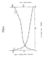
- Fig. 2 shows the relations between the contact resistance values and the cutting length thus measured. As obvious from Fig. 2, it is understood that an insert of coated cemented carbide exhibits a remarkable effect as compared with that of general cemented carbide.
- An insert prepared from AC10 of type No. CNMG120408N-UG by Sumitomo Electric Industries, Ltd. was employed to cut a workpiece of S45C with a holder of PCLNR2525-43.
- the insert of AC10 was formed of cemented carbide coated with aluminum oxide through TiC, similarly to the above.
- Cutting conditions were as follows: Cutting Velocity: 250 m/min. Feed Rate: 0.36 mm/rev. Depth of Cut: 2 mm
- a direct current of 5 A was fed between the insert and the workpiece by an apparatus which was based on a principle similar to that of the apparatus shown in Fig. 1, to measure potential difference.
- a switch of the apparatus was opened every contact period to measure thermoelectromotive force, thereby to evaluate potential difference developed during cutting work.
- Fig. 3 is a chart showing change of the potential difference thus measured. As shown in Fig. 3, the potential difference was abruptly reduced every constant period, in correspondence to opening of the switch 7. Electromotive force Et measured when the switch 7 was turned off corresponds to the thermoelectromotive force.
- Fig. 4 shows the change of the contact resistance thus evaluated.
- FIG. 4 shows the results thus obtained. As obvious from Fig. 4, it is understood that there are constant relations between the contact resistance values and the flank wear values. Thus, wear of an insert can be evaluated by measuring contact resistance according to the present invention.
Landscapes
- Engineering & Computer Science (AREA)
- Human Computer Interaction (AREA)
- Manufacturing & Machinery (AREA)
- Physics & Mathematics (AREA)
- General Physics & Mathematics (AREA)
- Automation & Control Theory (AREA)
- Mechanical Engineering (AREA)
- Measurement Of Length, Angles, Or The Like Using Electric Or Magnetic Means (AREA)
- Machine Tool Sensing Apparatuses (AREA)
- Cutting Tools, Boring Holders, And Turrets (AREA)
Abstract
Description
- The present invention relates to a method of measuring wear of a cutting tool during cutting work.
- In a generally known method of measuring wear of a cutting tool during cutting work, acoustic emission (AE) is utilized as disclosed in Japanese Patent Laying-Open Gazette No. 13858/1982, for example. This AE method is adapted to detect acoustic emission generated during cutting work upon breaking of a cutting tool by an AE sensor, thereby to measure wear thereof. However, it is impossible to accurately detect only such acoustic emission since various noises are made on the jobsite of actual cutting work. Thus, the AE method is insufficient in accuracy.
- Another conventional method is adapted to measure wear by measuring cutting force caused in cutting work, as disclosed in Japanese Patent Laying-Open Gazette No. 5252/1980 or 218053/1987, for example. However, such cutting force is varied with configurations of cut positions of workpieces etc. Thus, this method is not employable unless workpieces are regularly cut in the same configuration.
- In still another conventional method, a cutting tool is formed of a material containing a radioactive isotope such as radioactive cobalt, and reduction of the radioactive isotope is measured through change in radioactivity, thereby to detect wear of the cutting tool. However, it is clear that such a method is unpreferable in consideration of sanitation of the work environment.
- An object of the present invention is to provide a method which can accurately and stably detect wear of a cutting tool with no influence by disturbance factors such as the work environment of cutting work, dispersion in hardness or configuration of workpieces, etc.
- The inventive method of detecting wear comprises steps of measuring contact resistance between a cutting tool and a workpiece and detecting wear of the cutting tool from the measured contact resistance.
- The material for the cutting tool is not particularly restricted in the present invention, while an insert may be prepared from cemented carbide or coated cemented carbide, for example.
- According to the present invention, contact resistance between a cutting tool and a workpiece may be measured by a general method of measuring electrical resistance such as that called a four terminal method, for example.
- The principle of the present invention, in which wear can be detected by measuring contact resistance, is now described. Assuming that a represents the radius of a contact point between two conductors A and B, contact resistance R between the conductors A and B is expressed as follows:
R =
where ρ represents resistivity. - Such contact resistance, which is caused since a current fed from a wide passage is abruptly narrowed at the contact point, is called spreading resistance.
- As cutting work progresses to increase wear of a cutting tool, the area of a contact part between the cutting tool and a workpiece is increased. Thus, contact resistance between the cutting tool and the workpiece is reduced. Therefore, the wear of the cutting tool can be evaluated by measuring the contact resistance.
- In general, the contact part between the cutting tool and the workpiece is heated to an extremely high temperature of 500 to 1000°C during the cutting work. Therefore, thermoelectromotive force is generated between the cutting tool and the workpiece. Thus, potential difference Em measured between the cutting tool and the workpiece includes such thermoelectromotive force Et. Hence, contact resistance R between the cutting tool and the workpiece can be evaluated as follows:

- The aforementioned thermoelectromotive force can be detected by interrupting the current flowing between the cutting tool and the workpiece and measuring potential difference developed across the same.
- A preferred embodiment of the present invention comprises steps of feeding a current between a cutting tool and a workpiece to evaluate potential difference developed across the cutting tool and the workpiece and the current value, interrupting the current flowing between the cutting tool and the workpiece to evaluate thermoelectromotive force generated by contact between the cutting tool and the workpiece, measuring contact resistance between the cutting tool and the workpiece by subtracting the thermoelectromotive force from the measured potential difference and dividing the result by the current value, and detecting wear of the cutting tool from the measured contact resistance.
- According to the inventive method, the wear of the cutting tool can be stably and accurately measured during cutting work on the workpiece with an extremely simple apparatus.
- These and other objects, features, aspects and advantages of the present invention will become more apparent from the following detailed description of the present invention when taken in conjunction with the accompanying drawings.
-
- Fig. 1 is a circuit diagram showing an embodiment of the inventive detecting method;
- Fig. 2 illustrates relations between contact resistance values and cut distances in the embodiment of the present invention;
- Fig. 3 is a chart showing change in potential difference in the embodiment of the present invention; and
- Fig. 4 is a graph showing relations between contact resistance and flank wear.
- Fig. 1 is a circuit diagram showing an embodiment of the inventive method of detecting wear. Referring to Fig. 1, a workpiece 1 is cut by an
insert 2, which serves as a cutting tool. The workpiece 1 is in contact with theinsert 2 at acontact part 3. Apower source 4 is connected between theinsert 2 and the workpiece 1, and thispower source 4 is connected to the workpiece 1 through anampere meter 5 and aswitch 7. Further, avoltmeter 6 is so connected as to measure potential difference between theinsert 2 and the workpiece 1. Theswitch 7 is so closed that a current from thepower source 4 flows between the workpiece 1 and theinsert 2. Theampere meter 5 reads the current value at this time, and thevoltmeter 6 reads the potential difference between the workpiece 1 and theinsert 2. - Then the
switch 7 is opened to interrupt the current flowing between the workpiece 1 and theinsert 2. In this state, thevoltmeter 6 reads the potential difference between the workpiece 1 and theinsert 2, thereby to evaluate thermoelectromotive force Et. Contact resistance R can be evaluated by subtracting the thermoelectromotive force Et from potential difference Em developed across the workpiece 1 and theinsert 2 when the current flows from thepower source 4, and dividing the result by the current value I read by theampere meter 5. - Examples of inserts were prepared from AC10 and ST15E of type No. TNMN160408 by Sumitomo Electric Industries, Ltd. to cut workpieces of S45C with holders of FN21R-44A, and relations between cutting length and contact resistance values were measured through the apparatus shown in Fig. 1. Cutting conditions were as follows:
Cutting Velocity: 100 m/min.
Feed Rate: 0.30 mm/rev.
Depth of Cut: 2 mm
The insert of AC10 was formed of cemented carbide coated with aluminum oxide through TiC. The insert of ST15E was formed of general cemented carbide of grade P20 under ISO standards. - Fig. 2 shows the relations between the contact resistance values and the cutting length thus measured. As obvious from Fig. 2, it is understood that an insert of coated cemented carbide exhibits a remarkable effect as compared with that of general cemented carbide.
- An insert prepared from AC10 of type No. CNMG120408N-UG by Sumitomo Electric Industries, Ltd. was employed to cut a workpiece of S45C with a holder of PCLNR2525-43. The insert of AC10 was formed of cemented carbide coated with aluminum oxide through TiC, similarly to the above. Cutting conditions were as follows:
Cutting Velocity: 250 m/min.
Feed Rate: 0.36 mm/rev.
Depth of Cut: 2 mm - A direct current of 5 A was fed between the insert and the workpiece by an apparatus which was based on a principle similar to that of the apparatus shown in Fig. 1, to measure potential difference. In more concrete terms, a switch of the apparatus was opened every contact period to measure thermoelectromotive force, thereby to evaluate potential difference developed during cutting work.
- Fig. 3 is a chart showing change of the potential difference thus measured. As shown in Fig. 3, the potential difference was abruptly reduced every constant period, in correspondence to opening of the
switch 7. Electromotive force Et measured when theswitch 7 was turned off corresponds to the thermoelectromotive force. - Thus, the potential difference was evaluated while measuring the thermoelectromotive force Et, to evaluate contact resistance.
- Fig. 4 shows the change of the contact resistance thus evaluated.
- An insert absolutely identical to that of the above embodiment was employed to cut a workpiece under the same conditions, thereby to evaluate flank wear every constant cutting period. Fig. 4 shows the results thus obtained. As obvious from Fig. 4, it is understood that there are constant relations between the contact resistance values and the flank wear values. Thus, wear of an insert can be evaluated by measuring contact resistance according to the present invention.
- Although the present invention has been described and illustrated in detail, it is clearly understood that the same is by way of illustration and example only and is not to be taken by way of limitation, the spirit and scope of the present invention being limited only by the terms of the appended claims.
Claims (5)
measuring contact resistance between said cutting tool and said workpiece; and
detecting wear of said cutting tool from said measured contact resistance.
feeding a current between said cutting tool and said workpiece to evaluate potential difference developed across said cutting tool and said workpiece and the value of said current;
interrupting said current flowing between said cutting tool and said workpiece to evaluate thermoelectromotive force generated by contact between said cutting tool and said workpiece;
subtracting said thermoelectromotive force from said potential difference and dividing the result by said current value thereby to measure contact resistance between said cutting tool and said workpiece; and
detecting wear of said cutting tool from said measured contact resistance.
Applications Claiming Priority (2)
| Application Number | Priority Date | Filing Date | Title |
|---|---|---|---|
| JP63259850A JPH02106254A (en) | 1988-10-14 | 1988-10-14 | Tool wear detection method |
| JP259850/88 | 1988-10-14 |
Publications (3)
| Publication Number | Publication Date |
|---|---|
| EP0363902A2 true EP0363902A2 (en) | 1990-04-18 |
| EP0363902A3 EP0363902A3 (en) | 1993-09-22 |
| EP0363902B1 EP0363902B1 (en) | 1995-07-19 |
Family
ID=17339845
Family Applications (1)
| Application Number | Title | Priority Date | Filing Date |
|---|---|---|---|
| EP89118807A Expired - Lifetime EP0363902B1 (en) | 1988-10-14 | 1989-10-10 | Method of detecting wear of cutting tool |
Country Status (5)
| Country | Link |
|---|---|
| US (1) | US5030920A (en) |
| EP (1) | EP0363902B1 (en) |
| JP (1) | JPH02106254A (en) |
| KR (1) | KR930004184B1 (en) |
| DE (1) | DE68923521T2 (en) |
Cited By (3)
| Publication number | Priority date | Publication date | Assignee | Title |
|---|---|---|---|---|
| FR2733064A1 (en) * | 1995-04-14 | 1996-10-18 | Dufour Francois Et Fils | METHOD AND DEVICE FOR MACHINE TOOL MACHINING CONTROL |
| EP0939292A1 (en) * | 1998-02-27 | 1999-09-01 | Sollac | Device and method for continuously measuring the wear of a wall of a metallurgical vessel |
| DE19813033A1 (en) * | 1998-03-25 | 1999-09-30 | Gottzmann Andreas | Device for detecting plate fractures and wear in indexable insert for metalworking machine |
Families Citing this family (11)
| Publication number | Priority date | Publication date | Assignee | Title |
|---|---|---|---|---|
| JPH06262492A (en) * | 1993-03-17 | 1994-09-20 | Fanuc Ltd | Life control method for tool by estimating disturbance load |
| KR100201020B1 (en) * | 1994-03-11 | 1999-06-15 | 모리시타 요이찌 | NC control fine machining method with computer simulation and apparatus used in this method |
| AU3310297A (en) * | 1996-06-26 | 1998-01-14 | Gleason Works, The | Detecting tool wear by thermal monitoring of workpiece |
| US6758640B2 (en) * | 2000-10-11 | 2004-07-06 | Fuji Seiko Limited | Method and apparatus for controlling movement of cutting blade and workpiece |
| EP2476511B1 (en) * | 2011-01-14 | 2013-03-27 | ARTIS GmbH | Device and method for monitoring a machine tool |
| DE102014204833A1 (en) * | 2014-03-14 | 2015-09-17 | Werner Kluft | Device, machine tool and method for measuring and monitoring tools or workpieces |
| US10184775B2 (en) * | 2016-04-20 | 2019-01-22 | Shawn Lause | Standard tool diameter gage |
| US10935359B2 (en) | 2016-04-20 | 2021-03-02 | Shawn Thomas Lause | Standard tool diameter gage |
| CN113030183B (en) * | 2021-03-01 | 2023-04-07 | 深圳市金洲精工科技股份有限公司 | Drill coating falling detection method |
| DE102021110855A1 (en) | 2021-04-28 | 2022-11-03 | Herrenknecht Aktiengesellschaft | Cutting wheel for a tunnel boring machine |
| CN114800039B (en) * | 2022-04-08 | 2023-03-14 | 山东大学 | Characteristic strengthening method and system for on-line monitoring of state of milling cutter of thin-wall part |
Family Cites Families (10)
| Publication number | Priority date | Publication date | Assignee | Title |
|---|---|---|---|---|
| GB1259272A (en) * | 1967-11-27 | 1972-01-05 | ||
| US4207567A (en) * | 1977-11-17 | 1980-06-10 | The Valeron Corporation | Broken, chipped and worn tool detector |
| JPS5820743B2 (en) * | 1978-06-28 | 1983-04-25 | トヨタ自動車株式会社 | Tool abnormality detection method for machine tools |
| JPS5536457A (en) * | 1978-09-08 | 1980-03-14 | Ajinomoto Co Inc | Amino acid infusion |
| JPS57138558A (en) * | 1981-02-16 | 1982-08-26 | Mitsubishi Heavy Ind Ltd | Detecting device of contact of tool with work, as well defect in tool |
| JPS5832825Y2 (en) * | 1981-08-20 | 1983-07-21 | 株式会社 阪村機械製作所 | Dice exchange device |
| US4694686A (en) * | 1984-06-18 | 1987-09-22 | Borg-Warner Corporation | Cutting tool wear monitor |
| SE452911B (en) * | 1984-07-06 | 1987-12-21 | Birger Alvelid | PROCEDURE FOR THE MANUFACTURING OF THE MECHANICAL COMPONENTS, ALSO DIFFICULT MECHANICAL COMPONENTS |
| JPS62218053A (en) * | 1986-03-18 | 1987-09-25 | Ishikawajima Harima Heavy Ind Co Ltd | Tool breakage detection device |
| US4831365A (en) * | 1988-02-05 | 1989-05-16 | General Electric Company | Cutting tool wear detection apparatus and method |
-
1988
- 1988-10-14 JP JP63259850A patent/JPH02106254A/en active Pending
-
1989
- 1989-10-10 DE DE68923521T patent/DE68923521T2/en not_active Expired - Fee Related
- 1989-10-10 EP EP89118807A patent/EP0363902B1/en not_active Expired - Lifetime
- 1989-10-13 US US07/421,612 patent/US5030920A/en not_active Expired - Fee Related
- 1989-10-14 KR KR1019890014728A patent/KR930004184B1/en not_active Expired - Fee Related
Non-Patent Citations (2)
| Title |
|---|
| MECANIQUE MATERIAUX ELECTRICITE. nos. 301,302, Jan.- Feb. 1975, PARIS FR pages 34 - 36; B. ROUMESY ET AL: "Test rapide d'usinabilité par measure thermoélectrique" * |
| PROCEEDINGS OF THE INSTITUTION OF ELECTRICAL ENGINEERS. vol. 118, no. 2, February 1971, STEVENAGE GB pages 381 - 386; A. J. WILKINSON: "CONSTRICTION-RESISTANCE CONCEPT APPLIED TO WEAR MEASUREMENT OF METAL-CUTTING TOOLS" * |
Cited By (6)
| Publication number | Priority date | Publication date | Assignee | Title |
|---|---|---|---|---|
| FR2733064A1 (en) * | 1995-04-14 | 1996-10-18 | Dufour Francois Et Fils | METHOD AND DEVICE FOR MACHINE TOOL MACHINING CONTROL |
| EP0737903A3 (en) * | 1995-04-14 | 1996-11-13 | Etudes Realisations Representations Industrielles Et Commerciales | Method and device for monitoring machining on a machine-tool |
| EP0939292A1 (en) * | 1998-02-27 | 1999-09-01 | Sollac | Device and method for continuously measuring the wear of a wall of a metallurgical vessel |
| FR2775519A1 (en) * | 1998-02-27 | 1999-09-03 | Lorraine Laminage | DEVICE AND METHOD FOR CONTINUOUS MEASUREMENT OF THE WEAR OF A METALLURGICAL CONTAINER WALL |
| US6208128B1 (en) | 1998-02-27 | 2001-03-27 | Sollac | Apparatus and method of continuously measuring the wear of a wall of a metallurgical vessel |
| DE19813033A1 (en) * | 1998-03-25 | 1999-09-30 | Gottzmann Andreas | Device for detecting plate fractures and wear in indexable insert for metalworking machine |
Also Published As
| Publication number | Publication date |
|---|---|
| KR930004184B1 (en) | 1993-05-21 |
| DE68923521D1 (en) | 1995-08-24 |
| US5030920A (en) | 1991-07-09 |
| JPH02106254A (en) | 1990-04-18 |
| EP0363902B1 (en) | 1995-07-19 |
| EP0363902A3 (en) | 1993-09-22 |
| DE68923521T2 (en) | 1996-02-08 |
| KR900006075A (en) | 1990-05-07 |
Similar Documents
| Publication | Publication Date | Title |
|---|---|---|
| EP0363902A2 (en) | Method of detecting wear of cutting tool | |
| Mannan et al. | Monitoring and adaptive control of cutting process by means of motor power and current measurements | |
| Lan et al. | In-process tool fracture detection | |
| US3841149A (en) | Tool wear detector | |
| Brinksmeier | Prediction of tool fracture in drilling | |
| Kinoshita et al. | Study on wire-EDM: inprocess measurement of mechanical behaviour of electrode-wire | |
| EP0226631B1 (en) | Method and apparatus for editing particle produced electrical pulses | |
| JP2532259B2 (en) | Discharge position detector for wire electric discharge machine | |
| EP3085482B1 (en) | Wire electric discharge machine | |
| EP0468451A2 (en) | Method and apparatus for positioning first and second objects based on a potential difference | |
| US3728621A (en) | Apparatus for measuring the wear of cutting edges of cutting tools | |
| US5059905A (en) | Indication of cutting tool wear by monitoring eddy currents induced in a metallic workpiece | |
| US4854161A (en) | Method for diagnosing cutting tool dullness | |
| CA1156311A (en) | Sorting device for tubular goods | |
| GB2116751A (en) | Electrode positioning method and apparatus for numerically controlled electrical discharge machining | |
| JPH029554A (en) | Cutting tool damage detecting device | |
| US3947756A (en) | Device for geophysical prospecting of ore deposits | |
| US3084986A (en) | Method for machine control | |
| EP0354967B1 (en) | Gap voltage detector for wire cut electric discharge machines | |
| EP0072655A2 (en) | Coin rejector device | |
| JPH1015737A (en) | Method and device for testing quality of working fluid for electric discharge machining | |
| JPS57184655A (en) | Detector for broken tool edge | |
| JPS61182574A (en) | Foreknowing device for tool breakage | |
| Cook et al. | Criticism of Radioactive Tool-Life Testing | |
| SU1045015A1 (en) | Method of measuring cutting force |
Legal Events
| Date | Code | Title | Description |
|---|---|---|---|
| PUAI | Public reference made under article 153(3) epc to a published international application that has entered the european phase |
Free format text: ORIGINAL CODE: 0009012 |
|
| AK | Designated contracting states |
Kind code of ref document: A2 Designated state(s): DE FR GB SE |
|
| 17P | Request for examination filed |
Effective date: 19901219 |
|
| PUAL | Search report despatched |
Free format text: ORIGINAL CODE: 0009013 |
|
| AK | Designated contracting states |
Kind code of ref document: A3 Designated state(s): DE FR GB SE |
|
| 17Q | First examination report despatched |
Effective date: 19940426 |
|
| GRAA | (expected) grant |
Free format text: ORIGINAL CODE: 0009210 |
|
| AK | Designated contracting states |
Kind code of ref document: B1 Designated state(s): DE FR GB SE |
|
| REF | Corresponds to: |
Ref document number: 68923521 Country of ref document: DE Date of ref document: 19950824 |
|
| ET | Fr: translation filed | ||
| PLBE | No opposition filed within time limit |
Free format text: ORIGINAL CODE: 0009261 |
|
| STAA | Information on the status of an ep patent application or granted ep patent |
Free format text: STATUS: NO OPPOSITION FILED WITHIN TIME LIMIT |
|
| 26N | No opposition filed | ||
| PGFP | Annual fee paid to national office [announced via postgrant information from national office to epo] |
Ref country code: GB Payment date: 19971001 Year of fee payment: 9 |
|
| PG25 | Lapsed in a contracting state [announced via postgrant information from national office to epo] |
Ref country code: GB Free format text: LAPSE BECAUSE OF NON-PAYMENT OF DUE FEES Effective date: 19981010 |
|
| GBPC | Gb: european patent ceased through non-payment of renewal fee |
Effective date: 19981010 |
|
| PGFP | Annual fee paid to national office [announced via postgrant information from national office to epo] |
Ref country code: DE Payment date: 20001002 Year of fee payment: 12 |
|
| PGFP | Annual fee paid to national office [announced via postgrant information from national office to epo] |
Ref country code: SE Payment date: 20001009 Year of fee payment: 12 |
|
| PGFP | Annual fee paid to national office [announced via postgrant information from national office to epo] |
Ref country code: FR Payment date: 20001010 Year of fee payment: 12 |
|
| PG25 | Lapsed in a contracting state [announced via postgrant information from national office to epo] |
Ref country code: SE Free format text: LAPSE BECAUSE OF NON-PAYMENT OF DUE FEES Effective date: 20011011 |
|
| EUG | Se: european patent has lapsed |
Ref document number: 89118807.0 |
|
| PG25 | Lapsed in a contracting state [announced via postgrant information from national office to epo] |
Ref country code: FR Free format text: LAPSE BECAUSE OF NON-PAYMENT OF DUE FEES Effective date: 20020628 |
|
| PG25 | Lapsed in a contracting state [announced via postgrant information from national office to epo] |
Ref country code: DE Free format text: LAPSE BECAUSE OF NON-PAYMENT OF DUE FEES Effective date: 20020702 |
|
| REG | Reference to a national code |
Ref country code: FR Ref legal event code: ST |