EP0363902B1 - Methode zur Ermittlung des Verschleisses von Schneidwerkzeugen - Google Patents
Methode zur Ermittlung des Verschleisses von Schneidwerkzeugen Download PDFInfo
- Publication number
- EP0363902B1 EP0363902B1 EP89118807A EP89118807A EP0363902B1 EP 0363902 B1 EP0363902 B1 EP 0363902B1 EP 89118807 A EP89118807 A EP 89118807A EP 89118807 A EP89118807 A EP 89118807A EP 0363902 B1 EP0363902 B1 EP 0363902B1
- Authority
- EP
- European Patent Office
- Prior art keywords
- cutting tool
- workpiece
- contact resistance
- cutting
- wear
- Prior art date
- Legal status (The legal status is an assumption and is not a legal conclusion. Google has not performed a legal analysis and makes no representation as to the accuracy of the status listed.)
- Expired - Lifetime
Links
Images


Classifications
-
- B—PERFORMING OPERATIONS; TRANSPORTING
- B23—MACHINE TOOLS; METAL-WORKING NOT OTHERWISE PROVIDED FOR
- B23Q—DETAILS, COMPONENTS, OR ACCESSORIES FOR MACHINE TOOLS, e.g. ARRANGEMENTS FOR COPYING OR CONTROLLING; MACHINE TOOLS IN GENERAL CHARACTERISED BY THE CONSTRUCTION OF PARTICULAR DETAILS OR COMPONENTS; COMBINATIONS OR ASSOCIATIONS OF METAL-WORKING MACHINES, NOT DIRECTED TO A PARTICULAR RESULT
- B23Q15/00—Automatic control or regulation of feed movement, cutting velocity or position of tool or work
- B23Q15/007—Automatic control or regulation of feed movement, cutting velocity or position of tool or work while the tool acts upon the workpiece
- B23Q15/16—Compensation for wear of the tool
-
- G—PHYSICS
- G05—CONTROLLING; REGULATING
- G05B—CONTROL OR REGULATING SYSTEMS IN GENERAL; FUNCTIONAL ELEMENTS OF SUCH SYSTEMS; MONITORING OR TESTING ARRANGEMENTS FOR SUCH SYSTEMS OR ELEMENTS
- G05B19/00—Program-control systems
- G05B19/02—Program-control systems electric
- G05B19/18—Numerical control [NC], i.e. automatically operating machines, in particular machine tools, e.g. in a manufacturing environment, so as to execute positioning, movement or co-ordinated operations by means of program data in numerical form
- G05B19/406—Numerical control [NC], i.e. automatically operating machines, in particular machine tools, e.g. in a manufacturing environment, so as to execute positioning, movement or co-ordinated operations by means of program data in numerical form characterised by monitoring or safety
- G05B19/4065—Monitoring tool breakage, life or condition
-
- B—PERFORMING OPERATIONS; TRANSPORTING
- B23—MACHINE TOOLS; METAL-WORKING NOT OTHERWISE PROVIDED FOR
- B23Q—DETAILS, COMPONENTS, OR ACCESSORIES FOR MACHINE TOOLS, e.g. ARRANGEMENTS FOR COPYING OR CONTROLLING; MACHINE TOOLS IN GENERAL CHARACTERISED BY THE CONSTRUCTION OF PARTICULAR DETAILS OR COMPONENTS; COMBINATIONS OR ASSOCIATIONS OF METAL-WORKING MACHINES, NOT DIRECTED TO A PARTICULAR RESULT
- B23Q17/00—Arrangements for observing, indicating or measuring on machine tools
- B23Q17/09—Arrangements for observing, indicating or measuring on machine tools for indicating or measuring cutting pressure or for determining cutting-tool condition, e.g. cutting ability, load on tool
-
- G—PHYSICS
- G05—CONTROLLING; REGULATING
- G05B—CONTROL OR REGULATING SYSTEMS IN GENERAL; FUNCTIONAL ELEMENTS OF SUCH SYSTEMS; MONITORING OR TESTING ARRANGEMENTS FOR SUCH SYSTEMS OR ELEMENTS
- G05B2219/00—Program-control systems
- G05B2219/30—Nc systems
- G05B2219/37—Measurements
- G05B2219/37256—Wear, tool wear
Definitions
- the present invention relates to a method of measuring wear of a cutting tool during cutting work.
- acoustic emission In a generally known method of measuring wear of a cutting tool during cutting work, acoustic emission (AE) is utilized as disclosed in Japanese Patent Laying-Open Gazette No. 13858/1982, for example.
- This AE method is adapted to detect acoustic emission generated during cutting work upon breaking of a cutting tool by an AE sensor, thereby to measure wear thereof.
- it is impossible to accurately detect only such acoustic emission since various noises are made on the jobsite of actual cutting work.
- the AE method is insufficient in accuracy.
- Another conventional method is adapted to measure wear by measuring cutting force caused in cutting work, as disclosed in Japanese Patent Laying-Open Gazette No. 5252/1980 or 218053/1987, for example.
- cutting force is varied with configurations of cut positions of workpieces etc.
- this method is not employable unless workpieces are regularly cut in the same configuration.
- a cutting tool is formed of a material containing a radioactive isotope such as radioactive cobalt, and reduction of the radioactive isotope is measured through change in radioactivity, thereby to detect wear of the cutting tool.
- a radioactive isotope such as radioactive cobalt
- An object of the present invention is to provide a method which can accurately and stably detect wear of a cutting tool with no influence by disturbance factors such as the work environment of cutting work, dispersion in hardness or confiquration of workpieces, etc.
- the inventive method is characterized in claim 1.
- the material for the cutting tool is not particularly restricted in the present invention, while an insert may be prepared from cemented carbide or coated cemented carbide, for example.
- contact resistance between a cutting tool and a workpiece may be measured by a general method of measuring electrical resistance such as that called a four terminal method, for example.
- Such contact resistance which is caused since a current fed from a wide passage is abruptly narrowed at the contact point, is called spreading resistance.
- thermoelectromotive force is generated between the cutting tool and the workpiece.
- potential difference Em measured between the cutting tool and the workpiece includes such thermoelectromotive force Et.
- thermoelectromotive force can be detected by interrupting the current flowing between the cutting tool and the workpiece and measuring potential difference developed across the same.
- a preferred embodiment of the present invention comprises steps of feeding a current between a cutting tool and a workpiece to evaluate potential difference developed across the cutting tool and the workpiece and the current value, interrupting the current flowing between the cutting tool and the workpiece to evaluate thermoelectromotive force generated by contact between the cutting tool and the workpiece, measuring contact resistance between the cutting tool and the workpiece by subtracting the thermoelectromotive force from the measured potential difference and dividing the result by the current value, and detecting wear of the cutting tool from the measured contact resistance.
- the wear of the cutting tool can be stably and accurately measured during cutting work on the workpiece with an extremely simple apparatus.
- Fig. 1 is a circuit diagram showing an embodiment of the inventive method of detecting wear.
- a workpiece 1 is cut by an insert 2, which serves as a cutting tool.
- the workpiece 1 is in contact with the insert 2 at a contact part 3.
- a power source 4 is connected between the insert 2 and the workpiece 1, and this power source 4 is connected to the workpiece 1 through an ampere meter 5 and a switch 7.
- a voltmeter 6 is so connected as to measure potential difference between the insert 2 and the workpiece 1.
- the switch 7 is so closed that a current from the power source 4 flows between the workpiece 1 and the insert 2.
- the ampere meter 5 reads the current value at this time, and the voltmeter 6 reads the potential difference between the workpiece 1 and the insert 2.
- the switch 7 is opened to interrupt the current flowing between the workpiece 1 and the insert 2.
- the voltmeter 6 reads the potential difference between the workpiece 1 and the insert 2, thereby to evaluate thermoelectromotive force Et.
- Contact resistance R can be evaluated by subtracting the thermoelectromotive force Et from potential difference Em developed across the workpiece 1 and the insert 2 when the current flows from the power source 4, and dividing the result by the current value I read by the ampere meter 5.
- inserts were prepared from AC10 and ST15E of type No. TNMN160408 by Sumitomo Electric Industries, Ltd. to cut workpieces of S45C with holders of FN21R-44A, and relations between cutting length and contact resistance values were measured through the apparatus shown in Fig. 1. Cutting conditions were as follows: Cutting Velocity: 100 m/min. Feed Rate: 0.30 mm/rev. Depth of Cut: 2 mm.
- the insert of AC10 was formed of cemented carbide coated with aluminum oxide through TiC.
- the insert of ST15E was formed of general cemented carbide of grade P20 under ISO standards.
- Fig. 2 shows the relations between the contact resistance values and the cutting length thus measured. As obvious from Fig. 2, it is understood that an insert of coated cemented carbide exhibits a remarkable effect as compared with that of general cemented carbide.
- An insert prepared from AC10 of type No. CNMG120408N-UG by Sumitomo Electric Industries, Ltd. was employed to cut a workpiece of S45C with a holder of PCLNR2525-43.
- the insert of AC10 was formed of cemented carbide coated with aluminum oxide through TiC, similarly to the above.
- Cutting conditions were as follows: Cutting Velocity: 250 m/min. Feed Rate: 0.36 mm/rev. Depth of Cut: 2 mm
- a direct current of 5 A was fed between the insert and the workpiece by an apparatus which was based on a principle similar to that of the apparatus shown in Fig. 1, to measure potential difference.
- a switch of the apparatus was opened every contact period to measure thermoelectromotive force, thereby to evaluate potential difference developed during cutting work.
- Fig. 3 is a chart showing change of the potential difference thus measured. As shown in Fig. 3, the potential difference was abruptly reduced every constant period, in correspondence to opening of the switch 7. Electromotive force Et measured when the switch 7 was turned off corresponds to the thermoelectromotive force.
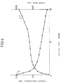
- Fig. 4 shows the change of the contact resistance thus evaluated.
- FIG. 4 shows the results thus obtained. As obvious from Fig. 4, it is understood that there are constant relations between the contact resistance values and the flank wear values. Thus, wear of an insert can be evaluated by measuring contact resistance according to the present invention.
Landscapes
- Engineering & Computer Science (AREA)
- Human Computer Interaction (AREA)
- Manufacturing & Machinery (AREA)
- Physics & Mathematics (AREA)
- General Physics & Mathematics (AREA)
- Automation & Control Theory (AREA)
- Mechanical Engineering (AREA)
- Measurement Of Length, Angles, Or The Like Using Electric Or Magnetic Means (AREA)
- Machine Tool Sensing Apparatuses (AREA)
- Cutting Tools, Boring Holders, And Turrets (AREA)
Claims (4)
- Methode zur Ermittlung des Verschleisses von Schneidwerkzeugen zum Schneiden eines Werkstücks (1) aus einem gemessenen Kontaktwiderstand, wobei die Methode die Schritte umfaßt:
Einspeisen eines Stromes zwischen dem Schneidewerkzeug (2) und dem Werkstück (1), um eine Potentialdifferenz, die über dem Schneidewerkzeug und dem Werkstück liegt, und den Wert des Kontaktwiderstands zu ermitteln, wobei die Methode gekennzeichnet ist durch
Unterbrechen des Stromes, der zwischen dem Schneidewerkzeug und dem Werkstück fließt, um eine thermoelektromotorische Kraft zu ermitteln, die durch den Kontakt zwischen dem Schneidewerkzeug und dem Werkstück erzeugt wird;
Abziehen der thermoelektromotorischen Kraft von der Potentialdifferenz und Teilen des Ergebnisses durch den Stromwert, um dadurch den Kontaktwiderstand zwischen dem Schneidewerkzeug und dem Werkstück zu messen; und
Ermitteln des Verschleisses des Schneidewerkzeugs aus dem gemessenen Kontaktwiderstand. - Methode nach Anspruch 1, worin das Schneidewerkzeug (2) aus beschichtetem Sinterkarbid gebildet wird.
- Methode nach Anspruch 1, worin das Schneidewerkzeug (2) aus Sinterkarbid gebildet wird.
- Methode nach Anspruch 1, worin der Kontaktwiderstand durch eine Vierpol-Methode gemessen wird.
Applications Claiming Priority (2)
| Application Number | Priority Date | Filing Date | Title |
|---|---|---|---|
| JP63259850A JPH02106254A (ja) | 1988-10-14 | 1988-10-14 | 工具摩耗検出法 |
| JP259850/88 | 1988-10-14 |
Publications (3)
| Publication Number | Publication Date |
|---|---|
| EP0363902A2 EP0363902A2 (de) | 1990-04-18 |
| EP0363902A3 EP0363902A3 (de) | 1993-09-22 |
| EP0363902B1 true EP0363902B1 (de) | 1995-07-19 |
Family
ID=17339845
Family Applications (1)
| Application Number | Title | Priority Date | Filing Date |
|---|---|---|---|
| EP89118807A Expired - Lifetime EP0363902B1 (de) | 1988-10-14 | 1989-10-10 | Methode zur Ermittlung des Verschleisses von Schneidwerkzeugen |
Country Status (5)
| Country | Link |
|---|---|
| US (1) | US5030920A (de) |
| EP (1) | EP0363902B1 (de) |
| JP (1) | JPH02106254A (de) |
| KR (1) | KR930004184B1 (de) |
| DE (1) | DE68923521T2 (de) |
Families Citing this family (14)
| Publication number | Priority date | Publication date | Assignee | Title |
|---|---|---|---|---|
| JPH06262492A (ja) * | 1993-03-17 | 1994-09-20 | Fanuc Ltd | 外乱負荷推定による工具の寿命管理方法 |
| KR100201020B1 (ko) * | 1994-03-11 | 1999-06-15 | 모리시타 요이찌 | 컴퓨터시뮬레이션부착 nc제어미세가공방법과 이 방법에 사용하는 장치 |
| FR2733064B1 (fr) * | 1995-04-14 | 1997-05-30 | Dufour Francois Et Fils | Procede et dispositif de controle d'usinage sur machine-outil |
| AU3310297A (en) * | 1996-06-26 | 1998-01-14 | Gleason Works, The | Detecting tool wear by thermal monitoring of workpiece |
| FR2775519B1 (fr) * | 1998-02-27 | 2000-05-12 | Lorraine Laminage | Dispositif et procede de mesure en continu de l'usure d'une paroi de recipient metallurgique |
| DE19813033A1 (de) * | 1998-03-25 | 1999-09-30 | Gottzmann Andreas | Bruch und Verschleißüberwachung |
| US6758640B2 (en) * | 2000-10-11 | 2004-07-06 | Fuji Seiko Limited | Method and apparatus for controlling movement of cutting blade and workpiece |
| EP2476511B1 (de) * | 2011-01-14 | 2013-03-27 | ARTIS GmbH | Vorrichtung und Verfahren zum Überwachen einer Werkzeugmaschine |
| DE102014204833A1 (de) * | 2014-03-14 | 2015-09-17 | Werner Kluft | Vorrichtung, Werkzeugmaschine und Verfahren zum Messen und Überwachen von Werkzeugen bzw. Werkstücken |
| US10184775B2 (en) * | 2016-04-20 | 2019-01-22 | Shawn Lause | Standard tool diameter gage |
| US10935359B2 (en) | 2016-04-20 | 2021-03-02 | Shawn Thomas Lause | Standard tool diameter gage |
| CN113030183B (zh) * | 2021-03-01 | 2023-04-07 | 深圳市金洲精工科技股份有限公司 | 钻头的涂层脱落检测方法 |
| DE102021110855A1 (de) | 2021-04-28 | 2022-11-03 | Herrenknecht Aktiengesellschaft | Schneidrad für eine Tunnelvortriebsmaschine |
| CN114800039B (zh) * | 2022-04-08 | 2023-03-14 | 山东大学 | 一种在线监测薄壁件铣削刀具状态的特征强化方法及系统 |
Family Cites Families (10)
| Publication number | Priority date | Publication date | Assignee | Title |
|---|---|---|---|---|
| GB1259272A (de) * | 1967-11-27 | 1972-01-05 | ||
| US4207567A (en) * | 1977-11-17 | 1980-06-10 | The Valeron Corporation | Broken, chipped and worn tool detector |
| JPS5820743B2 (ja) * | 1978-06-28 | 1983-04-25 | トヨタ自動車株式会社 | 工作機械の工具異常検知方法 |
| JPS5536457A (en) * | 1978-09-08 | 1980-03-14 | Ajinomoto Co Inc | Amino acid infusion |
| JPS57138558A (en) * | 1981-02-16 | 1982-08-26 | Mitsubishi Heavy Ind Ltd | Detecting device of contact of tool with work, as well defect in tool |
| JPS5832825Y2 (ja) * | 1981-08-20 | 1983-07-21 | 株式会社 阪村機械製作所 | ダイス交換装置 |
| US4694686A (en) * | 1984-06-18 | 1987-09-22 | Borg-Warner Corporation | Cutting tool wear monitor |
| SE452911B (sv) * | 1984-07-06 | 1987-12-21 | Birger Alvelid | Forfarande for framstellning av tillstandsgivare for mekaniska komponenter, jemte dylika mekaniska komponenter |
| JPS62218053A (ja) * | 1986-03-18 | 1987-09-25 | Ishikawajima Harima Heavy Ind Co Ltd | 工具折損検出装置 |
| US4831365A (en) * | 1988-02-05 | 1989-05-16 | General Electric Company | Cutting tool wear detection apparatus and method |
-
1988
- 1988-10-14 JP JP63259850A patent/JPH02106254A/ja active Pending
-
1989
- 1989-10-10 DE DE68923521T patent/DE68923521T2/de not_active Expired - Fee Related
- 1989-10-10 EP EP89118807A patent/EP0363902B1/de not_active Expired - Lifetime
- 1989-10-13 US US07/421,612 patent/US5030920A/en not_active Expired - Fee Related
- 1989-10-14 KR KR1019890014728A patent/KR930004184B1/ko not_active Expired - Fee Related
Also Published As
| Publication number | Publication date |
|---|---|
| KR930004184B1 (ko) | 1993-05-21 |
| DE68923521D1 (de) | 1995-08-24 |
| US5030920A (en) | 1991-07-09 |
| JPH02106254A (ja) | 1990-04-18 |
| EP0363902A3 (de) | 1993-09-22 |
| DE68923521T2 (de) | 1996-02-08 |
| EP0363902A2 (de) | 1990-04-18 |
| KR900006075A (ko) | 1990-05-07 |
Similar Documents
| Publication | Publication Date | Title |
|---|---|---|
| EP0363902B1 (de) | Methode zur Ermittlung des Verschleisses von Schneidwerkzeugen | |
| EP0349528B1 (de) | Verfahren und gerät zur messung von grössen bezüglich elektrisch leitender materialien | |
| Lan et al. | In-process tool fracture detection | |
| Stephenson | Assessment of steady-state metal cutting temperature models based on simultaneous infrared and thermocouple data | |
| El-Wardany et al. | Cutting temperature of ceramic tools in high speed machining of difficult-to-cut materials | |
| EP0146605B1 (de) | Verfahren und Vorrichtung zum Messen des spezifischen Widerstandes von Metallen | |
| Mannan et al. | Monitoring and adaptive control of cutting process by means of motor power and current measurements | |
| JPH03503862A (ja) | 状態インジケータを備えた切削工具 | |
| Kinoshita et al. | Study on wire-EDM: inprocess measurement of mechanical behaviour of electrode-wire | |
| Emel et al. | Acoustic emission and force sensor fusion for monitoring the cutting process | |
| TAKEYAMA et al. | Sensors of tool life for optimization of machining | |
| EP0468451A2 (de) | Verfahren und Vorrichtung zur Positionierung von zwei Werkstücken durch Abschätzung der Potentialdifferenz zwischen ihnen | |
| US5059905A (en) | Indication of cutting tool wear by monitoring eddy currents induced in a metallic workpiece | |
| US3728621A (en) | Apparatus for measuring the wear of cutting edges of cutting tools | |
| US4854161A (en) | Method for diagnosing cutting tool dullness | |
| CA1156311A (en) | Sorting device for tubular goods | |
| Tay et al. | Calculation of temperature distributions in machining using a hybrid finite-element-boundary-element method | |
| Li et al. | A new sensor for real-time milling tool condition monitoring | |
| Uehara et al. | Prognostication of the chipping of cutting tools | |
| US3084986A (en) | Method for machine control | |
| SU1045015A1 (ru) | Способ измерени силы резани | |
| JPS61182574A (ja) | 工具折損予知装置 | |
| SU1143514A1 (ru) | Способ измерени тангенциальной составл ющей силы резани при многоразовом точении | |
| JPH1015737A (ja) | 放電加工用加工液の良否を検査する方法及び装置 | |
| Cook et al. | Criticism of Radioactive Tool-Life Testing |
Legal Events
| Date | Code | Title | Description |
|---|---|---|---|
| PUAI | Public reference made under article 153(3) epc to a published international application that has entered the european phase |
Free format text: ORIGINAL CODE: 0009012 |
|
| AK | Designated contracting states |
Kind code of ref document: A2 Designated state(s): DE FR GB SE |
|
| 17P | Request for examination filed |
Effective date: 19901219 |
|
| PUAL | Search report despatched |
Free format text: ORIGINAL CODE: 0009013 |
|
| AK | Designated contracting states |
Kind code of ref document: A3 Designated state(s): DE FR GB SE |
|
| 17Q | First examination report despatched |
Effective date: 19940426 |
|
| GRAA | (expected) grant |
Free format text: ORIGINAL CODE: 0009210 |
|
| AK | Designated contracting states |
Kind code of ref document: B1 Designated state(s): DE FR GB SE |
|
| REF | Corresponds to: |
Ref document number: 68923521 Country of ref document: DE Date of ref document: 19950824 |
|
| ET | Fr: translation filed | ||
| PLBE | No opposition filed within time limit |
Free format text: ORIGINAL CODE: 0009261 |
|
| STAA | Information on the status of an ep patent application or granted ep patent |
Free format text: STATUS: NO OPPOSITION FILED WITHIN TIME LIMIT |
|
| 26N | No opposition filed | ||
| PGFP | Annual fee paid to national office [announced via postgrant information from national office to epo] |
Ref country code: GB Payment date: 19971001 Year of fee payment: 9 |
|
| PG25 | Lapsed in a contracting state [announced via postgrant information from national office to epo] |
Ref country code: GB Free format text: LAPSE BECAUSE OF NON-PAYMENT OF DUE FEES Effective date: 19981010 |
|
| GBPC | Gb: european patent ceased through non-payment of renewal fee |
Effective date: 19981010 |
|
| PGFP | Annual fee paid to national office [announced via postgrant information from national office to epo] |
Ref country code: DE Payment date: 20001002 Year of fee payment: 12 |
|
| PGFP | Annual fee paid to national office [announced via postgrant information from national office to epo] |
Ref country code: SE Payment date: 20001009 Year of fee payment: 12 |
|
| PGFP | Annual fee paid to national office [announced via postgrant information from national office to epo] |
Ref country code: FR Payment date: 20001010 Year of fee payment: 12 |
|
| PG25 | Lapsed in a contracting state [announced via postgrant information from national office to epo] |
Ref country code: SE Free format text: LAPSE BECAUSE OF NON-PAYMENT OF DUE FEES Effective date: 20011011 |
|
| EUG | Se: european patent has lapsed |
Ref document number: 89118807.0 |
|
| PG25 | Lapsed in a contracting state [announced via postgrant information from national office to epo] |
Ref country code: FR Free format text: LAPSE BECAUSE OF NON-PAYMENT OF DUE FEES Effective date: 20020628 |
|
| PG25 | Lapsed in a contracting state [announced via postgrant information from national office to epo] |
Ref country code: DE Free format text: LAPSE BECAUSE OF NON-PAYMENT OF DUE FEES Effective date: 20020702 |
|
| REG | Reference to a national code |
Ref country code: FR Ref legal event code: ST |