EP0363948A1 - Buse pour machines de moulage par injection - Google Patents
Buse pour machines de moulage par injection Download PDFInfo
- Publication number
- EP0363948A1 EP0363948A1 EP89118957A EP89118957A EP0363948A1 EP 0363948 A1 EP0363948 A1 EP 0363948A1 EP 89118957 A EP89118957 A EP 89118957A EP 89118957 A EP89118957 A EP 89118957A EP 0363948 A1 EP0363948 A1 EP 0363948A1
- Authority
- EP
- European Patent Office
- Prior art keywords
- nozzle
- mold
- bore
- injection molding
- hollow needle
- Prior art date
- Legal status (The legal status is an assumption and is not a legal conclusion. Google has not performed a legal analysis and makes no representation as to the accuracy of the status listed.)
- Granted
Links
- 238000001746 injection moulding Methods 0.000 title claims abstract description 20
- 239000004033 plastic Substances 0.000 claims abstract description 42
- 238000002347 injection Methods 0.000 claims abstract description 7
- 239000007924 injection Substances 0.000 claims abstract description 7
- 239000007788 liquid Substances 0.000 claims abstract description 7
- 238000009413 insulation Methods 0.000 claims description 4
- 230000000295 complement effect Effects 0.000 claims description 3
- 238000010438 heat treatment Methods 0.000 claims description 3
- 238000000465 moulding Methods 0.000 claims description 2
- 239000002991 molded plastic Substances 0.000 abstract description 7
- 239000000463 material Substances 0.000 abstract description 4
- 229920000642 polymer Polymers 0.000 abstract 2
- 230000015572 biosynthetic process Effects 0.000 description 2
- 238000000034 method Methods 0.000 description 2
- 238000010276 construction Methods 0.000 description 1
- 230000007547 defect Effects 0.000 description 1
- 238000011010 flushing procedure Methods 0.000 description 1
- 238000007789 sealing Methods 0.000 description 1
- 238000007711 solidification Methods 0.000 description 1
- 230000008023 solidification Effects 0.000 description 1
- QERYCTSHXKAMIS-UHFFFAOYSA-M thiophene-2-carboxylate Chemical compound [O-]C(=O)C1=CC=CS1 QERYCTSHXKAMIS-UHFFFAOYSA-M 0.000 description 1
- 238000012795 verification Methods 0.000 description 1
Images

Classifications
-
- B—PERFORMING OPERATIONS; TRANSPORTING
- B29—WORKING OF PLASTICS; WORKING OF SUBSTANCES IN A PLASTIC STATE IN GENERAL
- B29C—SHAPING OR JOINING OF PLASTICS; SHAPING OF MATERIAL IN A PLASTIC STATE, NOT OTHERWISE PROVIDED FOR; AFTER-TREATMENT OF THE SHAPED PRODUCTS, e.g. REPAIRING
- B29C45/00—Injection moulding, i.e. forcing the required volume of moulding material through a nozzle into a closed mould; Apparatus therefor
- B29C45/17—Component parts, details or accessories; Auxiliary operations
- B29C45/20—Injection nozzles
-
- B—PERFORMING OPERATIONS; TRANSPORTING
- B29—WORKING OF PLASTICS; WORKING OF SUBSTANCES IN A PLASTIC STATE IN GENERAL
- B29C—SHAPING OR JOINING OF PLASTICS; SHAPING OF MATERIAL IN A PLASTIC STATE, NOT OTHERWISE PROVIDED FOR; AFTER-TREATMENT OF THE SHAPED PRODUCTS, e.g. REPAIRING
- B29C45/00—Injection moulding, i.e. forcing the required volume of moulding material through a nozzle into a closed mould; Apparatus therefor
- B29C45/17—Component parts, details or accessories; Auxiliary operations
- B29C45/1703—Introducing an auxiliary fluid into the mould
- B29C45/1704—Introducing an auxiliary fluid into the mould the fluid being introduced into the interior of the injected material which is still in a molten state, e.g. for producing hollow articles
-
- B—PERFORMING OPERATIONS; TRANSPORTING
- B29—WORKING OF PLASTICS; WORKING OF SUBSTANCES IN A PLASTIC STATE IN GENERAL
- B29C—SHAPING OR JOINING OF PLASTICS; SHAPING OF MATERIAL IN A PLASTIC STATE, NOT OTHERWISE PROVIDED FOR; AFTER-TREATMENT OF THE SHAPED PRODUCTS, e.g. REPAIRING
- B29C44/00—Shaping by internal pressure generated in the material, e.g. swelling or foaming ; Producing porous or cellular expanded plastics articles
- B29C44/02—Shaping by internal pressure generated in the material, e.g. swelling or foaming ; Producing porous or cellular expanded plastics articles for articles of definite length, i.e. discrete articles
- B29C44/04—Shaping by internal pressure generated in the material, e.g. swelling or foaming ; Producing porous or cellular expanded plastics articles for articles of definite length, i.e. discrete articles consisting of at least two parts of chemically or physically different materials, e.g. having different densities
- B29C44/0492—Devices for feeding the different materials
-
- B—PERFORMING OPERATIONS; TRANSPORTING
- B29—WORKING OF PLASTICS; WORKING OF SUBSTANCES IN A PLASTIC STATE IN GENERAL
- B29C—SHAPING OR JOINING OF PLASTICS; SHAPING OF MATERIAL IN A PLASTIC STATE, NOT OTHERWISE PROVIDED FOR; AFTER-TREATMENT OF THE SHAPED PRODUCTS, e.g. REPAIRING
- B29C44/00—Shaping by internal pressure generated in the material, e.g. swelling or foaming ; Producing porous or cellular expanded plastics articles
- B29C44/02—Shaping by internal pressure generated in the material, e.g. swelling or foaming ; Producing porous or cellular expanded plastics articles for articles of definite length, i.e. discrete articles
- B29C44/10—Applying counter-pressure during expanding
- B29C44/105—Applying counter-pressure during expanding the counterpressure being exerted by a fluid
-
- B—PERFORMING OPERATIONS; TRANSPORTING
- B29—WORKING OF PLASTICS; WORKING OF SUBSTANCES IN A PLASTIC STATE IN GENERAL
- B29C—SHAPING OR JOINING OF PLASTICS; SHAPING OF MATERIAL IN A PLASTIC STATE, NOT OTHERWISE PROVIDED FOR; AFTER-TREATMENT OF THE SHAPED PRODUCTS, e.g. REPAIRING
- B29C44/00—Shaping by internal pressure generated in the material, e.g. swelling or foaming ; Producing porous or cellular expanded plastics articles
- B29C44/34—Auxiliary operations
- B29C44/58—Moulds
- B29C44/581—Closure devices for pour holes
-
- B—PERFORMING OPERATIONS; TRANSPORTING
- B29—WORKING OF PLASTICS; WORKING OF SUBSTANCES IN A PLASTIC STATE IN GENERAL
- B29C—SHAPING OR JOINING OF PLASTICS; SHAPING OF MATERIAL IN A PLASTIC STATE, NOT OTHERWISE PROVIDED FOR; AFTER-TREATMENT OF THE SHAPED PRODUCTS, e.g. REPAIRING
- B29C45/00—Injection moulding, i.e. forcing the required volume of moulding material through a nozzle into a closed mould; Apparatus therefor
- B29C45/16—Making multilayered or multicoloured articles
-
- B—PERFORMING OPERATIONS; TRANSPORTING
- B29—WORKING OF PLASTICS; WORKING OF SUBSTANCES IN A PLASTIC STATE IN GENERAL
- B29C—SHAPING OR JOINING OF PLASTICS; SHAPING OF MATERIAL IN A PLASTIC STATE, NOT OTHERWISE PROVIDED FOR; AFTER-TREATMENT OF THE SHAPED PRODUCTS, e.g. REPAIRING
- B29C45/00—Injection moulding, i.e. forcing the required volume of moulding material through a nozzle into a closed mould; Apparatus therefor
- B29C45/17—Component parts, details or accessories; Auxiliary operations
- B29C45/1703—Introducing an auxiliary fluid into the mould
- B29C45/1734—Nozzles therefor
-
- B—PERFORMING OPERATIONS; TRANSPORTING
- B29—WORKING OF PLASTICS; WORKING OF SUBSTANCES IN A PLASTIC STATE IN GENERAL
- B29C—SHAPING OR JOINING OF PLASTICS; SHAPING OF MATERIAL IN A PLASTIC STATE, NOT OTHERWISE PROVIDED FOR; AFTER-TREATMENT OF THE SHAPED PRODUCTS, e.g. REPAIRING
- B29C45/00—Injection moulding, i.e. forcing the required volume of moulding material through a nozzle into a closed mould; Apparatus therefor
- B29C45/17—Component parts, details or accessories; Auxiliary operations
- B29C45/46—Means for plasticising or homogenising the moulding material or forcing it into the mould
- B29C45/56—Means for plasticising or homogenising the moulding material or forcing it into the mould using mould parts movable during or after injection, e.g. injection-compression moulding
-
- B—PERFORMING OPERATIONS; TRANSPORTING
- B29—WORKING OF PLASTICS; WORKING OF SUBSTANCES IN A PLASTIC STATE IN GENERAL
- B29C—SHAPING OR JOINING OF PLASTICS; SHAPING OF MATERIAL IN A PLASTIC STATE, NOT OTHERWISE PROVIDED FOR; AFTER-TREATMENT OF THE SHAPED PRODUCTS, e.g. REPAIRING
- B29C67/00—Shaping techniques not covered by groups B29C39/00 - B29C65/00, B29C70/00 or B29C73/00
- B29C67/004—Closing perforations or small holes, e.g. using additional moulding material
-
- B—PERFORMING OPERATIONS; TRANSPORTING
- B29—WORKING OF PLASTICS; WORKING OF SUBSTANCES IN A PLASTIC STATE IN GENERAL
- B29C—SHAPING OR JOINING OF PLASTICS; SHAPING OF MATERIAL IN A PLASTIC STATE, NOT OTHERWISE PROVIDED FOR; AFTER-TREATMENT OF THE SHAPED PRODUCTS, e.g. REPAIRING
- B29C45/00—Injection moulding, i.e. forcing the required volume of moulding material through a nozzle into a closed mould; Apparatus therefor
- B29C45/17—Component parts, details or accessories; Auxiliary operations
- B29C45/1703—Introducing an auxiliary fluid into the mould
- B29C45/1704—Introducing an auxiliary fluid into the mould the fluid being introduced into the interior of the injected material which is still in a molten state, e.g. for producing hollow articles
- B29C2045/1718—Introducing an auxiliary fluid into the mould the fluid being introduced into the interior of the injected material which is still in a molten state, e.g. for producing hollow articles sealing or closing the fluid injection opening
Definitions
- the invention relates to a nozzle for injection molding machines according to the features of the preamble of main claim 1.
- a generic nozzle is already known from DE-OS 21 06 546.
- This nozzle carries only a hollow needle of constant length, firmly connected with it, which, when the mold is closed, always extends to the plastic core of the plastic injected first by means of another nozzle, but always opens when the mold is opened after the plastic injected first is solidified or at least - if the second medium is a further plastic component - leaves a clear disturbance of the surface in the molded plastic article.
- two-component nozzles have a much more complicated design than nozzles for a single component of an injection molding system that processes multiple components simultaneously, so that it is in many cases easier and cheaper to maintain, an injection molding system for the simultaneous processing of multiple components with multiple nozzles for one component each to be injected instead of being equipped with a single multi-component nozzle.
- the object of the present invention is therefore to provide a nozzle for injection molding machines with which a second medium can be introduced into the interior of a first plastic melt that has already been partially or completely injected into an injection mold, this nozzle on the one hand with a minimal structural design the seamless closing of the passage opening for the second medium by the first plastic melt and, on the other hand - at least when the second medium is a pressurized gas or a pressurized liquid - allows the interior of the plastic article to be depressurized within the closed mold without an external opening of the plastic article.
- the invention solves this problem with the aid of the features of the characterizing part of main claim 1.
- the nozzle according to the invention has two concentrically arranged hollow needles in its mold-side outlet channel, both with respect to the wall of the outlet channel of the nozzle or a bore possibly flushing it up to the mold surface, and also with one another in the axial direction which can be displaced in a fitting manner , wherein the inner hollow needle is closed at its mold-side end, but instead has one or more exit openings in its side wall above its mold-side end, and preferably can be extended into the mold cavity to such an extent that the exit openings are approximately at the middle height between the two mold surfaces in the Area of the exit channel or the hole reach their working point.
- the inner hollow needle can be used as a feed for the second medium, which can first be inserted sufficiently deep into a first plastic melt already in the mold cavity in order to then inject the second medium into the first plastic melt essentially parallel and symmetrically to the mold surfaces , while the outer hollow needle remains retracted so far that there is between the inner hollow needle and the wall of the exit channel of the nozzle or a bore in the mold, which continues flush to the mold surface, can store a sufficient amount of material of the first plastic melt for the subsequent formation of a sealing plug.
- the extended inner hollow needle can advantageously also be formed after the formation of an inner bladder of the second medium in the first plastic melt and the beginning of the hardening of the outer layer from the first plastic melt use for pressure equalization between the interior of the plastic body and the atmosphere.
- the end faces of the two hollow needles while simultaneously extending both hollow needles to the level of the closest mold surface, complement these almost without any problems.
- This allows the inner hollow needle to be retracted after the pressure between the interior of the plastic body and the atmosphere has been equalized so that the end faces of both hollow needles are at the same level, in order to then extend both hollow needles together to the nearest mold surface, the one between the inner hollow needle and the wall of the outlet channel of the nozzle or a supply of material of the first plastic melt stored in the mold and continuing it in alignment is pressed as a seamless plug into the outer wall of the plastic body.
- the wall of its mold-side outlet channel or a bore in the mold that continues flush to the mold surface is provided with special heat insulation and / or a heating device.
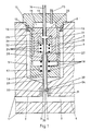
- FIG. 1 shows a section of a mold 1 of an injection molding machine with a mold cavity 3 enclosed between two mold surfaces 2 and 4, which can be partially or completely filled with a plasticized plastic melt by means of a nozzle, not shown, of a known type.
- a bore 5 is let into a part of the molding tool 1, which tapers at its end on the mold side and then merges into a further bore 6 with a smaller diameter.
- a nozzle 7 is inserted, which is locked in the bore 5 by means of a non-positive connection 8, for example a screw thread.
- the nozzle 7 initially consists of a two-part nozzle housing, which is composed of a nozzle body 9 and a nozzle chamber closure 10.
- the nozzle chamber closure 10 is formed in the case shown as a screw, for example as such with a hexagon screw head, with a central recess 11, the inner diameter of this central recess 11 being smaller than that of a piston 12 which can be displaced in the axial direction in the nozzle body 9, so that part of the screw end surface facing away from the head serves as a stop for the piston 12.
- the nozzle chamber closure 10 has a central bore 13 in the case shown, which acts as a sliding seal for an axially displaceable supply line 14 is used to supply the nozzle 7 with the second medium to be injected into the mold cavity 3, and also contains a non-positively connected supply line 15 for a pneumatic or hydraulic pressure medium to be inserted into or removed from the central recess 11.
- the nozzle chamber closure 10 is locked on the one hand by means of the non-positive connection 8 in the bore 5 and on the other hand carries the nozzle body 9 by means of further non-positive connections 16.
- the nozzle body 9 essentially represents a hollow cylinder in which a piston 12 is axially displaceable. At the end on the mold side, this nozzle body 9 initially has a constriction 17 of its inner diameter, which forms a further stop for the piston 12 and the seat for a spring 18, which is only indicated here, while a further constriction of its inner diameter then represents the mold-side outlet channel 19 of the nozzle 7 .
- the piston 12 is also a mechanically opening and non-positively locking hollow cylinder, the parting line and possible embodiment of a non-positive connection is not shown explicitly in the present illustration for the sake of simplicity.
- a further axially displaceable piston 20 with a central bore 21, in which an inner hollow needle 23 leading out of the piston 20 in the direction of the mold cavity 3 is locked by means of a non-positive connection 22, and one the Piston 20 in the idle state against the spring 24 holding the shape-facing end of the cavity.
- the inner cavity of the piston 12 is connected at its shape-facing end to the feed line 14 of the second medium, which by means of a non-positive connection 25 in a central bore 26 in the piston 12 is anchored.
- the piston 12 also has at its mold-side end a further central bore 27, in which a further Rich 28 by means of a non-positive connection device on the mold cavity 3 leading out of the piston 12 - outer - hollow needle 29 is locked.
- Bore 27 and outer hollow needle 29 are dimensioned such that the inner hollow needle 23 is at least in the outer hollow needle 29 fit to fit, without the movement of the bore 27 being impeded.
- the outlet channel 19 of the nozzle 7 and the bore 6 are designed so that the outer hollow needle 29 can slide in both bores in a fitting manner.
- Both hollow needles 23 and 29 are matched in length to one another in such a way that they end in the idle state on the mold side at the same level, in the case shown within the bore 6, with a different nozzle arrangement possibly also within the outlet channel 19, but in such a way that in front of the End faces 30 and 31 of both hollow needles 23 and 29 outside of the actual mold cavity 3 can store a part of the plastic melt injected first.
- the end faces 30 and 31 are designed such that they add largely to the level of the closest mold surface 2 when moving together. This means in particular that the end face 30 of the inner hollow needle 23 is closed.
- the inner hollow needle 23 has one or more outlet openings (32) for the second medium immediately behind its end face 30 Allow a plastic melt injected first to enter largely parallel to the mold surfaces 2 and 4.
- the mouth area of the bore 6 is provided with a heating device 33 and / or a special heat insulation 34, with the aid of which the part of the plastic melt which was initially injected and which was initially stored in the bore 6 is kept at a lower viscosity than the rest until a plug is formed the plastic melt injected first.
- Corresponding devices can optionally also be installed in the mouth area of the outlet channel 19 of the nozzle 7.
- FIG. 2 shows the position of the mold-side ends of the hollow needles 23 and 29 in various stages of an injection molding process, the starting position of which is already shown in FIG. 1.
- a first plastic melt 35 is first injected into the mold cavity 3 from a nozzle of a known type (not shown), part of this first plastic melt in the mouth region of the bore 6 outside of the hole 6 according to FIG. 2a with the ends of the hollow needles 23 and 29 unchanged actual mold cavity 3 is stored.
- the supply line 14 in FIG. 1 is pressurized by means of a known type of control, not shown, whereby the piston 20 is moved against the force of the spring 24 so far in the direction of the mold cavity 3 that the outlet openings 32 of the inner hollow needle 23 approximately open come to a stop halfway between the mold surfaces 2 and 4 and the second medium 36 transported through the feed line 14 and the hollow needle 23 according to FIG. 2b is pressed into the plastic melt 35 injected essentially parallel to the mold surfaces 2 and 4.
- the supply line 14 is connected to the atmosphere or a known type of storage container, which is under atmospheric pressure, by means of the control, not shown, of known type, whereby the second medium 36 in the injection molded plastic article is relieved of pressure and at the same time the piston 20 and move the inner hollow needle 23 back to its starting position according to FIG. 2c.
- the plastic melt first injected now forms a hollow body filled with the second medium 36 under approximately atmospheric pressure, one part the plastic melt is still stored in the mouth area of the bore 6.
- This part of the plastic melt 35 is now pressed down to the level of the mold surface 2, according to FIG. 2d, by applying a pneumatic or hydraulic pressure medium to the central recess 11 in the nozzle chamber closure 10 via the feed line 15, according to FIG. 1, via a supply line 15 so that the piston 12, ie at the same time also the piston 20 or the hollow needles 23 and 29, against the force of the spring 18, is moved so far in the direction of the nearest mold surface 2 that the end faces 30 and 31 of the hollow needles 23 and 29 complement the mold surface 2 essentially without interference.
- the feed line 15 is relieved of pressure by the known control system, not shown, so that the piston 12 and with it the piston 20 and the hollow needles 23 and 29 return to their starting position according to FIG. 1.
- the injection molding process is finished and can be repeated after the mold is closed again.
Landscapes
- Engineering & Computer Science (AREA)
- Mechanical Engineering (AREA)
- Manufacturing & Machinery (AREA)
- Injection Moulding Of Plastics Or The Like (AREA)
- Moulds For Moulding Plastics Or The Like (AREA)
- Blow-Moulding Or Thermoforming Of Plastics Or The Like (AREA)
Priority Applications (1)
| Application Number | Priority Date | Filing Date | Title |
|---|---|---|---|
| AT89118957T ATE74821T1 (de) | 1988-10-13 | 1989-10-12 | Duese fuer spritzgiessmaschinen. |
Applications Claiming Priority (2)
| Application Number | Priority Date | Filing Date | Title |
|---|---|---|---|
| DE3834917A DE3834917A1 (de) | 1988-10-13 | 1988-10-13 | Duese fuer spritzgiessmaschinen |
| DE3834917 | 1988-10-13 |
Publications (2)
| Publication Number | Publication Date |
|---|---|
| EP0363948A1 true EP0363948A1 (fr) | 1990-04-18 |
| EP0363948B1 EP0363948B1 (fr) | 1992-04-15 |
Family
ID=6365059
Family Applications (1)
| Application Number | Title | Priority Date | Filing Date |
|---|---|---|---|
| EP89118957A Expired - Lifetime EP0363948B1 (fr) | 1988-10-13 | 1989-10-12 | Buse pour machines de moulage par injection |
Country Status (6)
| Country | Link |
|---|---|
| US (1) | US4990083A (fr) |
| EP (1) | EP0363948B1 (fr) |
| KR (1) | KR920004044B1 (fr) |
| AT (1) | ATE74821T1 (fr) |
| DE (2) | DE3834917A1 (fr) |
| ES (1) | ES2032644T3 (fr) |
Cited By (13)
| Publication number | Priority date | Publication date | Assignee | Title |
|---|---|---|---|---|
| EP0467201A3 (en) * | 1990-07-18 | 1992-05-06 | Toyoda Gosei Co., Ltd. | Mold for hollow injection molding |
| FR2682063A1 (fr) * | 1991-10-04 | 1993-04-09 | Peguform Werke Gmbh | Systeme de filieres pour le moulage par injection d'elements de grande surface en matiere plastique avec des cavites fermees. |
| EP0577840A4 (fr) * | 1991-12-27 | 1993-11-11 | Asahi Chemical Ind | Procede de moulage par soufflage et dispositif d'injection et de decharge de fluide pressurise relatif. |
| DE4240017A1 (de) * | 1992-11-27 | 1994-06-01 | Wolf Woco & Co Franz J | Verfahren zur Herstellung von zumindest zweiseitig offenen hohlen Formteilen |
| EP0639441A1 (fr) * | 1993-08-17 | 1995-02-22 | MASCHINENFABRIK HENNECKE GmbH | Procédé et dispositif de remplissage des cuves de mousse polyuréthane sans CFC |
| FR2716135A1 (fr) * | 1994-02-14 | 1995-08-18 | Braun Pebra Gmbh | Valve d'injection de gaz intégré et machine de moulage équipée d'une telle valve. |
| EP0668140A1 (fr) * | 1994-02-15 | 1995-08-23 | M + C SCHIFFER GmbH | Procédé et dispositif pour fabriquer des brosses à dents |
| EP0714745A1 (fr) * | 1994-12-02 | 1996-06-05 | Cheil Industries Inc. | Dispositif et procédé pour mouler par injection un objet en résine thermoplastique |
| EP0679491A3 (fr) * | 1994-04-28 | 1996-08-07 | Krauss Maffei Ag | Machine à mouler par injection pour fabriquer des récipients à paroi creuse. |
| US7184009B2 (en) | 2002-06-21 | 2007-02-27 | Nokia Corporation | Display circuit with optical sensor |
| WO2014013304A1 (fr) * | 2012-07-17 | 2014-01-23 | Illinois Tool Works Inc. | Procédé et dispositif pour produire une pièce de matière plastique, en particulier une pièce de matière plastique pour automobile, au moyen d'un procédé de moulage par injection |
| EP2614942B1 (fr) * | 2012-01-11 | 2019-04-10 | Jsp Corporation | Procédé de production d'article moulé en mousse recouvert de peau et appareil de production de celui-ci |
| EP3885100A1 (fr) * | 2020-03-25 | 2021-09-29 | Braunform GmbH | Outil de moulage par injection de pièces en matière plastique |
Families Citing this family (30)
| Publication number | Priority date | Publication date | Assignee | Title |
|---|---|---|---|---|
| DE3936289C2 (de) * | 1989-11-01 | 1996-01-25 | Battenfeld Gmbh | Vorrichtung zum Spritzgießen von Hohlräume enthaltenden Gegenständen aus Kunststoff |
| US5137680A (en) | 1990-07-16 | 1992-08-11 | Milad Limited Partnership | Method of injection molding utilizing pressurized fluid source within a chamber in a mold |
| DE4024549C2 (de) * | 1990-08-02 | 1994-12-08 | Helphos Gmbh | Verfahren zur Herstellung von Spritzgußteilen |
| US5127814A (en) * | 1990-11-26 | 1992-07-07 | Nitrojection Corporation | Apparatus for producing a fluid-assisted injection molded product |
| US5200127A (en) * | 1990-12-17 | 1993-04-06 | Automotive Plastic Technologies, Inc. | Method and apparatus for gas assisted injection molding |
| US5282730A (en) * | 1991-06-12 | 1994-02-01 | Automotive Plastic Technologies | Retractable gas injection pin for an injection mold |
| US5304058A (en) * | 1991-06-12 | 1994-04-19 | Automotive Plastic Technologies | Injection nozzle |
| US5306134A (en) * | 1991-06-12 | 1994-04-26 | Automotive Plastic Technologies | Fluid forcing nozzle |
| US5256047A (en) * | 1991-12-03 | 1993-10-26 | Nitrojection Corporation | Gas assisted injection molding apparatus utilizing sleeve and pin arrangement |
| US5273417A (en) * | 1992-03-12 | 1993-12-28 | Automotive Plastic Technologies, Inc. | Nozzle for gas-assisted injection molding |
| DE4222510C1 (de) * | 1992-07-09 | 1993-12-09 | Edmund Ullisperger | Nadelverschlußdüse für Kunststoff-Spritzmassen |
| MY116615A (en) * | 1992-07-13 | 2004-03-31 | Aron Kasei Kk | Process for producing expanded plastics with skin and molding apparatus therefor |
| DE4237062C1 (de) * | 1992-11-03 | 1994-02-17 | Kloeckner Ferromatik Desma | Gasinjektionsdüse für Spritzgießmaschinen |
| US5302337A (en) * | 1993-06-11 | 1994-04-12 | Cascade Engineering, Inc. | Method for making a coated gas-assisted injection molded article |
| US5464342A (en) * | 1993-09-24 | 1995-11-07 | Nitrojection Corporation | Pin in barrel injection molding nozzle using short pin |
| FR2731377B1 (fr) * | 1995-03-06 | 1997-05-09 | Happich Mecanique | Injecteur de gaz pour le moulage de pieces creuses en matiere plastique |
| TW349914B (en) * | 1995-10-19 | 1999-01-11 | Chrysler Corp | Car body part |
| US5698242A (en) * | 1995-12-20 | 1997-12-16 | General Instrument Corporation Of Delaware | Apparatus for the injection molding of semiconductor elements |
| CN1139472C (zh) * | 1996-03-18 | 2004-02-25 | 株式会社理光 | 一种细长轴构件 |
| DE19713874B4 (de) * | 1997-04-04 | 2008-08-07 | Gardena Manufacturing Gmbh | Vorrichtung zur Einleitung von Gas in ein Formwerkzeug |
| US6000925A (en) * | 1997-12-22 | 1999-12-14 | Alexander V. Daniels | Gas assisted injection molding system |
| DE19815681A1 (de) * | 1998-04-08 | 1999-10-14 | Thimm Verpackung Gmbh & Co | Spritzgießverfahren |
| KR100296969B1 (ko) * | 1999-02-23 | 2001-09-22 | 허남욱 | 카드형 성형물 제조용 합성수지 사출 노즐 |
| DE10158663C1 (de) * | 2001-11-30 | 2003-05-08 | Siemens Ag | Verfahren zur Erzeugung einer Leitung aus Kunststoff mit einem Abzweig und Werkzeug zur Fertigung einer einen Abzweig aufweisenden Leitung |
| DE20209643U1 (de) * | 2002-06-21 | 2003-08-14 | ERGOPLAST Kunststoff GmbH, 09573 Leubsdorf | Vorrichtung zum Verschließen von Gasinjektionsöffnungen in Hohlprofilen aus Kunststoffen |
| US6739858B2 (en) * | 2002-08-29 | 2004-05-25 | Graham Packaging Company, L.P. | Insulated apparatus for injecting and removing compressed air from a cooled mold cavity |
| KR101606349B1 (ko) | 2014-07-07 | 2016-03-30 | 김상태 | 수목 성장 보호장치 |
| CN104162952B (zh) * | 2014-08-14 | 2017-04-19 | 漳州立达信光电子科技有限公司 | Led灯具散热壳体及其注射成型设备 |
| US10179430B2 (en) * | 2016-02-15 | 2019-01-15 | Ge Aviation Systems Llc | Hybrid part manufacturing system and method |
| DE102021123797A1 (de) | 2021-09-15 | 2023-03-16 | Bayerische Motoren Werke Aktiengesellschaft | Spritzgießverfahren zum Herstellen eines Medium-leitenden Formteils und Spritzgussformteil |
Citations (1)
| Publication number | Priority date | Publication date | Assignee | Title |
|---|---|---|---|---|
| EP0250080A2 (fr) * | 1986-05-19 | 1987-12-23 | Ladney, Michael | Procédé de moulage par injection |
Family Cites Families (8)
| Publication number | Priority date | Publication date | Assignee | Title |
|---|---|---|---|---|
| DE2106546A1 (de) * | 1971-02-11 | 1972-08-17 | Mohrbach E | Verfahren und Vorrichtung zum Spritz gießen von Gegenstanden aus Kunststoff |
| DE2501314A1 (de) * | 1975-01-15 | 1976-07-22 | Roehm Gmbh | Spritzgiessen hohler formteile aus thermoplastischen kunststoffen, insbesondere fuer den bausektor |
| GB1489291A (en) * | 1975-06-06 | 1977-10-19 | Weathershields Ltd | Open roof assemblies for vehicles |
| JPS59383B2 (ja) * | 1977-01-05 | 1984-01-06 | 旭化成株式会社 | 型物の成形法 |
| US4474717A (en) * | 1982-05-24 | 1984-10-02 | Lang Fastener Corporation | Method of making a twin-wall internally corrugated plastic structural part with a smooth non-cellular skin |
| GB2139548B (en) * | 1983-05-11 | 1986-11-19 | James Watson Hendry | Injection moulding |
| GB8706204D0 (en) * | 1987-03-16 | 1987-04-23 | Peerless Cinpres Ltd | Injection moulding apparatus |
| US4917594A (en) * | 1989-02-28 | 1990-04-17 | Mold-Masters Limited | Injection molding system with gas flow through valve gate |
-
1988
- 1988-10-13 DE DE3834917A patent/DE3834917A1/de active Granted
-
1989
- 1989-10-12 EP EP89118957A patent/EP0363948B1/fr not_active Expired - Lifetime
- 1989-10-12 AT AT89118957T patent/ATE74821T1/de not_active IP Right Cessation
- 1989-10-12 ES ES198989118957T patent/ES2032644T3/es not_active Expired - Lifetime
- 1989-10-12 DE DE8989118957T patent/DE58901171D1/de not_active Expired - Fee Related
- 1989-10-13 KR KR1019890014670A patent/KR920004044B1/ko not_active Expired
- 1989-10-13 US US07/421,116 patent/US4990083A/en not_active Expired - Fee Related
Patent Citations (1)
| Publication number | Priority date | Publication date | Assignee | Title |
|---|---|---|---|---|
| EP0250080A2 (fr) * | 1986-05-19 | 1987-12-23 | Ladney, Michael | Procédé de moulage par injection |
Cited By (20)
| Publication number | Priority date | Publication date | Assignee | Title |
|---|---|---|---|---|
| EP0467201A3 (en) * | 1990-07-18 | 1992-05-06 | Toyoda Gosei Co., Ltd. | Mold for hollow injection molding |
| US5198177A (en) * | 1990-07-18 | 1993-03-30 | Toyoda Gosei Co., Ltd. | Method of making a hollow molded product |
| US5295801A (en) * | 1990-07-18 | 1994-03-22 | Toyoda Gosei Co., Ltd. | Mold for hollow injection molding |
| FR2682063A1 (fr) * | 1991-10-04 | 1993-04-09 | Peguform Werke Gmbh | Systeme de filieres pour le moulage par injection d'elements de grande surface en matiere plastique avec des cavites fermees. |
| EP0577840A4 (fr) * | 1991-12-27 | 1993-11-11 | Asahi Chemical Ind | Procede de moulage par soufflage et dispositif d'injection et de decharge de fluide pressurise relatif. |
| US5409659A (en) * | 1991-12-27 | 1995-04-25 | Asahi Kasei Kogyo Kabushiki Kaisha | Hollow injection-molding method and pressurized fluid introducing and discharging apparatus therefor |
| DE4240017A1 (de) * | 1992-11-27 | 1994-06-01 | Wolf Woco & Co Franz J | Verfahren zur Herstellung von zumindest zweiseitig offenen hohlen Formteilen |
| DE4240017C2 (de) * | 1992-11-27 | 2001-03-15 | Wolf Woco & Co Franz J | Verfahren zur Herstellung von zumindest zweiseitig offenen hohlen Formteilen |
| EP0639441A1 (fr) * | 1993-08-17 | 1995-02-22 | MASCHINENFABRIK HENNECKE GmbH | Procédé et dispositif de remplissage des cuves de mousse polyuréthane sans CFC |
| FR2716135A1 (fr) * | 1994-02-14 | 1995-08-18 | Braun Pebra Gmbh | Valve d'injection de gaz intégré et machine de moulage équipée d'une telle valve. |
| EP0668140A1 (fr) * | 1994-02-15 | 1995-08-23 | M + C SCHIFFER GmbH | Procédé et dispositif pour fabriquer des brosses à dents |
| EP0679491A3 (fr) * | 1994-04-28 | 1996-08-07 | Krauss Maffei Ag | Machine à mouler par injection pour fabriquer des récipients à paroi creuse. |
| US5584470A (en) * | 1994-04-28 | 1996-12-17 | Krauss-Maffei Aktiengesellschaft | Method and apparatus for injection molding a hollow-wall container |
| EP0714745A1 (fr) * | 1994-12-02 | 1996-06-05 | Cheil Industries Inc. | Dispositif et procédé pour mouler par injection un objet en résine thermoplastique |
| US7184009B2 (en) | 2002-06-21 | 2007-02-27 | Nokia Corporation | Display circuit with optical sensor |
| EP2614942B1 (fr) * | 2012-01-11 | 2019-04-10 | Jsp Corporation | Procédé de production d'article moulé en mousse recouvert de peau et appareil de production de celui-ci |
| WO2014013304A1 (fr) * | 2012-07-17 | 2014-01-23 | Illinois Tool Works Inc. | Procédé et dispositif pour produire une pièce de matière plastique, en particulier une pièce de matière plastique pour automobile, au moyen d'un procédé de moulage par injection |
| US9944003B2 (en) | 2012-07-17 | 2018-04-17 | Illinois Tool Works Inc. | Method and device for producing a plastic part, especially a plastic part for an automobile, by an injection molding method |
| DE102012014013B4 (de) | 2012-07-17 | 2022-02-24 | Illinois Tool Works Inc. | Verfahren und Vorrichtung zur Herstellung eines Kunststoffteils, insbesondere eines Kunststoffteils für ein Automobil, in einem Spritzgussverfahren |
| EP3885100A1 (fr) * | 2020-03-25 | 2021-09-29 | Braunform GmbH | Outil de moulage par injection de pièces en matière plastique |
Also Published As
| Publication number | Publication date |
|---|---|
| US4990083A (en) | 1991-02-05 |
| ES2032644T3 (es) | 1993-02-16 |
| KR900006094A (ko) | 1990-05-07 |
| DE3834917A1 (de) | 1990-04-19 |
| EP0363948B1 (fr) | 1992-04-15 |
| DE3834917C2 (fr) | 1992-04-30 |
| DE58901171D1 (de) | 1992-05-21 |
| KR920004044B1 (ko) | 1992-05-23 |
| ATE74821T1 (de) | 1992-05-15 |
Similar Documents
| Publication | Publication Date | Title |
|---|---|---|
| EP0363948B1 (fr) | Buse pour machines de moulage par injection | |
| EP0393315B1 (fr) | Procédé pour mouler par injection des pièces en matière plastique remplies de liquide et appareil pour la réalisation du procédé | |
| DE3936289C2 (de) | Vorrichtung zum Spritzgießen von Hohlräume enthaltenden Gegenständen aus Kunststoff | |
| DE69115265T2 (de) | Verfahren und vorrichtung zum spritzgiessen von kunststoffgegenständen mit hilfe von gas. | |
| DE69104289T2 (de) | Form zum hohlen Spritzgiessen. | |
| DE2342794B2 (de) | Verfahren und Vorrichtung zum diskontinuierlichen Herstellen von Mehrschicht-Formteilen aus thermoplastischem Kunststoff | |
| DE3245571A1 (de) | Nadelverschluss-duese fuer spritzgiessformen | |
| DE3113294A1 (de) | "verfahren zur herstellung einer keramischen investmentgiessform" | |
| DE2027514A1 (de) | Schneckenspritzeinheit für Kunststoffe | |
| DE29809855U1 (de) | Nadelverschlußdüse | |
| DE69605784T2 (de) | Verfahren und system zum spritzgiessen unter verwendung eines überschussraums mit veränderlichem volumen und dadurch hergestellter gegenstand | |
| EP1712341B1 (fr) | Buse d'injection avec deux orifices de sortie | |
| DE2623308C3 (de) | Vorrichtung zum diskontinuierlichen Herstellen von Formteilen aus thermoplastischem Kunststoff | |
| DE2259818B2 (de) | SpritzgieBvorrichtung zum Herstellen eines Formkörpers mit einem Kern aus geschäumtem und einer Außenhaut aus ungeschäumten thermoplastischem Kunststoff | |
| DE19947984A1 (de) | Spritzgiessmaschine | |
| DE2342789C2 (de) | Vorrichtung zur diskontinuierlichen Herstellung von Mehrschicht-Formkörpern | |
| EP1599328A1 (fr) | Procede de production d'articles moules par injection et buse a obturation a aiguille pour moule a injection | |
| DE19703316B4 (de) | Verfahren und Vorrichtung zur Herstellung einer Düsenkartusche | |
| DE10039864C5 (de) | Spritzgußdüse | |
| EP0139841B1 (fr) | Procédé et dispositif pour fabriquer un corps creux en matériel thermoplastique par procédé de soufflage | |
| DE19713874B4 (de) | Vorrichtung zur Einleitung von Gas in ein Formwerkzeug | |
| DE3305931A1 (de) | Vorrichtung zum diskontinuierlichen herstellen von mehrschicht-formkoerpern aus kunststoff | |
| DE102011105765B4 (de) | Verfahren zum Spritzgießen von Kunststoff-Formteilen aus thermoplastischem Kunststoff | |
| DE19617484C1 (de) | Spritzgußvorrichtung und Spritzgußverfahren zur Herstellung von Hohlkörpern | |
| DE19515741C2 (de) | Verfahren und Spritzgießvorrichtung zum Herstellen eines wenigstens bereichsweise hohlen Kunststoffkörpers |
Legal Events
| Date | Code | Title | Description |
|---|---|---|---|
| PUAI | Public reference made under article 153(3) epc to a published international application that has entered the european phase |
Free format text: ORIGINAL CODE: 0009012 |
|
| 17P | Request for examination filed |
Effective date: 19891012 |
|
| AK | Designated contracting states |
Kind code of ref document: A1 Designated state(s): AT BE CH DE ES FR GB IT LI NL SE |
|
| 17Q | First examination report despatched |
Effective date: 19910923 |
|
| ITF | It: translation for a ep patent filed | ||
| GRAA | (expected) grant |
Free format text: ORIGINAL CODE: 0009210 |
|
| AK | Designated contracting states |
Kind code of ref document: B1 Designated state(s): AT BE CH DE ES FR GB IT LI NL SE |
|
| REF | Corresponds to: |
Ref document number: 74821 Country of ref document: AT Date of ref document: 19920515 Kind code of ref document: T |
|
| REF | Corresponds to: |
Ref document number: 58901171 Country of ref document: DE Date of ref document: 19920521 |
|
| GBT | Gb: translation of ep patent filed (gb section 77(6)(a)/1977) | ||
| ET | Fr: translation filed | ||
| PGFP | Annual fee paid to national office [announced via postgrant information from national office to epo] |
Ref country code: SE Payment date: 19920811 Year of fee payment: 4 |
|
| PGFP | Annual fee paid to national office [announced via postgrant information from national office to epo] |
Ref country code: FR Payment date: 19920814 Year of fee payment: 4 |
|
| PGFP | Annual fee paid to national office [announced via postgrant information from national office to epo] |
Ref country code: DE Payment date: 19920929 Year of fee payment: 4 |
|
| PGFP | Annual fee paid to national office [announced via postgrant information from national office to epo] |
Ref country code: BE Payment date: 19921002 Year of fee payment: 4 |
|
| PGFP | Annual fee paid to national office [announced via postgrant information from national office to epo] |
Ref country code: ES Payment date: 19921026 Year of fee payment: 4 |
|
| PGFP | Annual fee paid to national office [announced via postgrant information from national office to epo] |
Ref country code: AT Payment date: 19921028 Year of fee payment: 4 |
|
| PGFP | Annual fee paid to national office [announced via postgrant information from national office to epo] |
Ref country code: NL Payment date: 19921031 Year of fee payment: 4 |
|
| PGFP | Annual fee paid to national office [announced via postgrant information from national office to epo] |
Ref country code: CH Payment date: 19930129 Year of fee payment: 4 |
|
| REG | Reference to a national code |
Ref country code: ES Ref legal event code: FG2A Ref document number: 2032644 Country of ref document: ES Kind code of ref document: T3 |
|
| PLBE | No opposition filed within time limit |
Free format text: ORIGINAL CODE: 0009261 |
|
| STAA | Information on the status of an ep patent application or granted ep patent |
Free format text: STATUS: NO OPPOSITION FILED WITHIN TIME LIMIT |
|
| 26N | No opposition filed | ||
| PG25 | Lapsed in a contracting state [announced via postgrant information from national office to epo] |
Ref country code: GB Effective date: 19931012 Ref country code: AT Effective date: 19931012 |
|
| PG25 | Lapsed in a contracting state [announced via postgrant information from national office to epo] |
Ref country code: SE Effective date: 19931013 Ref country code: ES Free format text: LAPSE BECAUSE OF NON-PAYMENT OF DUE FEES Effective date: 19931013 |
|
| PG25 | Lapsed in a contracting state [announced via postgrant information from national office to epo] |
Ref country code: LI Effective date: 19931031 Ref country code: CH Effective date: 19931031 Ref country code: BE Effective date: 19931031 |
|
| BERE | Be: lapsed |
Owner name: KLOCKNER FERROMATIK DESMA G.M.B.H. Effective date: 19931031 |
|
| PG25 | Lapsed in a contracting state [announced via postgrant information from national office to epo] |
Ref country code: NL Effective date: 19940501 |
|
| GBPC | Gb: european patent ceased through non-payment of renewal fee |
Effective date: 19931012 |
|
| NLV4 | Nl: lapsed or anulled due to non-payment of the annual fee | ||
| PG25 | Lapsed in a contracting state [announced via postgrant information from national office to epo] |
Ref country code: FR Effective date: 19940630 |
|
| REG | Reference to a national code |
Ref country code: CH Ref legal event code: PL |
|
| PG25 | Lapsed in a contracting state [announced via postgrant information from national office to epo] |
Ref country code: DE Effective date: 19940701 |
|
| REG | Reference to a national code |
Ref country code: FR Ref legal event code: ST |
|
| EUG | Se: european patent has lapsed |
Ref document number: 89118957.3 Effective date: 19940510 |
|
| REG | Reference to a national code |
Ref country code: ES Ref legal event code: FD2A Effective date: 19990503 |
|
| PG25 | Lapsed in a contracting state [announced via postgrant information from national office to epo] |
Ref country code: IT Free format text: LAPSE BECAUSE OF NON-PAYMENT OF DUE FEES;WARNING: LAPSES OF ITALIAN PATENTS WITH EFFECTIVE DATE BEFORE 2007 MAY HAVE OCCURRED AT ANY TIME BEFORE 2007. THE CORRECT EFFECTIVE DATE MAY BE DIFFERENT FROM THE ONE RECORDED. Effective date: 20051012 |