EP0363955A2 - Vorrichtung zum Spannen sowie zum Drehen von rohrförmigen Werkstücken in einer Werkzeugmaschine - Google Patents
Vorrichtung zum Spannen sowie zum Drehen von rohrförmigen Werkstücken in einer Werkzeugmaschine Download PDFInfo
- Publication number
- EP0363955A2 EP0363955A2 EP89118978A EP89118978A EP0363955A2 EP 0363955 A2 EP0363955 A2 EP 0363955A2 EP 89118978 A EP89118978 A EP 89118978A EP 89118978 A EP89118978 A EP 89118978A EP 0363955 A2 EP0363955 A2 EP 0363955A2
- Authority
- EP
- European Patent Office
- Prior art keywords
- sleeve
- clamping
- jaws
- operatively connected
- chuck
- Prior art date
- Legal status (The legal status is an assumption and is not a legal conclusion. Google has not performed a legal analysis and makes no representation as to the accuracy of the status listed.)
- Granted
Links
Images

Classifications
-
- B—PERFORMING OPERATIONS; TRANSPORTING
- B23—MACHINE TOOLS; METAL-WORKING NOT OTHERWISE PROVIDED FOR
- B23B—TURNING; BORING
- B23B31/00—Chucks; Expansion mandrels; Adaptations thereof for remote control
- B23B31/02—Chucks
- B23B31/10—Chucks characterised by the retaining or gripping devices or their immediate operating means
- B23B31/12—Chucks with simultaneously-acting jaws, whether or not also individually adjustable
- B23B31/16—Chucks with simultaneously-acting jaws, whether or not also individually adjustable moving radially
- B23B31/16045—Jaws movement actuated by screws and nuts or oblique racks
- B23B31/16066—Jaws movement actuated by screws and nuts or oblique racks using fluid-pressure means to actuate the gripping means
- B23B31/1607—Jaws movement actuated by screws and nuts or oblique racks using fluid-pressure means to actuate the gripping means using mechanical transmission through the spindle
-
- B—PERFORMING OPERATIONS; TRANSPORTING
- B23—MACHINE TOOLS; METAL-WORKING NOT OTHERWISE PROVIDED FOR
- B23B—TURNING; BORING
- B23B31/00—Chucks; Expansion mandrels; Adaptations thereof for remote control
- B23B31/02—Chucks
- B23B31/10—Chucks characterised by the retaining or gripping devices or their immediate operating means
- B23B31/12—Chucks with simultaneously-acting jaws, whether or not also individually adjustable
- B23B31/16—Chucks with simultaneously-acting jaws, whether or not also individually adjustable moving radially
- B23B31/16045—Jaws movement actuated by screws and nuts or oblique racks
- B23B31/1605—Details of the jaws
- B23B31/16054—Form of the jaws
Definitions
- the above invention relates to a device for clamping and turning tubular workpieces in a machine tool, particularly in a machine for cutting tubes.
- a chuck which is firmly connected to a ring gear which meshes with a toothed wheel which is driven by a controllable motor, the chuck having a number of displaceable jaws which are mounted in inclined guides and are operatively connected to a drive sleeve are rotatably and displaceably mounted in the longitudinal direction that this drive sleeve is operatively connected to an axially operating displacement device which is designed in the manner of a piston-cylinder unit and the displacement device is assigned an adjustable stop in the axial direction.
- Both thin-walled and thick-walled tubes can be clamped perfectly because the stroke of the clamping jaws and thus the pressure force exerted on the pipe wall can be determined and precisely adjusted.
- the device allows a clamping of tubes with a small diameter as well as a clamping of tubes with a large diameter and it is possible to give the tube different speeds of rotation, according to prescribed cutting parameters.
- the clamping device consists of a known chuck 1, which with jaws 2, such as this. B. are common in lathes, is equipped.
- a cutting device 3 working with a laser beam is arranged in front of the clamping jaws 2 of the chuck 1.
- the clamping jaws 2 have the task of clamping the tube 4 in the chuck.
- the jaws 2 carry guide rods 5 inside the device 1
- Guide rods 5 have tapered ends 6 which allow the pipe piece 4 to be inserted easily and smoothly into the interior of the device 1.
- the device 1 and the jaws 2 are operatively connected to a ring gear 7.
- the ring gear 7 meshes with a gear 8, which is operatively connected to the shaft 10 of a drive motor 11 via a gear 9.
- the motor 11 advantageously consists of a direct current motor which can be controlled via an NC device of the machine tool. This allows the tensioning and rotating device 1 to be driven at a rotational speed which is advisable for carrying out various cutting processes.
- the ring gear 7 is operatively connected to a sleeve 12.
- the sleeve or sleeve 12 is supported by ball bearings 13 in the interior of the housing 14 of the clamping and rotating device 1.
- the sleeve 12 can perform a rotary movement.
- a further sleeve 15 is mounted in the rotatable sleeve 12, which sleeve can also carry out an axial movement in addition to a rotary movement, as indicated by the arrow f in FIG. 1.
- the front end of the sleeve 15 is connected to the jaws 2 in a manner known per se to the jaws 2. More precisely, the jaws 2 are operatively connected to inclined guide grooves 16 which are incorporated in the device 1. Thus, the jaws 2 can be Axialhubes of the sleeve 15 are driven in the radial direction.
- the axial movement of the sleeve 15 is carried out with the aid of a hydraulic piston-cylinder unit, which is identified overall by 17.
- the hydraulic cylinder 17 is arranged in the interior of the housing 14 of the device 1.
- the cylinder 17 is designed as a double-acting cylinder and has two openings 18 and 19 for feeding in or discharging the hydraulic fluid under pressure.
- the cylinder 17 receives a piston 20, which is advantageously designed as an annular piston.
- This ring piston 20 works with two thrust bearings 21 and 22 which are attached to the sleeve or sleeve 15 using stops and a union nut 23.
- the bearings 21 and 22 prevent the piston 20 from being rotated when the sleeve 15 rotates.
- the stroke of the piston 20 (opening movement of the jaws 2) is limited at the front of the device 1 by a fixed stop 24 which is provided in the interior of the cylinder 14.
- the sleeve or sleeve 15 has carried out its maximum stroke in the direction of the arrow (g). This stroke corresponds to the maximum opening stroke of the jaws 2.
- the backward stroke of the piston 20 and thus the backward stroke movement of the sleeve or sleeve 15 is determined by a ring nut 25.
- the nut 25 has on its outside a thread 26 which interacts with a threaded spindle 27 which has an endless thread.
- the threaded spindle 27 By operating the threaded spindle 27, e.g. B. via a handwheel, not shown, the threaded nut 25 is driven and moved via the thread 27 in the axial direction.
- the stroke of the piston 20 and thus of the sleeve 15 is precisely defined.
- the closing stroke of the jaws 2 can be determined with precision and the clamping force of the jaws 2 can be precisely metered.
- the clamping force of the jaws 2, which acts on the tube 4 is thus adjusted by the fact that the tube 4 is entrained during the cutting process by the laser device, but at the same time it prevents excessive forces being exerted by the clamping jaws 2 on the outer wall of the pipe are transmitted. This prevents damage or plastic deformation of the tube wall of tube 4 from occurring.
Landscapes
- Engineering & Computer Science (AREA)
- Mechanical Engineering (AREA)
- Gripping On Spindles (AREA)
Abstract
Description
- Die vorstehende Erfindung betrifft eine Vorrichtung zum Spannen und Drehen von rohrfoermigen Werkstuecken in einer Werkzeugmaschine, besonders in einer Maschine zum Trennen von Rohren.
- Zum Trennen von Rohren finden heute verschiedene Verfahren Anwendung.
- In letzter Zeit wurden zum Trennen von Rohren Lasereinrichtungen und aehnliche Verfahren vorgeschlagen. Bei diesen Vorrichtungen wird der Trennvorgang unter Verwendung eines Lichtstrahles vorgenommen. Durch den Laserstrahl werden Stuecke eines sich drehenden Rohres abgetrennt. Es ist notwendig in der Vorrichtung, rohrfoermige Werkstuecke mit unterschiedlichem Durchmesses mit der erforderlichen Sicherheit, aber auch Feinfuehligkeit zu spannen, um waehrend des Schneidvorganges des rohrfoermigen Werkstueckes, diesem eine gesteuerte Drehbewegung zu verleihen.
- Es ist Aufgabe der vorstehenden Erfindung, eine Vorrichtung vorzuschlagen, die ein feinfuehliges Spannen des Rohres ohne jegliche Verformung der Rohrwand zu ermoeglichen und zu erlauben, sowohl Rohre mit kleinem Druchmesser als auch Rohre mit grossem Durchmesser zu spannen und ein sicheres Einfuehren des Rohres in die Spannvorrichtung zu gestatten und gleichzeitig einen Drehantrieb zum Antreiben des Rohrstueckes mit der gewuenschten Geschwindigkeit zur Durchfuehrung des Schneidvorganges vorzuschlagen.
- Diese Aufgabe wird erfindungsgemaess mit einem Spannfutter erreicht, das mit einem Zahnkranz fest verbunden ist, der mit einem Zahnrad kaemmt, das ueber einen steuerbaren Motor angetrieben wird, wobei das Spannfutter eine Anzahl verschiebbar und in geneigten Fuehrungen gelagerte Backen aufweist, die mit einer Antriebsmuffe wirkverbunden sind, die drehbar sowie in Laengsrichtung verschiebbar gelagert ist, dass diese Antriebsmuffe mit einer in Axialrichtung arbeitenden Verschiebevorrichtung wirkverbunden ist, die nach Art einer Kolben-Zylindereinheit ausgebildet ist und der Verschiebevorrichtung ein in Axialrichtung einstellbarer Anschlag zugeordnet ist.
- Mit einer derartigen Vorrichtung wird ein Mittel zum sicheren Spannen von Rohrstuecken geschaffen. Es koennen sowohl duennwandige als auch dickwandige Rohre einwandfrei gespannt werden, da der Hub der Spannbacken und somit die auf die Rohrwandung ausgeuebte Druckkraft festgelegt und genau eingestellt werden kann. Die Vorrichtung erlaubt ein Spannen von Rohren mit kleinem Durchmesser als auch ein Spannen von Rohren mit grossem Durchmesser und es ist moeglich, dem Rohr unterschiedliche Drehgeschwindigkeiten, entsprechend vorgeschriebenen Schnittparametern, zu verleihen.
- Die Erfindung wird nun genauer beschrieben und anhand eines Ausfuehrungsbeispieles in den Zeichnungen dargestellt.
- Es zeigen:
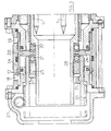
- Fig. 1 die erfindungsgemaesse Spann- und Drehvorrichtung im Schnitt;
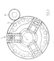
- Fig. 2 eine Vorderansicht der erfindungsgemaessen Spanneinrichtung; und
- Fig. 3 ein Detail in des rueckwaertigen Teiles der Spann- und Drehvorrichtung im Schnitt.
- Wie der Fig. 1 zu entnehmen ist, besteht die Spannvorrichtung aus einem an sich bekannten Spannfutter 1, das mit Spannbacken 2, wie diese z. B. bei Drehmaschinen ueblich sind, ausgeruestet ist.
- Vor den Spannbacken 2 des Futters 1 ist eine mit einem Laserstrahl arbeitende Schneidvorrichtung 3 angeordnet. Die Spannbacken 2 haben die Aufgabe, das Rohr 4 im Futter zu spannen. In vorteilhafter Weise tragen die Spannbacken 2 im Inneren der Vorrichtung 1 Fuehrungsstangen 5. Diese Fuehrungsstangen 5 weisen zugespitzte Enden 6 auf, die ein leichtgaengiges und einwandfreies Einfuehren des Rohrstueckes 4 in das Innere der Vorrichtung 1 erlauben.
- Die Vorrichtung 1 sowie die Spannbacken 2 stehen mit einem Zahnkranz 7 in Wirkverbindung. Der Zahnkranz 7 kaemmt mit einem Zahnrad 8, welches ueber ein Getriebe 9 mit der Welle 10 eines Antriebsmotores 11 wirkverbunden ist. Der Motor 11 besteht in vorteilhafter Weise aus einem Gleichstrommotor, der ueber eine NC-Einrichtung der Werkzeugmaschine steuerbar ist. Dies erlaubt es, die Spann- und Drehvorrichtung 1 mit einer Drehgeschwindigkeit anzutreiben, die zur Durchfuehrung verschiedener Schneidvorgaenge ratsam sind.
- Der Zahnkranz 7 ist mit einer Muffe 12 wirkverbunden. Die Muffe oder Huelse 12 ist ueber Kugellager 13 im Inneren des Gehaeuses 14 der Spann- und Drehvorrichtung 1 gelagert. Somit kann die Muffe 12 eine Drehbewegung durchfuehren.
- In der drehbaren Muffe 12 ist eine weitere Huelse 15 gelagert, die neben einer Drehbewegung auch eine Axialbewegung durchfuehren kann, wie dies in Fig. 1 durch den Pfeil f angedeutet ist.
- Das vordere Ende der Huelse 15 ist mit den Backen 2 in an sich bekannter Weise mit den Backen 2 verbunden. Genauer gesagt stehen die Backen 2 mit geneigten Fuehrungsnuten 16, die in die Vorrichtung 1 eingearbeitet sind, in Wirkverbindung. Somit koennen die Backen 2 waehrend des Axialhubes der Huelse 15 in Radialrichtung angetrieben werden.
- Bei Bewegung der Huelse 15 in Richtung des Pfeiles (g) wird ein Oeffnen der Spannbacken 2 bewirkt; bei Bewegung der Huelse 15 in entgegengesetzter Richtung erfolgt eine Schliessbewegung der Backen 2. Dieses Antriebssystem fuer die Backen 2 zum Spannen des Rohres 4 bedarf keiner genaueren Beschreibung, da die Antriebsverbindung zwischen Spannbacken und Huelse aus dem Stand der Technik bekannt ist.
- Die Axialbewegung der Huelse 15 wird unter Zuhilfenahme einer hydraulischen Kolben-Zylindereinheit, die gesamthaft mit 17 gekennzeichnet ist, durchgefuehrt. Der Hydraulikzylinder 17 ist im Inneren des Gehaeuses 14 der Vorrichtung 1 angeordnet. Der Zylinder 17 ist als doppeltwirkender Zylinder ausgebildet und weist zwei Oeffnungen 18 und 19 fuer die Einspeisung bzw. die Abfuhr der unter Druck stehenden Hydraulikfluessigkeit auf. Der Zylinder 17 nimmt einen Kolben 20 auf, der in vorteilhafter Weise als Ringkolben ausgebildet ist. Dieser Ringkolben 20 arbeitet mit zwei Axiallagern 21 und 22 zusammen, die auf der Huelse oder Muffe 15 unter Verwendung von Anschlaegen und einer Ueberwurfmutter 23 befestigt sind. Die Lager 21 und 22 verhindern, dass der Kolben 20 verdreht wird, wenn durch die Huelse 15 eine Drehbewegung durchgefuehrt wird.
- Der Hub des Kolbens 20 (Oeffnungsbewegung der Backen 2) wird an der Vorderseite der Vorrichtung 1 durch einen festen Anschlag 24 begrenzt, der im Inneren des Zylinders 14 vorgesehen ist. Wenn der Kolben 20 mit dem Anschlag 24 in Wirkverbindung tritt, hat die Muffe oder Huelse 15 ihren maximalen Hub in Richtung des Pfeiles (g) durchgefuehrt. Dieser Hub entspricht dem maximalen Oeffnungshub der Spannbacken 2.
- Wird ueber ein bekanntes Elektroventil ueber die Oeffnung 18 die rueckwaertige Kammer des Zylinders 14 entleert und eine unter Druck stehende Hydraulikfluessigkeit ueber die Oeffnung 19 der vorderen Kammer des Zylinders 14 zugefuehrt, so wird der Kolben 20 nach rueckwaerts verfahren und zieht die Huelse 15 in entgegengesetzter Richtung zu der durch den Pfeil (g) angegebenen Richtung. Somit wird ueber die bekannte Einrichtung, bestehend aus geneigten Fuehrungen 16 und den dazugehoerigen Gleitzapfen, eine Schliessbewegung der Backen 2 und somit ein Spannen des Rohrstueckes 4 bewirkt. Um zu vermeiden, dass Rohre, besonders Rohre mit duenner Wand, durch die Spannbacken 2 verformt werden, ist es wichtig, eine Vorrichtung vorzusehen, die eine Begrenzung der von den Backen 2 auf das Rohr 4 uebertragenen Kraft ermoeglicht.
- Erfindungsgemaess ist zu diesem Zweck vorgesehen, dass der Rueckwaertshub des Kolbens 20 und somit die Rueckwaerts bewegung der Muffe oder Huelse 15 durch eine Ringmutter 25 festgelegt wird. Die Mutter 25 weist an ihrer Aussenseite ein Gewinde 26 auf, das mit einer Gewindespindel 27, die ein Endlosgewinde aufweist, zusammenwirkt. Durch Betaetigen der Gewindespindel 27, z. B. ueber ein nicht dargestelltes Handrad, wird auch die Gewindemutter 25 angetrieben und ueber das Gewinde 27 in Axialrichtung verschoben. Mit einer Lageeinstellung des vorderen Endes 28 der Gewindemutter 25, die als Anschlag fuer den Ringzylinder 20 dient, wird der Hub des Kolbens 20 und somit der Huelse 15 genau festgelegt. Auf diese Weise kann der Schliesshub der Backen 2 mit Praezision festgelegt werden und eine genaue Dosierung der Spannkraft der Backen 2 erfolgen. Die Spannkraft der Backen 2, die auf das Rohr 4 einwirkt, wird somit dadurch eingestellt, dass zwar eine Mitnahme der Rohres 4 waehrend des Schneidvorganges durch die Lasereinrichtung erfolgt, es wird aber gleichzeitig vermieden, dass zu hohe Kraefte ueber die Spannbacken 2 auf die Aussenwand des Rohres uebertragen werden. Dadurch wird vermieden, dass eine Beschaedigung oder plastische Verformung der Rohrwand des Rohres 4 eintritt.
Claims (7)
Applications Claiming Priority (2)
| Application Number | Priority Date | Filing Date | Title |
|---|---|---|---|
| IT2201888U | 1988-10-14 | ||
| IT2201888U IT215389Z2 (it) | 1988-10-14 | 1988-10-14 | Dispositivo per il bloccaggio nonche' la rotazione di barre tubolari in una macchina utensile. |
Publications (3)
| Publication Number | Publication Date |
|---|---|
| EP0363955A2 true EP0363955A2 (de) | 1990-04-18 |
| EP0363955A3 EP0363955A3 (de) | 1991-04-03 |
| EP0363955B1 EP0363955B1 (de) | 1994-12-14 |
Family
ID=11190271
Family Applications (1)
| Application Number | Title | Priority Date | Filing Date |
|---|---|---|---|
| EP19890118978 Expired - Lifetime EP0363955B1 (de) | 1988-10-14 | 1989-10-12 | Vorrichtung zum Spannen sowie zum Drehen von rohrförmigen Werkstücken in einer Werkzeugmaschine |
Country Status (3)
| Country | Link |
|---|---|
| EP (1) | EP0363955B1 (de) |
| DE (1) | DE58908771D1 (de) |
| IT (1) | IT215389Z2 (de) |
Cited By (1)
| Publication number | Priority date | Publication date | Assignee | Title |
|---|---|---|---|---|
| CN113528770A (zh) * | 2021-07-22 | 2021-10-22 | 洛阳升华感应加热股份有限公司 | 一种大型套圈类零件用液压夹紧装置 |
Families Citing this family (1)
| Publication number | Priority date | Publication date | Assignee | Title |
|---|---|---|---|---|
| CN116408397B (zh) * | 2023-03-24 | 2025-11-21 | 浙江长兴和良智能装备有限公司 | 一种全自动数控旋压机及其加工方法 |
Family Cites Families (2)
| Publication number | Priority date | Publication date | Assignee | Title |
|---|---|---|---|---|
| DE2256190A1 (de) * | 1972-11-16 | 1974-05-22 | Gildemeister Werkzeugmasch | Spanneinrichtung fuer mehrspindeldrehautomaten |
| DE3218083C2 (de) * | 1982-05-13 | 1986-11-27 | Hubert Dipl.-Ing. 5920 Bad Berleburg Bald | Vorrichtung zum Erzeugen eines Stelldrehmoments, insbesondere zum Verstellen der Position der Backen eines Futters oder der von ihnen ausgeübten Spannkraft |
-
1988
- 1988-10-14 IT IT2201888U patent/IT215389Z2/it active
-
1989
- 1989-10-12 DE DE58908771T patent/DE58908771D1/de not_active Expired - Fee Related
- 1989-10-12 EP EP19890118978 patent/EP0363955B1/de not_active Expired - Lifetime
Cited By (1)
| Publication number | Priority date | Publication date | Assignee | Title |
|---|---|---|---|---|
| CN113528770A (zh) * | 2021-07-22 | 2021-10-22 | 洛阳升华感应加热股份有限公司 | 一种大型套圈类零件用液压夹紧装置 |
Also Published As
| Publication number | Publication date |
|---|---|
| IT215389Z2 (it) | 1990-09-11 |
| EP0363955A3 (de) | 1991-04-03 |
| DE58908771D1 (de) | 1995-01-26 |
| IT8822018V0 (it) | 1988-10-14 |
| EP0363955B1 (de) | 1994-12-14 |
Similar Documents
| Publication | Publication Date | Title |
|---|---|---|
| DE1752834C3 (de) | Antrieb für die Spindel einer Bohr- oder Fräsmaschine | |
| DE2331032A1 (de) | Zufuehrungsvorrichtung bei automatischen drehbaenken | |
| DE68902953T2 (de) | Bohrmaschine, insbesondere fuer programmierbare maschine. | |
| DE2238698C3 (de) | Vorrichtung zum Erodieren konischer Durchbrüche | |
| DE2651889C3 (de) | Einziehwerkzeug | |
| DE19503772C2 (de) | Maschine zum Schälen von Rohren und Stangen (Dreh-Schälmaschine) | |
| EP0363955A2 (de) | Vorrichtung zum Spannen sowie zum Drehen von rohrförmigen Werkstücken in einer Werkzeugmaschine | |
| EP2139631A1 (de) | Zentrierfutter zur zentrierung von materialstangen | |
| DE949702C (de) | Umlaufender Messerkopf | |
| DE4120349C1 (en) | Pipe cut=off mechanism with peripheral cutter wheels - whose support rotating in stationary housing, releasably fitted to retainer body | |
| DE1752732B2 (de) | Einrichtung zum oeffnen einer in einer werkzeugmaschinenspindel angeordneten werkzeug-spannzange | |
| EP0362698A2 (de) | Maschine zum automatischen Biegen von Rohren und ähnlichen Teilen | |
| EP0314936B1 (de) | Verfahren und Maschine für die plastische Verformung rohrförmiger Körper | |
| DE2334667A1 (de) | Honwerkzeug zum aussenhonen von werkstuecken | |
| DE870628C (de) | Selbsttaetiger Mitnehmer fuer Drehbaenke | |
| DE102022108639B3 (de) | Anschlagsvorrichtung für eine Drehmaschine | |
| EP1060832A1 (de) | Verfahren und Vorrichtung zum Halten von Werkstücken beim koaxialen Schleifen | |
| DE2313485B2 (de) | Spannfutter | |
| DE1477278A1 (de) | Vorschubeinrichtung fuer Automatendrehbaenke | |
| DE1552185C (de) | Maschine und Werkzeuge für das Rollen von konischen Gewindeteilen an Schrauben | |
| DE2559557C3 (de) | Stangenzuführvorrichtung für eine Drehmaschine | |
| DE477929C (de) | Gewindefraesmaschine mit drei gleichmaessig im Kreise verteilten und radial bewegbaren Rillenfraesern | |
| DE1752732C (de) | Einrichtung zum Offnen einer in einer Werkzeugmaschinenspindel angeordneten Werk stuck Spannzange | |
| DE917467C (de) | Selbsttaetige Drehbank zur Bearbeitung der Aussenflaeche eines becherfoermigen Werkstueckes | |
| DE1503075C (de) | Stiftschraubeneinschraubvornchtung |
Legal Events
| Date | Code | Title | Description |
|---|---|---|---|
| PUAI | Public reference made under article 153(3) epc to a published international application that has entered the european phase |
Free format text: ORIGINAL CODE: 0009012 |
|
| AK | Designated contracting states |
Kind code of ref document: A2 Designated state(s): BE CH DE ES FR GB IT LI NL |
|
| PUAL | Search report despatched |
Free format text: ORIGINAL CODE: 0009013 |
|
| AK | Designated contracting states |
Kind code of ref document: A3 Designated state(s): BE CH DE ES FR GB IT LI NL |
|
| RHK1 | Main classification (correction) |
Ipc: B23B 31/16 |
|
| 17P | Request for examination filed |
Effective date: 19910702 |
|
| 17Q | First examination report despatched |
Effective date: 19911217 |
|
| GRAA | (expected) grant |
Free format text: ORIGINAL CODE: 0009210 |
|
| AK | Designated contracting states |
Kind code of ref document: B1 Designated state(s): BE CH DE ES FR GB IT LI NL |
|
| PG25 | Lapsed in a contracting state [announced via postgrant information from national office to epo] |
Ref country code: IT Free format text: LAPSE BECAUSE OF FAILURE TO SUBMIT A TRANSLATION OF THE DESCRIPTION OR TO PAY THE FEE WITHIN THE PRESCRIBED TIME-LIMIT;WARNING: LAPSES OF ITALIAN PATENTS WITH EFFECTIVE DATE BEFORE 2007 MAY HAVE OCCURRED AT ANY TIME BEFORE 2007. THE CORRECT EFFECTIVE DATE MAY BE DIFFERENT FROM THE ONE RECORDED. Effective date: 19941214 Ref country code: NL Effective date: 19941214 Ref country code: BE Effective date: 19941214 Ref country code: ES Free format text: THE PATENT HAS BEEN ANNULLED BY A DECISION OF A NATIONAL AUTHORITY Effective date: 19941214 Ref country code: GB Effective date: 19941214 Ref country code: FR Effective date: 19941214 |
|
| REF | Corresponds to: |
Ref document number: 58908771 Country of ref document: DE Date of ref document: 19950126 |
|
| EN | Fr: translation not filed | ||
| NLV1 | Nl: lapsed or annulled due to failure to fulfill the requirements of art. 29p and 29m of the patents act | ||
| GBV | Gb: ep patent (uk) treated as always having been void in accordance with gb section 77(7)/1977 [no translation filed] |
Effective date: 19941214 |
|
| PLBE | No opposition filed within time limit |
Free format text: ORIGINAL CODE: 0009261 |
|
| STAA | Information on the status of an ep patent application or granted ep patent |
Free format text: STATUS: NO OPPOSITION FILED WITHIN TIME LIMIT |
|
| 26N | No opposition filed | ||
| REG | Reference to a national code |
Ref country code: CH Ref legal event code: NV Representative=s name: PATENTANWAELTE BREITER + WIEDMER AG Ref country code: CH Ref legal event code: PUE Owner name: ADIGE SALA S.P.A. Free format text: SALA S.P.A.#VIA PER BARCO, 11#LEVICO (IT) -TRANSFER TO- ADIGE SALA S.P.A.#VIA PER BARCO 11#38056 LEVICO (IT) |
|
| REG | Reference to a national code |
Ref country code: CH Ref legal event code: PFA Owner name: ADIGE SALA S.P.A. Free format text: ADIGE SALA S.P.A.#VIA PER BARCO 11#38056 LEVICO (IT) -TRANSFER TO- ADIGE SALA S.P.A.#VIA PER BARCO 11#38056 LEVICO (IT) |
|
| PGFP | Annual fee paid to national office [announced via postgrant information from national office to epo] |
Ref country code: DE Payment date: 20071030 Year of fee payment: 19 |
|
| PGFP | Annual fee paid to national office [announced via postgrant information from national office to epo] |
Ref country code: CH Payment date: 20071029 Year of fee payment: 19 |
|
| REG | Reference to a national code |
Ref country code: CH Ref legal event code: PL |
|
| PG25 | Lapsed in a contracting state [announced via postgrant information from national office to epo] |
Ref country code: DE Free format text: LAPSE BECAUSE OF NON-PAYMENT OF DUE FEES Effective date: 20090501 |
|
| PG25 | Lapsed in a contracting state [announced via postgrant information from national office to epo] |
Ref country code: LI Free format text: LAPSE BECAUSE OF NON-PAYMENT OF DUE FEES Effective date: 20081031 Ref country code: CH Free format text: LAPSE BECAUSE OF NON-PAYMENT OF DUE FEES Effective date: 20081031 |