EP0364041B1 - Système d'enregistrement et d'utilisation des repères - Google Patents
Système d'enregistrement et d'utilisation des repères Download PDFInfo
- Publication number
- EP0364041B1 EP0364041B1 EP89202536A EP89202536A EP0364041B1 EP 0364041 B1 EP0364041 B1 EP 0364041B1 EP 89202536 A EP89202536 A EP 89202536A EP 89202536 A EP89202536 A EP 89202536A EP 0364041 B1 EP0364041 B1 EP 0364041B1
- Authority
- EP
- European Patent Office
- Prior art keywords
- signal
- marking
- stage
- time
- signals
- Prior art date
- Legal status (The legal status is an assumption and is not a legal conclusion. Google has not performed a legal analysis and makes no representation as to the accuracy of the status listed.)
- Expired - Lifetime
Links
- 238000001514 detection method Methods 0.000 claims description 27
- 238000005259 measurement Methods 0.000 claims description 9
- 238000011156 evaluation Methods 0.000 description 25
- 239000003550 marker Substances 0.000 description 21
- 230000001960 triggered effect Effects 0.000 description 4
- 230000015572 biosynthetic process Effects 0.000 description 3
- 239000000203 mixture Substances 0.000 description 3
- 238000012986 modification Methods 0.000 description 3
- 230000004048 modification Effects 0.000 description 3
- 238000012545 processing Methods 0.000 description 3
- 238000012937 correction Methods 0.000 description 2
- 238000010586 diagram Methods 0.000 description 2
- 230000003287 optical effect Effects 0.000 description 2
- 230000017105 transposition Effects 0.000 description 2
- 238000004804 winding Methods 0.000 description 2
- 230000005540 biological transmission Effects 0.000 description 1
- 238000013461 design Methods 0.000 description 1
- 238000005265 energy consumption Methods 0.000 description 1
- 238000012854 evaluation process Methods 0.000 description 1
- 238000003780 insertion Methods 0.000 description 1
- 230000037431 insertion Effects 0.000 description 1
Images


Classifications
-
- G—PHYSICS
- G11—INFORMATION STORAGE
- G11B—INFORMATION STORAGE BASED ON RELATIVE MOVEMENT BETWEEN RECORD CARRIER AND TRANSDUCER
- G11B27/00—Editing; Indexing; Addressing; Timing or synchronising; Monitoring; Measuring tape travel
- G11B27/10—Indexing; Addressing; Timing or synchronising; Measuring tape travel
- G11B27/19—Indexing; Addressing; Timing or synchronising; Measuring tape travel by using information detectable on the record carrier
- G11B27/28—Indexing; Addressing; Timing or synchronising; Measuring tape travel by using information detectable on the record carrier by using information signals recorded by the same method as the main recording
- G11B27/30—Indexing; Addressing; Timing or synchronising; Measuring tape travel by using information detectable on the record carrier by using information signals recorded by the same method as the main recording on the same track as the main recording
- G11B27/3018—Indexing; Addressing; Timing or synchronising; Measuring tape travel by using information detectable on the record carrier by using information signals recorded by the same method as the main recording on the same track as the main recording used signal is a pilot signal outside the frequency band of the recorded main information signal
-
- G—PHYSICS
- G11—INFORMATION STORAGE
- G11B—INFORMATION STORAGE BASED ON RELATIVE MOVEMENT BETWEEN RECORD CARRIER AND TRANSDUCER
- G11B27/00—Editing; Indexing; Addressing; Timing or synchronising; Monitoring; Measuring tape travel
- G11B27/10—Indexing; Addressing; Timing or synchronising; Measuring tape travel
- G11B27/19—Indexing; Addressing; Timing or synchronising; Measuring tape travel by using information detectable on the record carrier
- G11B27/28—Indexing; Addressing; Timing or synchronising; Measuring tape travel by using information detectable on the record carrier by using information signals recorded by the same method as the main recording
- G11B27/30—Indexing; Addressing; Timing or synchronising; Measuring tape travel by using information detectable on the record carrier by using information signals recorded by the same method as the main recording on the same track as the main recording
- G11B27/3009—Indexing; Addressing; Timing or synchronising; Measuring tape travel by using information detectable on the record carrier by using information signals recorded by the same method as the main recording on the same track as the main recording used signal is a pilot signal inside the frequency band of the recorded main information signal
-
- G—PHYSICS
- G11—INFORMATION STORAGE
- G11B—INFORMATION STORAGE BASED ON RELATIVE MOVEMENT BETWEEN RECORD CARRIER AND TRANSDUCER
- G11B2220/00—Record carriers by type
- G11B2220/90—Tape-like record carriers
Definitions
- the invention relates to a system for recording and evaluating marking signals that can be stored on a recording medium and can be scanned from the same, distinguishable from one another, with a recording device for recording the marking signals to be stored and with an evaluation device for evaluating the scanned marking signals, the recording device generating a generator device of the marking signals to be stored and the evaluation device has a detector device for detecting the scanned marking signals and the generator device has a first generator stage for generating a first signal having a first frequency, a second generator stage for generating a second signal having a second frequency, the first and the second frequency are different, a first timing stage with which the occurrence period for the first signal can be determined, and a second timing stage with d it contains the occurrence period for the second signal, and, to generate a marking signal of a first type consisting only of the first signal, the first timing stage for the occurrence period of the first signal has a predetermined value T and at the same time the second timing stage for the occurrence period of the second signal defines the value zero and, in
- Such a system is used in a dictation system manufactured and sold by the applicant, known under the name mini-cassette dictation system, table-top dictation machines and portable pocket dictation machines, with which both the recording and the playback of dictations is possible, and evaluation devices, which are only suitable for playing dictations.
- marking signals of two different types can be stored on the recording medium designed as a magnetic tape, in order to be able to identify specific locations of dictations by recording the marking signals and to be able to find them again by evaluating the scanned marking signals .
- the end of a dictation is in each case with a marking signal of a first type, which consists of a first sinusoidal signal with a frequency of 40 Hz, which is generated, for example, during an occurrence period of 650 msec and is recorded on the magnetic tape at a predetermined normal speed of travel identifiable.
- a marking signal of a first type which consists of a first sinusoidal signal with a frequency of 40 Hz, which is generated, for example, during an occurrence period of 650 msec and is recorded on the magnetic tape at a predetermined normal speed of travel identifiable.
- a marker signal of a second type which consists of the first sinusoidal signal with a frequency of 40 Hz and a second sinusoidal signal with a frequency of 1500 Hz, which simultaneously generates during the same period of 650 msec and also at the normal speed of travel of the magnetic tape Dictation points to which the dictator has given or wants to give special instructions, correction instructions or the like, which must be taken into account by a typist when evaluating the dictation by a typist, can be identified.
- the marking signals of the first and second types differ from one another in that a marking signal of the first type consists only of one signal which has a predetermined frequency and a predetermined occurrence time period, and a marking signal of the second type consists of two Signals exist, of which one signal has the same frequency as the first marker signal and the other signal one has a different frequency and both have the same time span as the first marker signal.
- the evaluation of the marking signals of the first and second types scanned by the magnetic tape takes place in the known system at a higher moving speed of the magnetic tape than the recording of the marking signals, this moving speed being for example a factor 20 higher than the moving speed when recording the marking signals.
- This higher speed of movement when evaluating the scanned marking signals leads to a transposition of the frequencies of the signals that make up the marking signals by a factor of 20, so that when evaluating a marking signal of the first type, a first sinusoidal signal with a frequency of 40 Hz corresponding signal with a frequency of 800 Hz and when evaluating a marker signal of the second type a signal corresponding to the first sinusoidal signal with a frequency of 40 Hz with a frequency of 800 Hz and a second sinusoidal signal with a frequency of 1500 Hz corresponding signal is sampled at a frequency of 30 kHz from the magnetic tape.
- the evaluation device for the marking signals of the first and second types scanned by the magnetic tape in the known system has a detector device which has a first detector stage for detecting a signal with a frequency of 800 Hz and a second detector stage for detecting a signal with a frequency of 30 kHz, both of which emit an output signal when the corresponding signal occurs, which are fed to a logic stage following the two detector stages. If only the first detector stage emits such an output signal, the logic stage generates a detection signal corresponding to a marking signal of the first type. If both detector stages emit such an output signal, the logic stage generates a detection signal corresponding to a marking signal of the second type.
- These detection signals can be fed to an optical or acoustic display device. However, they can also be supplied to a switch-off device for switching off the drive device for the magnetic tape, wherein then the movement of the magnetic tape is interrupted by switching off the drive device for the magnetic tape when a marking signal is detected.
- the invention has therefore set itself the task of satisfying this need and designing a system of the type mentioned at the beginning in such a way that at least one marking signal of a third type can be generated and evaluated with the system according to the invention, although not the type of such a marking signal of the third type , but the presence of the same can also be determined with an evaluation device of the known existing system in order to ensure compatibility between the existing system and the system according to the invention with regard to the determination of the presence of marking signals.
- a time measuring stage for measuring the occurrence time span contains at least one corresponding signal which, depending on the measured time span, supplies different measured values of the logic stage for generating the detection signals corresponding to the marking signals scanned by the recording medium.
- the occurrence time period of at least one signal in a marking signal of the third type is defined differently from the occurrence time period of this signal in a marking signal of the second type, so that a detection signal of this different occurrence time period defines a marking signal of the third type is clearly distinguishable from a marker signal of the second type.
- a marking signal of the third type can also be determined with an evaluation device provided in the existing known system for evaluating a marking signal of the second type, although not the one Type of a new marker signal of the third type can be distinguished from the type of a known marker signal of the second type, but the presence of such a marker signal of the third type can be determined per se. In this way, compatibility between the existing known system and the system according to the invention is thus achieved with regard to the determination of the presence of marking signals.
- both the first timing stage and the second timing stage for the occurrence periods of the signal in question can each define at least one value different from the values zero and T. It has proven to be advantageous, however, if, in order to generate at least one marking signal of the third type, the first timing stage for the occurrence period of the first signal defines the value T and at the same time the second timing stage for the occurrence period of the second signal defines at least one value different from the value T. This is advantageous with regard to a simple generation and detection of all marking signals, because the time of occurrence of the first signal, which has the first frequency, is of the same length in all marking signals of the three different types. In this way, when evaluating all the marking signals of the three different types, only the presence of the signal corresponding to the first signal needs to be detected with the first detector stage, without the occurrence period of the signal corresponding to the first signal having to be determined.
- the first timing stage defines the value T for the occurrence period of the first signal and at the same time the second timing stage specifies the value T / 2 for the occurrence period of the second signal.
- Such a marking signal of the third type is particularly reliable and easily distinguishable from the known marking signals of the first and second types, which is advantageous with regard to a flawless detection of the marking signals.
- the two timing stages for the occurrence periods of the two signals define the same starting time. This is in view advantageous for the simplest possible timing of the timing stages.
- the time control stages can be designed, for example, as gate circuits which pass through first and second signals continuously generated by the generator stages for the respective time period.
- the two timing stages activate the two generator stages for generating the first signal and the second signal. This is advantageous if the generator stages are designed with discrete components with regard to the lowest possible energy consumption and if the generator stages are designed with a microprocessor with regard to the simplest possible program execution and consequently the smallest possible storage space requirement.
- the existing mini-cassettes mentioned above -Dictation system are known per se, proven to be advantageous if the generation and recording of at least one marking signal of the third type can be triggered by actuating one of the two operating elements at least twice in succession within a predetermined time period. In this way, there is no need to provide at least one separate control element for triggering the generation and recording of at least one marking signal of the third type, which is advantageous with regard to the simplest possible device design with as few control elements as possible.
- the detector device has a first time measuring stage for the signal corresponding to the first signal sampled by the recording medium for measuring the occurrence period of this corresponding signal and a second time measuring stage for the signal corresponding to the second signal sampled by the recording medium to measure the Occurrence period of this corresponding signal, both of which feed the measured values determined by them to the logic stage, and the logic stage generates the detection signals corresponding to the scanned marking signals as a function of the ratio of the measured values fed to it. It is thereby achieved that the evaluation of the scanned marking signals is independent of the driving or moving speed of the recording medium when scanning the marking signals.
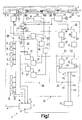
- FIG. 1 schematically shows a dictation device for recording and reproducing voice signals on a recording medium designed as a magnetic tape, which contains a system for recording and evaluating marking signals, with which marking signals of three different types can be recorded and evaluated.
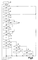
- 2 shows a flow diagram of a program sequence for generating these marking signals of three different types in the device according to FIG. 3 shows the signal formation of a marking signal of a first type generated according to the program flow according to FIG. 2.
- FIG. 4 shows the signal formation of a marking signal of a second type generated according to the program flow according to FIG. 2.
- FIG. 5 shows the signal formation of a Marking signals of a third type generated according to the program flow according to FIG. 2.
- FIG. 6 shows a flow diagram of a program flow for evaluating marking signals of the three different types according to FIGS. 3, 4 and 5.
- FIG. 7 shows a modification of the exemplary embodiment according to FIG .1 a part of a recording device for marking signals of a second system according to the invention for recording and evaluating marking signals.
- 8 shows, in a modification of the exemplary embodiment according to FIG. 1, part of an evaluation device for marking signals of a third system according to the invention for recording and evaluating marking signals.
- FIG. 9 shows a further marking signal of the third type, which can be generated with a system according to the invention for recording and evaluating marking signals.
- the 10 shows yet another marking signal of the third type that can be generated with a system according to the invention for recording and evaluating marking signals.
- FIG. 1 schematically shows the parts of a table dictation device 1 that are essential to the invention, with which preferably voice signals can be recorded on a magnetic tape 2 accommodated in a cassette (not shown) and can be scanned and reproduced by the magnetic tape.
- a part of the magnetic tape 2 is shown in FIG.
- Provided on the magnetic tape 2 are two tracks 3 and 4, indicated by dash-dotted lines, which can be scanned with the aid of a recording / reproducing magnetic head 5 in the opposite directions of travel of the magnetic tape for recording and reproducing signals.
- the magnetic tape 2 is moved in a direction indicated by an arrow 6.
- This movement of the magnetic tape 2 takes place with the aid of a schematically indicated motorized tape drive device 7, which drives the magnetic tape 2 via winding mandrels, which are coupled with winding cores in a cassette, as is symbolically indicated in FIG. 1 by a dashed line 8.
- the tape drive device 7 has three control inputs 9, 10 and 11, which can be controlled by a control stage 12, in order to switch the tape drive device 7 into three different operating modes, in which the tape with simple normal travel speed in the direction of arrow 6, with 20 times travel speed in Direction of arrow 6 or is driven at twenty times the speed of travel against the direction of arrow 6.
- the tape drive device 7 has a control input 13 via which it can be switched off in order to stop driving the magnetic tape 2.
- control stage 12 is part of a microprocessor 14, which is indicated schematically in FIG. 1 with a dash-dotted line.
- the control stage 12 can be used to determine on the one hand via query inputs 15 whether and which key of a key set 16 has been actuated to switch on operating modes or operating functions of the device.
- the control stage 12 gives control outputs 17 of the same control signals for controlling device parts, such as the belt drive device 7.
- a microphone 18 which can be plugged into the device 1 is connected to the device 1.
- the output signals of the microphone 18 are fed to a recording amplifier circuit 19, the output signals of which are fed to a summing stage 20.
- the output signals of the summing stage 20 are fed to a recording / reproduction changeover switch 21 which, in the switching position shown in full line in FIG. 1, which it assumes for recording signals, feeds the signals fed to it to the magnetic head 5.
- voice signals corresponding to spoken dictations can be recorded on the magnetic tape 2.
- an oscillator 22 is activated, which is a bias or. Deletes the magnetic head 5 when recording signals.
- the recording / playback switch 21 and the oscillator 22 each have a control input 23 and 24, respectively, via which the two can be controlled by the control stage 12.
- the changeover switch 21 is switched from the control stage 12 to its switch position shown in FIG. 1 with a broken line.
- voice signals sampled from the magnetic tape 2 are fed to a reproduction amplifier circuit 25 with the magnetic head 5, the output signals of which are fed to a loudspeaker 26 for acoustic reproduction.
- the output signals of the reproduction amplifier circuit 25 can also be fed to headphones, via which a typist can listen to the stored dictations for writing them down.
- FIG. 1 schematically shows that a first dictation 27 and a second dictation 28 are stored on the magnetic tape 2.
- a dictation device it has proven to be very useful and practical to be able to mark certain locations of the stored dictations or the dictations themselves, if desired, with marking signals.
- marking signals are indicated symbolically in FIG. 1 and designated by the reference symbols M1, M2 and M3.
- there are three different types of marking signals on the device Magnetic tape 2 can be stored and then evaluated again.
- the device 1 has a system 29 for recording and evaluating marking signals M1, M2 and M3 which are recordable and storable on the magnetic tape and can be scanned from the magnetic tape and can be distinguished from one another.
- the device 1 has a button A for triggering the generation and recording of a marking signal M1 of a first type.
- the device 1 has a button B.
- the triggering of the generation and recording of a marking signal M3 of a third type can be triggered, as will be described in more detail below, by pressing the A key twice in succession within a predetermined time period. In this way it is achieved that no separate key is required to trigger the generation and recording of a marking signal of the third type.
- a key C is provided for triggering the evaluation of marking signals M1 of the first type, a key D for triggering the evaluation of marking signals M2 of the second type and a key E for triggering the evaluation of marking signals M3 of the third type.
- the key set 16 also has further keys which are used, for example, to switch on the "recording" operating mode, the "playback” operating mode, the "fast forward” operating mode and the “fast reverse” operating mode and the like.
- the system 29 for recording and evaluating marking signals has a recording device 30, schematically outlined in FIG. 1 with a dashed line, for recording the marking signals to be stored, and an evaluation device 31, likewise outlined in FIG. 1, for evaluating the scanned marking signals.
- the recording device 30 contains a generator device 32 for generating the marking signals to be stored.
- the evaluation device 31 contains a detector device 33 for detecting the scanned marking signals.
- the generator device 32 consists of a first generator stage 34 for generating a first signal which has a first frequency and a second generator stage 35 for generating a second signal which has a second frequency.
- the frequency of the first signal is included 40 Hz and the frequency of the second signal selected at 1500 Hz.
- the two generator stages 34 and 35 are implemented with the aid of the microprocessor 14, the same emitting pulse-shaped signals.
- the pulse-shaped signals of the generator stages 34 and 35 are each fed to a filter stage 36 or 37, which is designed as a low-pass filter and converts the pulse-shaped signals into sinusoidal signals S1 and S2, which are fed to the summing stage 20, via which the signals S1 and S2 are sent to the changeover switch 21 and the magnetic head 5 are supplied.
- the generator device 32 also has a first timing stage Z1 and a second timing stage Z2.
- the occurrence time period for the first signal S1 can be determined with the first time control stage Z1.
- the time period for the second signal S2 can be determined with the second time control stage Z2.
- the two time control stages Z1 and Z2 are also implemented with the aid of the microprocessor 14, the same being designed as time window stages, as can be seen from the following description of the flowchart according to FIG.
- the detector device 33 has two filter stages 38 and 39, to which the signals sampled with the magnetic head 5 are fed via the changeover switch 21.
- the evaluation of the marking signals takes place at a speed of movement of the magnetic tape 2 which is 20 times higher than the recording of the marking signals.
- the filter stage 38 With the filter stage 38, the signal S1 'corresponding to the first signal S1' can be separated from the signal mixture supplied to it at a frequency of 800 Hz.
- the detector device 33 also has a detector stage 40 downstream of the filter stage 38 for detecting the signal S1 ′ corresponding to the first signal and a detector stage 41 downstream of the filter stage 39 for detection of the signal S2 corresponding to the second signal S2 '.
- the two detector stages 40 and 41 are formed, for example, by rectifier stages, which each emit a predetermined output signal D1 or D2 at their output when the corresponding signal S1 'or S2' occurs.
- the detector device 33 has a time measurement stage Z3 following the detector stage 40 and a time measurement stage Z4 following the detector stage 41.
- the occurrence period of the signal S1 ′ or S2 ′ corresponding to the first signal S1 or the second signal S2 can be measured, which in the present device is one twentieth of the occurrence period of the first signal S1 or the second signal S2 is.
- the two time measuring stages Z3 and Z4 are likewise realized with the microprocessor 14 and formed by time counting stages, as can be seen from the following description of the flow chart according to FIG.
- the two time measuring stages Z3 and Z4 are followed by a logic stage 42 which is also implemented with the microprocessor 14 and which the time measuring stages Z3 and Z4 supply different measured values C3 and C4 depending on the measured time span of the signal S1 'and S2' and which depend on them supplied measured values C3 and C4 generated detection signals H1, H2 and H3, which correspond to the marking signals M1, M2 and M3 scanned by the magnetic tape 2.
- the logic stage 42 has three outputs P1, P2 and P3, to which a gate stage 43 is connected, the output of which is connected to the control input 13 of the belt drive device 7 and which, when a detection signal H1, H2 or H3 occurs, at one of the outputs P1, P2 or P3 outputs a control signal to the control input 13 which switches off the tape drive device 7, the driving of the magnetic tape 2 being ended.
- a program sequence in the microprocessor 14 of the device 1 for generating the marking signals M1, M2 and M3 of the three different types with the aid of the system 29 for recording and evaluating marking signals is described below with reference to the flowchart shown in FIG.
- this program flow is started.
- block 45 it is checked whether the key A has been pressed. If so, then at block 46 there will be a time window started for the time period T1 of 500 msec, for example. It is then checked at block 47 whether key A has been pressed a second time. If this is the case, the operator of the device has given the command to generate a marking signal M3 of the third type and to record it on the magnetic tape.
- an operating mode "recording a marking signal” is switched on, in which the tape drive device 7 drives the magnetic tape 2 in the direction of arrow 6 at a simple normal travel speed, the recording / playback switch 21 into that in FIG. 1 with a full one Line switch position shown is switched and the oscillator 22 is turned on to generate a bias signal.
- a time window stage forming the time control stage Z1 is switched on for a time period T of, for example, 650 msec and practically at the same time a time window stage provided as the time control stage Z2 for the time period T / 2, that is to say for 325 msec.
- the generator stage 34 for generating the first signal S1 from the time window stage Z1 for the period T and practically at the same starting time the generator stage 35 for generating the second signal S2 from the time window stage Z2 for the period T / 2 are activated.
- pulse-shaped signals are generated which are converted by filter stages 36 and 37 into sinusoidal signals S1 and S2.
- a marking signal M3 of the third type is generated, as shown in Fig.5.
- the program flow continues at block 51, which is representative of a large number of further program steps. After execution of these program steps according to block 51, the program flow according to FIG. 2 is continued again at block 45.
- the time period T1 of the time window specifies the time period within which the key A must be pressed twice in order to execute the command for generating and recording a marking signal M3 of the third type to give. If the time period T1 has not expired, the program flow continues again at block 47.
- the operating mode becomes analogous to block 48 at block 53 "Recording a marking signal" switched on.
- the time window stage forming time control stage Z1 is switched on for the time period T of 650 msec, and practically at the same time the time window stage forming time control stage Z2 is set to the value zero.
- generator stage 34 is activated by time window stage Z1 for time period T, whereas generator stage 35 is not activated by time window stage Z2 in this case.
- a marking signal M1 of the first type is generated, as shown in FIG. After block 55, the program flow continues at block 51.
- an identification signal is subsequently stored at block 63 for which of these three keys C, D and E has been actuated.
- the operating mode "evaluating a marking signal” is switched on, the magnetic tape 2 first being driven by the tape drive device 7 at twenty times the speed of travel against the direction of the arrow 6 until the start of the magnetic tape 2 is opposite the magnetic head 5, and then the tape drive device 7 drives the magnetic tape 2 in the direction of arrow 6 at twenty times the speed of travel and the recording / playback switch 21 is switched to its switching position shown in FIG. 1 with a broken line. It is then checked at block 65 whether there is an output signal D1 at the output of the detector stage 40.
- a time counting stage provided as a time measuring stage Z3 is started at block 66. It is then checked at block 67 whether there is an output signal D2 at the output of the detector stage 41. If this is not the case, that is, if no signal S2 'is scanned from the magnetic tape, then a time counter stage provided as a time measuring stage Z4 is set to the value zero at block 68, the set counter reading zero then being stored as measured value C4 in the time measuring stage Z4 .
- an output signal D2 is determined at block 67, which means that a signal S2 'is scanned from the magnetic tape 2
- Block 69 started the time counting stage provided as time measuring stage Z4. It is then checked at block 70 whether the output signal D2 of the detector stage 41 is still present. If this is the case, the program flow continues again at block 70, as long as the output signal D2 is present. If it is determined at block 70 that the output signal D2 of the detector stage 41 is no longer present, the time counting stage provided as the time measuring stage Z4 is then stopped at block 71, the counter reading reached then being stored as the measured value C4 in the time measuring stage Z4.
- the program flow continues at block 72, in which it is checked whether the output signal D1 of the detector stage 40 is still present. If this is the case, the program flow continues again at block 72, as long as the output signal D1 is present. If it is determined at block 72 that the output signal D1 of the detector stage 40 is no longer present, then the time counting stage provided as the time measuring stage Z3 is stopped at block 73, the counter reading reached then being stored as the measured value C3 in the time measuring stage Z3.
- the quotient is formed from the counter readings C4 and C3 of the time counter stages Z4 and Z3. It is then checked at block 75 whether this quotient has the value zero. If this is the case, which means that a marking signal M1 of the first type has been sampled, a check is made at block 76 as to whether the key C which has to be pressed to find and evaluate a marking signal M1 of the first type has been pressed. The check at block 76 is carried out by checking the identification signal stored at block 63. If it is determined at block 76 that key C has not been actuated, then the program flow continues at block 62.
- the logic stage 42 outputs a detection signal H1 at its output P1.
- This detection signal H1 indicates that a marking signal M1 of the first type has been evaluated as desired.
- This detection signal H1 is fed via the gate stage 43 to the control input 13 of the belt drive device 7. whereby this is switched off when such a marker signal is found.
- the detection signal H1 could also be used differently, for example in that it is fed to an optical display device for indicating the presence of a marking signal of the first type.
- the logic stage 42 outputs a detection signal H3 at its output P3.
- This detection signal H3 indicates that a marking signal M3 of the third type has been evaluated as desired.
- This detection signal H2 indicates that a marking signal M2 of the second type has been evaluated as desired.
- the program flow continues at block 62. In the event that it is determined at block 81 that the key D has not been pressed either, then it can be assumed that an evaluation process for marking signals was triggered by an operating error, in which case the generation of a detection signal by the logic stage 42 is prevented, and therefore the program flow continues at block 62.
- marking signals of three different types can be recorded in a particularly simple manner on the magnetic tape 2 and can be evaluated by the magnetic tape after they have been scanned.
- the marker signal M1 of the first type consists only of the signal S1, which has a frequency of 40 Hz and occurs in the time T
- the marker signal M2 of the second type and that Marking signal M3 of the third type consists of the first signal S1, which has a frequency of 40 Hz, and the second signal S2, which has a frequency of 1500 Hz
- the time of occurrence of the first signal S1 in these two marking signals M1 and M2 is equal to T.
- the difference between the marker signal M2 of the second type and the marker signal M3 of the third type lies in the fact that the occurrence period of the second signal S2 is only T / 2 for the marker signal M3 of the third type, whereas it is T for the marker signal M2 of the second type. This ensures that the marking signals of the second and third types can also be clearly and correctly distinguished from one another.
- the marking signals of the second type and the third type both consist of the same signals S1 and S2, it is achieved that the marking signals of these two types also with an evaluation device that does not have time measuring stages for the occurrence time periods of the signals S1 and S2 corresponding to the signals S1 and S2 and S2 ', but only detector stages with which the occurrence of these corresponding signals S1' and S2 'can be determined per se, can be detected.
- marking signals of the second type and marking signals of the third type cannot be differentiated from one another according to their type, but the presence of each of these marking signals can very well be determined. Since to evaluate the Marking signals of the quotient, that is, the ratio of the measured values of the time measuring stages is used, the evaluation is advantageously independent of the speed of travel of the magnetic tape when scanning the marking signals.
- Marking signals of the three types mentioned above are recorded by a dictator for the identification of dictations or dictation locations on the magnetic tape.
- Marking signals of the first type each mark, for example, the end of the dictation of a dictation stored on the magnetic tape, for which the dictator has not given any particular information, wishes or requirements regarding the evaluation by a typist.
- Such a marking signal of the first type is then recorded on the magnetic tape if a dictation end of such a dictation stored on the magnetic tape is opposite the recording / reproducing magnetic head.
- Marking signals of the second type each indicate, for example, a dictation location of a dictation stored on the magnetic tape, to which a dictator wants or has given a specific instruction, such as a dictation insertion, a dictation correction or a request relating to the dictation or also a wish that is independent of the dictation , which can also be stored on the magnetic tape or on a separate storage element, such as another magnetic tape or a note.
- Marking signals of the third type identify, for example, the end of the dictation or the beginning of a dictation stored on the magnetic tape, to which the dictator has assigned particular importance or priority over time with regard to the evaluation by a typist; such dictations are called priority dictations.
- a system according to the invention for recording and evaluating marking signals as described above can also be used to store a further marking signal of the third type or also a plurality of such marking signals of the third type on the magnetic tape.
- a further marking signal of the third type can consist of the first signal S1 with a frequency of 40 Hz and with an occurrence time period T and from the second signal S2 with a frequency of 1500 Hz and with an occurrence time period T / 4 be composed.
- Such a further marking signal of the third type can be used, for example, to mark the end of a group of related dictations stored on the magnetic tape, this group of dictations originating, for example, from a single dictator or this group of dictations relating to a related subject area.
- Such a group of related dictations can also be formed in that these dictations are transmitted over a telephone network to a dictation machine that can be connected to the telephone network during a single uninterrupted call, the recording then automatically taking place in this dictation machine after the transmission of these dictations has ended and the call has ended of such a further marking signal of the third type is triggered.
- the generator stages 34 and 35 and the timing stages Z1 and Z2 of the generator device 32 of the recording device 30 are not used, as a modification to the system according to FIG of the microprocessor 14 with Kilfe of discrete components.
- the two generator stages 34 and 35 are designed as sine-wave generators which continuously emit the first signal S1 and the second signal S2.
- the two timing stages Z1 and Z2 are designed as gate circuits which can be controlled by the control stage 12 and which let through the signals S1 and S2 emitted by the generator stages 34 and 35 for a respective time period determined by the control stage 12.
- the signals S1 and S2 passed by the timing stages Z1 and Z2 are fed directly to the summing stage 20, from which the signals S1 and S2 are fed to the recording / reproducing magnetic head for recording on the magnetic tape. In this case, there is no need to provide filter stages for the signals S1 and S2 before they are fed to the summing stage 20.
- the detector device has 33 of the evaluation device 31 has a different structure than the system according to FIG.
- the detector stage 40 with which the signal S1 'corresponding to the signal S1' can be detected, is not followed by a time measuring stage.
- the output signal D1 of the detector stage 40 is fed directly to the logic stage 42 in this detector device 33.
- the detection signals H1, H2 and H3 are not supplied to a gate stage, but rather to an indicator lamp L1, L2 or L3, which are briefly illuminated, for example, to indicate the presence of a marker of the first, second or third type.
- FIG. 4 An example of a further marking signal M4 of the third type is shown in FIG.
- This marking signal M4 is composed of the first signal S1 with a frequency of 40 Hz, for which an occurrence period T is selected, and from the second signal S2 with a frequency of 1500 Hz, for which an occurrence period T / 2 is selected, however, the time of occurrence of the second signal S2 is shifted by a time T / 4 compared to the time of appearance of the first signal S1.
- Such a marker signal is advantageous with regard to its evaluation in that when evaluating the same the time of switching on the time measuring stage for measuring the time of occurrence of the signal S2 corresponding to the second signal is uncritical in relation to switching on the time measuring stage for measuring the Occurrence of the signal S1 ′ corresponding to the first signal S1.
- the first signal S1 again extends over the occurrence time period T and the second signal S2 over an occurrence time period T / 2, which, however, consists of two parts, each with an occurrence time period of T / 4 composed, which are separated by an occurrence gap of T / 2.
- This marker signal has the advantage that despite different lengths of occurrence of the two signals S1 and S2, the two signals S1 and S2 have the same occurrence and the same end time, so that when they are evaluated, the time measuring stages for measuring the occurrence of those corresponding to the signals S1 and S2 Signals S1 'and S2' can be started and stopped at the same time.
- a system for recording and evaluating marking signals for example, its recording device for marking signals can be provided in a separate recording device that is designed only for recording dictations, and its evaluation device in a separate playback device that is designed only for playing back dictations.
- Such a system for recording and reproducing marking signals can be used not only in a dictation system for recording and reproducing dictations, but also in other systems for recording and reproducing other information signals. Marking signals can be recorded when the "recording" mode is activated in a device, or when the "playback” mode is activated in a device, or when the mode "Stop" is activated in a device.
- the marking signals do not have to be recorded together with the information signals in the same track on a recording medium, but can also be recorded in a separate track.
- Other signal compositions are also possible as marking signals of the third type.
- such a further marking signal of the third type from the first signal S1 with an occurrence period T and the second signal S2 with an occurrence period 2T.
- Such a further marking signal of the third type can also be composed of the first signal S1 with an occurrence period T / 3 and the second signal S2 with an occurrence period T.
- the first signal S1 therefore has an occurrence time period which is different from the value T.
Landscapes
- Recording Or Reproducing By Magnetic Means (AREA)
- Signal Processing For Digital Recording And Reproducing (AREA)
- Indexing, Searching, Synchronizing, And The Amount Of Synchronization Travel Of Record Carriers (AREA)
Claims (7)
- Système (1) d'enregistrement et d'évaluation de signaux de repérage (M1, M2) différenciables les uns des autres, qui peuvent être mémorisés sur un support d'enregistrement (2) et extraits par lecture de celuici, comprenant un dispositif d'enregistrement (30) pour enregistrer les signaux de repérage à mémoriser (M1, M2) et un dispositif d'évaluation (29) pour évaluer les signaux de repérage lus (M1, M2), le dispositif d'enregistrement (30) comportant un dispositif générateur (32) pour produire les signaux de repérage à mémoriser (M1, M2) et le dispositif d'évaluation (29) comportant un dispositif de détection (33) pour détecter les signaux de repérage (M1, M2) lus, le dispositif générateur (32) comprenant un premier étage générateur (34, 36) pour produire un premier signal (S1) qui présente une première fréquence, un deuxième étage générateur (35, 37) pour produire un deuxième signal (S2) qui présente une deuxième fréquence, la première et la deuxième fréquences étant différentes, un premier étage de synchronisation (Z1) qui permet de fixer l'intervalle de temps d'apparition du premier signal (S1), et un deuxième étage de synchronisation (Z2) qui permet de fixer l'intervalle de temps d'apparition du deuxième signal (S2), et dans lequel, pour produire un signal de repérage d'un premier type (M1) qui n'est constitué que du premier signal (S1), le premier étage de synchronisation (Z1) établit pour l'intervalle de temps d'apparition du premier signal (S1) une valeur prédéterminée T et simultanément le deuxième étage de synchronisation (Z2) établit pour l'intervalle de temps d'apparition du deuxième signal (S2) la valeur zéro, et pour produire un signal de repérage d'un deuxième type (M2) constitué du premier signal (S1) et du deuxième signal (S2), le premier étage de synchronisation (Z1) établit pour l'intervalle de temps d'apparition du premier signal (S1) et, simultanément, le deuxième étage de synchronisation (Z2) établit pour l'intervalle de temps d'apparition du deuxième signal (S2) chaque fois la valeur T, et le dispositif de détection (33) comprend un premier étage de détection (38, 40) pour détecter un signal (S1') correspondant au premier signal (S1) extrait par lecture du support d'enregistrement (2) et un deuxième étage de détection (39, 41) pour détecter un signal (S2') correspondant au deuxième signal (S2) extrait par lecture du support d'enregistrement (2), les deux dispositifs délivrant, à l'apparition du signal correspondant concerné (S1′, S2′), respectivement, un signal de sortie (D1', D2), et un étage logique (42) suivant les deux étages de détection (38-41), qui produit et délivre, en fonction des signaux de sortie (D1, D2) des deux étages de détection, les signaux de détection (H1, H2) correspondant aux signaux de repérage (M1, M2) extraits par lecture du support d'enregistrement (2), caractérisé en ce que, pour produire au moins un signal de repérage d'un troisième type (M3) constitué du premier signal (S1) et du deuxième signal (S2), au moins un des deux étages de synchronisation (Z1, Z2) fixe l'intervalle de temps d'apparition, qui peut être fixé par ses soins, pour le signal concerné sur au moins une valeur différente de T, et le dispositif de détection (33) comprend, en plus des deux étages de détection (38-41) pour détecter les deux signaux (S1', S2') correspondant au premier signal (S1) et au deuxième signal (S2) et extraits par lecture du support d'enregistrement (2) pour au moins un de ces deux signaux correspondants, qui correspond à l'un des deux signaux, pour lequel, avec l'un des deux étages de synchronisation (Z1, Z2), au moins un intervalle de temps d'apparition différent de la valeur T peut être fixé, un étage de mesure du temps (Z3, Z4) pour mesurer l'intervalle de temps d'apparition d'au moins ce premier signal correspondant, qui achemine selon l'intervalle de temps d'apparition mesuré différentes valeurs de mesure de l'étage logique (42) pour produire les signaux de détection (H1-H3) correspondant aux signaux de repérage (M1-M3) extraits par lecture du support d'enregistrement (2).
- Système selon la revendication 1, caractérisé en ce que, pour produire au moins un signal de repérage du troisième type (M3), le premier étage de synchronisation (Z1) fixe, pour l'intervalle de temps d'apparition du premier signal (S1), la valeur T et, simultanément, le deuxième étage de synchronisation (Z2) fixe pour l'intervalle de temps d'apparition du deuxième signal (S2), au moins une valeur différente de T.
- Système selon la revendication 2, caractérisé en ce que, pour produire un signal de repérage du troisième type (M3), le premier étage de synchronisation (Z1) fixe, pour l'intervalle de temps d'apparition du premier signal (S1), la valeur T et, simultanément, le deuxième étage de synchronisation (Z2) fixe, pour l'intervalle de temps d'apparition du deuxième signal (S2), la valeur T/2.
- Système selon l'une quelconque des revendications précédentes, caractérisé en ce que, pour la production d'au moins un signal de repérage du troisième type (M3), les deux étages de synchronisation (Z1, Z2) fixent le même instant de départ pour les intervalles de temps d'apparition des deux signaux (S1, S2).
- Système selon l'une quelconque des revendications précédentes, caractérisé en ce que les deux étages de synchronisation (Z1, Z2) activent les deux étages générateurs (34-37) pour produire le premier signal (S1) et le deuxième signal (S2).
- Système selon l'une quelconque des revendications précédentes avec un premier organe de commande (A) pour déclencher la production et l'enregistrement d'un signal de repérage du premier type (M1) et avec un deuxième organe de commande (B) pour déclencher la production et l'enregistrement d'un signal de repérage du deuxième type (M2), caractérisé en ce que la production et l'enregistrement d'au moins un signal de repérage du troisième type (M3) peuvent être déclenchés par l'actionnement successif d'un des deux organes de commande (A, B), au moins à deux reprises dans un intervalle de temps prédéterminé.
- Système selon l'une quelconque des revendications précédentes, caractérisé en ce que le dispositif de détection (33) pour le signal (S1′) correspondant au premier signal (S1) extrait par lecture du support d'enregistrement (2) contient un premier étage de mesure du temps (Z3) pour mesurer l'intervalle de temps d'apparition de ce signal correspondant et pour le signal (S2′) correspondant au deuxième signal (S2) extrait par lecture du support d'enregistrement (2), un étage de mesure du temps (Z4) pour mesurer l'intervalle de temps d'apparition de ce signal correspondant, étages qui envoient tous deux les valeurs de mesure qu'ils ont déterminées à l'étage logique (42), et l'étage logique produit les signaux de détection (H1-H3) correspondant aux signaux de repérage (M1-M3) lus en fonction du rapport des valeurs de mesure qui lui sont acheminées.
Applications Claiming Priority (2)
| Application Number | Priority Date | Filing Date | Title |
|---|---|---|---|
| AT2543/88 | 1988-10-13 | ||
| AT2543/88A AT393569B (de) | 1988-10-13 | 1988-10-13 | System zum aufzeichnen und auswerten von markiersignalen |
Publications (3)
| Publication Number | Publication Date |
|---|---|
| EP0364041A2 EP0364041A2 (fr) | 1990-04-18 |
| EP0364041A3 EP0364041A3 (fr) | 1993-04-21 |
| EP0364041B1 true EP0364041B1 (fr) | 1995-01-11 |
Family
ID=3536152
Family Applications (1)
| Application Number | Title | Priority Date | Filing Date |
|---|---|---|---|
| EP89202536A Expired - Lifetime EP0364041B1 (fr) | 1988-10-13 | 1989-10-09 | Système d'enregistrement et d'utilisation des repères |
Country Status (6)
| Country | Link |
|---|---|
| US (1) | US5126888A (fr) |
| EP (1) | EP0364041B1 (fr) |
| JP (1) | JPH02149960A (fr) |
| AT (1) | AT393569B (fr) |
| DE (1) | DE58908877D1 (fr) |
| HK (1) | HK66696A (fr) |
Families Citing this family (4)
| Publication number | Priority date | Publication date | Assignee | Title |
|---|---|---|---|---|
| AT395787B (de) * | 1989-05-26 | 1993-03-25 | Philips Nv | System zum auswerten von markierungen |
| US5689610A (en) * | 1994-06-20 | 1997-11-18 | Eastman Kodak Company | Method of making an index print having an indicator of substantially where an image is stored on a motion picture image recording medium |
| IL122139A (en) * | 1996-03-11 | 2001-04-30 | Koninkl Philips Electronics Nv | Install the article for storing speech signals |
| US20030078156A1 (en) * | 2001-08-23 | 2003-04-24 | Lowden Richard A. | Creep resistant refractory with controlled optical emission |
Family Cites Families (7)
| Publication number | Priority date | Publication date | Assignee | Title |
|---|---|---|---|---|
| JPS5136617B2 (fr) * | 1972-07-25 | 1976-10-09 | ||
| US3882545A (en) * | 1972-11-15 | 1975-05-06 | Lanier Electronic Lab Inc | Apparatus and method for detecting tone signals occuring within a predetermined frequency range |
| US4007491A (en) * | 1973-08-27 | 1977-02-08 | Lanier Business Products, Inc. | Dictation-transcription method and system |
| US4378577A (en) * | 1980-08-15 | 1983-03-29 | Dictaphone Corporation | Method and apparatus for recording and detecting indicating signals in a recording and/or reproducing device |
| AT375486B (de) * | 1982-12-07 | 1984-08-10 | Philips Nv | System zum aufzeichnen und/oder auswerten von zwei markiersignalen |
| US4677501A (en) * | 1985-01-14 | 1987-06-30 | Dictaphone Corporation | Method and apparatus for displaying indications of instructions in previously recorded messages |
| US4794474A (en) * | 1986-08-08 | 1988-12-27 | Dictaphone Corporation | Cue signals and cue data block for use with recorded messages |
-
1988
- 1988-10-13 AT AT2543/88A patent/AT393569B/de not_active IP Right Cessation
-
1989
- 1989-08-17 US US07/395,127 patent/US5126888A/en not_active Expired - Fee Related
- 1989-10-09 EP EP89202536A patent/EP0364041B1/fr not_active Expired - Lifetime
- 1989-10-09 DE DE58908877T patent/DE58908877D1/de not_active Expired - Fee Related
- 1989-10-11 JP JP1263126A patent/JPH02149960A/ja active Pending
-
1996
- 1996-04-18 HK HK66696A patent/HK66696A/xx not_active IP Right Cessation
Also Published As
| Publication number | Publication date |
|---|---|
| EP0364041A3 (fr) | 1993-04-21 |
| EP0364041A2 (fr) | 1990-04-18 |
| HK66696A (en) | 1996-04-26 |
| JPH02149960A (ja) | 1990-06-08 |
| US5126888A (en) | 1992-06-30 |
| AT393569B (de) | 1991-11-11 |
| ATA254388A (de) | 1991-04-15 |
| DE58908877D1 (de) | 1995-02-23 |
Similar Documents
| Publication | Publication Date | Title |
|---|---|---|
| DE69330173T2 (de) | Aufzeichnungs- und Wiedergabegerät | |
| DE2702780C2 (de) | Bandschnittsteuereinrichtung mit zwei Videomagnetbandgeräten | |
| DE4226420C2 (de) | Steuerschaltkreis zur komprimierten Aufzeichnung und Wiedergabe einer Vielzahl von Viedosignalen | |
| DE3943353A1 (de) | Pausesteuerung fuer eine aufzeichnungs/wiedergabevorrichtung | |
| DE3600728A1 (de) | Verfahren und vorrichtung zur sichtanzeige von anweisungsangaben in voraufgezeichneten nachrichten | |
| DE3020882A1 (de) | Verfahren und vorrichtung zum edieren von digitalsignalen | |
| DE3726367C2 (de) | Markierungssignale und Markierungsdatenblöcke für den Einsatz mit aufgenommenen Mitteilungen | |
| AT396043B (de) | Automatisches telefonanrufbeantwortergeraet | |
| DE2814721A1 (de) | Steuereinrichtung fuer magnetische aufzeichnungs- und/oder wiedergabegeraete | |
| DE3602068C2 (fr) | ||
| EP0110483B1 (fr) | Système d'enregistrement et/ou de détection de deux signaux de marquage | |
| DE3016059A1 (de) | Bandstellensucher fuer ein pcm-aufzeichnungs- und -wiedergabe-geraet | |
| EP0212389A1 (fr) | Récepteur de télévision | |
| EP0364041B1 (fr) | Système d'enregistrement et d'utilisation des repères | |
| DE2829476A1 (de) | Verfahren und vorrichtung zur audiovisuellen wiedergabe von informationen | |
| DE2320593A1 (de) | Einrichtung zum selbsttaetigen heraussuchen von auf einem magnetband aufgezeichneten ton (stuecken) in einem magnetbandgeraet mittels kodierter auf dem band aufgezeichneter identifikationssignale | |
| DE2832899A1 (de) | Verfahren und vorrichtung zur audio-visuellen wiedergabe von informationen | |
| DE2646053A1 (de) | Elektrische steuerschaltung fuer eine magnetbandgesteuerte glasschneidemaschine | |
| DE3401421A1 (de) | Adressendatenuebertagungsvorrichtung | |
| DE2837598A1 (de) | Steuereinrichtung | |
| DE3222487A1 (de) | Bandkassettenrekorder | |
| DE2822363A1 (de) | Bandsystem | |
| DE3124858C2 (de) | Radio-Kassettenrecorder-Kombination | |
| EP0503519B1 (fr) | Enregistreur vidéo avec registre de mémorisation de la table des matières d'une pluralité de cassettes magnétiques | |
| DE2463114C2 (de) | Steuerschaltung für eine Cassetten-Wechselvorrichtung in einer Zentraldiktieranlage |
Legal Events
| Date | Code | Title | Description |
|---|---|---|---|
| PUAI | Public reference made under article 153(3) epc to a published international application that has entered the european phase |
Free format text: ORIGINAL CODE: 0009012 |
|
| AK | Designated contracting states |
Kind code of ref document: A2 Designated state(s): CH DE FR GB IT LI |
|
| PUAL | Search report despatched |
Free format text: ORIGINAL CODE: 0009013 |
|
| AK | Designated contracting states |
Kind code of ref document: A3 Designated state(s): CH DE FR GB IT LI |
|
| 17P | Request for examination filed |
Effective date: 19931018 |
|
| 17Q | First examination report despatched |
Effective date: 19940302 |
|
| GRAA | (expected) grant |
Free format text: ORIGINAL CODE: 0009210 |
|
| AK | Designated contracting states |
Kind code of ref document: B1 Designated state(s): CH DE FR GB IT LI |
|
| PG25 | Lapsed in a contracting state [announced via postgrant information from national office to epo] |
Ref country code: IT Free format text: LAPSE BECAUSE OF FAILURE TO SUBMIT A TRANSLATION OF THE DESCRIPTION OR TO PAY THE FEE WITHIN THE PRESCRIBED TIME-LIMIT;WARNING: LAPSES OF ITALIAN PATENTS WITH EFFECTIVE DATE BEFORE 2007 MAY HAVE OCCURRED AT ANY TIME BEFORE 2007. THE CORRECT EFFECTIVE DATE MAY BE DIFFERENT FROM THE ONE RECORDED. Effective date: 19950111 |
|
| REF | Corresponds to: |
Ref document number: 58908877 Country of ref document: DE Date of ref document: 19950223 |
|
| GBT | Gb: translation of ep patent filed (gb section 77(6)(a)/1977) |
Effective date: 19950302 |
|
| ET | Fr: translation filed | ||
| PG25 | Lapsed in a contracting state [announced via postgrant information from national office to epo] |
Ref country code: LI Effective date: 19951031 Ref country code: CH Effective date: 19951031 |
|
| PLBE | No opposition filed within time limit |
Free format text: ORIGINAL CODE: 0009261 |
|
| STAA | Information on the status of an ep patent application or granted ep patent |
Free format text: STATUS: NO OPPOSITION FILED WITHIN TIME LIMIT |
|
| 26N | No opposition filed | ||
| REG | Reference to a national code |
Ref country code: CH Ref legal event code: PL |
|
| PGFP | Annual fee paid to national office [announced via postgrant information from national office to epo] |
Ref country code: DE Payment date: 19961218 Year of fee payment: 8 |
|
| PGFP | Annual fee paid to national office [announced via postgrant information from national office to epo] |
Ref country code: GB Payment date: 19970930 Year of fee payment: 9 |
|
| PGFP | Annual fee paid to national office [announced via postgrant information from national office to epo] |
Ref country code: FR Payment date: 19971021 Year of fee payment: 9 |
|
| PG25 | Lapsed in a contracting state [announced via postgrant information from national office to epo] |
Ref country code: DE Free format text: LAPSE BECAUSE OF NON-PAYMENT OF DUE FEES Effective date: 19980701 |
|
| REG | Reference to a national code |
Ref country code: FR Ref legal event code: CD |
|
| PG25 | Lapsed in a contracting state [announced via postgrant information from national office to epo] |
Ref country code: GB Free format text: LAPSE BECAUSE OF NON-PAYMENT OF DUE FEES Effective date: 19981009 |
|
| GBPC | Gb: european patent ceased through non-payment of renewal fee |
Effective date: 19981009 |
|
| PG25 | Lapsed in a contracting state [announced via postgrant information from national office to epo] |
Ref country code: FR Free format text: LAPSE BECAUSE OF NON-PAYMENT OF DUE FEES Effective date: 19990630 |
|
| REG | Reference to a national code |
Ref country code: FR Ref legal event code: ST |