EP0364043B1 - Bildprojektionsanordnung - Google Patents
Bildprojektionsanordnung Download PDFInfo
- Publication number
- EP0364043B1 EP0364043B1 EP89202545A EP89202545A EP0364043B1 EP 0364043 B1 EP0364043 B1 EP 0364043B1 EP 89202545 A EP89202545 A EP 89202545A EP 89202545 A EP89202545 A EP 89202545A EP 0364043 B1 EP0364043 B1 EP 0364043B1
- Authority
- EP
- European Patent Office
- Prior art keywords
- image
- colour
- image display
- sub
- beams
- Prior art date
- Legal status (The legal status is an assumption and is not a legal conclusion. Google has not performed a legal analysis and makes no representation as to the accuracy of the status listed.)
- Expired - Lifetime
Links
- 230000010287 polarization Effects 0.000 claims description 46
- 230000007704 transition Effects 0.000 claims description 28
- 230000005855 radiation Effects 0.000 claims description 12
- 239000003086 colorant Substances 0.000 claims description 4
- 239000012780 transparent material Substances 0.000 claims description 2
- 239000007788 liquid Substances 0.000 description 15
- 239000000463 material Substances 0.000 description 14
- 239000002178 crystalline material Substances 0.000 description 12
- 230000008859 change Effects 0.000 description 6
- 239000002131 composite material Substances 0.000 description 6
- 230000005684 electric field Effects 0.000 description 6
- 239000011521 glass Substances 0.000 description 6
- 230000003287 optical effect Effects 0.000 description 6
- 230000000694 effects Effects 0.000 description 4
- 238000005286 illumination Methods 0.000 description 4
- 238000000926 separation method Methods 0.000 description 4
- 230000004075 alteration Effects 0.000 description 3
- 230000008901 benefit Effects 0.000 description 3
- 230000001419 dependent effect Effects 0.000 description 3
- 239000004973 liquid crystal related substance Substances 0.000 description 3
- 239000000203 mixture Substances 0.000 description 2
- 229920003002 synthetic resin Polymers 0.000 description 2
- 239000000057 synthetic resin Substances 0.000 description 2
- 239000000969 carrier Substances 0.000 description 1
- 238000011109 contamination Methods 0.000 description 1
- 230000002999 depolarising effect Effects 0.000 description 1
- 230000004907 flux Effects 0.000 description 1
- 239000011159 matrix material Substances 0.000 description 1
- 229910001507 metal halide Inorganic materials 0.000 description 1
- 150000005309 metal halides Chemical class 0.000 description 1
- 230000006798 recombination Effects 0.000 description 1
- 238000005215 recombination Methods 0.000 description 1
- 239000004065 semiconductor Substances 0.000 description 1
- 239000007787 solid Substances 0.000 description 1
- 239000000758 substrate Substances 0.000 description 1
- 229920002994 synthetic fiber Polymers 0.000 description 1
- 239000010409 thin film Substances 0.000 description 1
Images

Classifications
-
- H—ELECTRICITY
- H01—ELECTRIC ELEMENTS
- H01J—ELECTRIC DISCHARGE TUBES OR DISCHARGE LAMPS
- H01J31/00—Cathode ray tubes; Electron beam tubes
- H01J31/08—Cathode ray tubes; Electron beam tubes having a screen on or from which an image or pattern is formed, picked up, converted, or stored
- H01J31/10—Image or pattern display tubes, i.e. having electrical input and optical output; Flying-spot tubes for scanning purposes
-
- G—PHYSICS
- G02—OPTICS
- G02B—OPTICAL ELEMENTS, SYSTEMS OR APPARATUS
- G02B27/00—Optical systems or apparatus not provided for by any of the groups G02B1/00 - G02B26/00, G02B30/00
- G02B27/10—Beam splitting or combining systems
- G02B27/1006—Beam splitting or combining systems for splitting or combining different wavelengths
- G02B27/102—Beam splitting or combining systems for splitting or combining different wavelengths for generating a colour image from monochromatic image signal sources
- G02B27/1026—Beam splitting or combining systems for splitting or combining different wavelengths for generating a colour image from monochromatic image signal sources for use with reflective spatial light modulators
-
- G—PHYSICS
- G02—OPTICS
- G02B—OPTICAL ELEMENTS, SYSTEMS OR APPARATUS
- G02B27/00—Optical systems or apparatus not provided for by any of the groups G02B1/00 - G02B26/00, G02B30/00
- G02B27/10—Beam splitting or combining systems
- G02B27/1006—Beam splitting or combining systems for splitting or combining different wavelengths
- G02B27/102—Beam splitting or combining systems for splitting or combining different wavelengths for generating a colour image from monochromatic image signal sources
- G02B27/1026—Beam splitting or combining systems for splitting or combining different wavelengths for generating a colour image from monochromatic image signal sources for use with reflective spatial light modulators
- G02B27/1033—Beam splitting or combining systems for splitting or combining different wavelengths for generating a colour image from monochromatic image signal sources for use with reflective spatial light modulators having a single light modulator for all colour channels
-
- G—PHYSICS
- G02—OPTICS
- G02B—OPTICAL ELEMENTS, SYSTEMS OR APPARATUS
- G02B27/00—Optical systems or apparatus not provided for by any of the groups G02B1/00 - G02B26/00, G02B30/00
- G02B27/10—Beam splitting or combining systems
- G02B27/12—Beam splitting or combining systems operating by refraction only
- G02B27/126—The splitting element being a prism or prismatic array, including systems based on total internal reflection
-
- G—PHYSICS
- G02—OPTICS
- G02B—OPTICAL ELEMENTS, SYSTEMS OR APPARATUS
- G02B27/00—Optical systems or apparatus not provided for by any of the groups G02B1/00 - G02B26/00, G02B30/00
- G02B27/10—Beam splitting or combining systems
- G02B27/14—Beam splitting or combining systems operating by reflection only
- G02B27/145—Beam splitting or combining systems operating by reflection only having sequential partially reflecting surfaces
-
- G—PHYSICS
- G02—OPTICS
- G02B—OPTICAL ELEMENTS, SYSTEMS OR APPARATUS
- G02B27/00—Optical systems or apparatus not provided for by any of the groups G02B1/00 - G02B26/00, G02B30/00
- G02B27/10—Beam splitting or combining systems
- G02B27/14—Beam splitting or combining systems operating by reflection only
- G02B27/149—Beam splitting or combining systems operating by reflection only using crossed beamsplitting surfaces, e.g. cross-dichroic cubes or X-cubes
-
- H—ELECTRICITY
- H04—ELECTRIC COMMUNICATION TECHNIQUE
- H04N—PICTORIAL COMMUNICATION, e.g. TELEVISION
- H04N9/00—Details of colour television systems
- H04N9/12—Picture reproducers
- H04N9/31—Projection devices for colour picture display, e.g. using electronic spatial light modulators [ESLM]
- H04N9/3141—Constructional details thereof
- H04N9/315—Modulator illumination systems
- H04N9/3167—Modulator illumination systems for polarizing the light beam
Definitions
- the invention relates to an image projection arrangement comprising a light source for producing a first light beam, a reflective image display system arranged in the path of the first light beam and having at least one image display panel for generating an image to be projected, and a projection lens system arranged in the path of a second light beam reflected from the image display system for projecting the image produced by the image display system onto a projection screen.
- the notion image projection arrangement must be understood in a very general sense and comprises an arrangement for displaying, for example, a video image, a graphic image, numerical information or a combination thereof.
- the images may be both monochrome and colour images.
- the display system may have three colour channels for, for example, the primary colours red, green and blue, each channel including a display panel.
- a monochrome image must be understood to mean an image having only one colour, the colour in principle corresponding to a given wavelength and in practice to a wavelength band around this given, central, wavelength.
- Such an image can be formed by what is commonly referred to as a monochromatic beam having a central wavelength and possibly a wavelength band therearound.
- the projection screen may form part of the arrangement and can terminate this arrangement at one side. It is alternatively possible for the screen to be positioned at some distance from the arrangement and to be constituted by, for example, a wall with a suitable reflection.
- EP-A-0 166 194 discloses an image projection arrangement including a reflective image display panel having a layer of liquid crystalline material, which layer is provided between two electrode plates.
- This image display panel is known by the abbreviation LCD of; Liquid Crystal Display.
- LCD Liquid Crystal Display
- the chief ray of the first beam is incident on the image display panel at a predetermined angle, deviating from 0°, denoted the angle of incidence to the normal on the panel.
- the chief ray of the second beam is then reflected at an equally large but opposite angle, so that the chief rays of the first and second beams have different directions and enclose an angle equal to twice the angle of incidence.
- the angle of incidence must be relatively large.
- the angle of incidence of the first beam it is however usually desirable for the angle of incidence of the first beam to be preferably zero and not more than some degrees. The full separation of the two beams then occurs only at a relatively large distance from the image display panel, so that the image projection arrangement must then be relatively long.
- the present invention has for its object to provide an image projection arrangement of a compact structure, whilst the angle of incidence of the first beam on the image display panel can still be small.
- the arrangement is characterized in that between the light source and the image display system on the one hand and between this system and the projection lens system on the other hand a beam-separating transition from a first to a second medium is provided, these media having different refractive indices, the transition being arranged such that one of the first and second light beams is totally reflected by the transition whilst the other light beam is transmitted by the transition and the first beam has an angle of incidence on the image display panel larger than zero with respect to the normal on the image display panel.
- any transition between two transparent media can be used as the transition, provided the refractive indices of these media are sufficiently large.
- the arrangement is further characterized in that the beam-separating transition is constituted by an interface between air and a transparent material.
- This preferred embodiment may have the further characteristic that the beam-separating transition is included in a system of prisms formed by two transparent prisms having an air layer between two facing surfaces of the prisms.
- the transition is enclosed in the prism system it is appropriately protected from contamination and damage.
- the incidence face for the first beam and the exit face for the second beam may have an equal orientation relative to the image display panel, so that optical aberrations can be corrected in a simplest possible way.
- An embodiment of the image projection arrangement in which the image display system modulates the polarization direction of the second light beam in accordance with the image information and in which an optimum use of the available light is made, has the further characteristic that in the radiation path from the light source to the beam-separating transition on the one hand and in the radiation path from this transition to the projection lens system on the other hand a polarization-sensitive beam splitter is provided for splitting the beam originating from the light source into two mutually perpendicularly polarized sub-beams and for recombining these two subbeams after they have been modulated with the image information, the unmodulated sub-beams both being incident on the same image elements of the display system and having the same angle of incidence, and the radiation path of the sub-beams being provided with a reflecting means for guiding the sub-beams between the transition and the beam-splitter.
- each light beam is modulated by an individual image display panel so that twice the number of panels are required as in the arrangement according to the invention.
- the modulated second beam is split from the unmodulated first beam by a polarization-sensitive beam splitter and not by an element whose mode of operation is based on total internal reflection.
- a practically important embodiment of the image projection arrangement according to the present invention is characterized in that the image display system is a colour image display system comprising a number of colour-selective elements for splitting the light beam from the light source into three monochromatic sub-beams of different colours and for combining the sub-beams modulated with monochrome image information into one colour image information - modulated light beam, and in that in the path of each of the sub-beams a separate image display panel is arranged for generating a sub-image of a given colour corresponding to the colour of the sub-beam incident on the display panel.
- An alternative embodiment of the image projection arrangement according to the present invention is characterized in that the image display system is a colour image display system including one image display panel whose image elements are divided in groups, each group generating a sub-image of a given colour, and in that for each of the image elements a colour selective element is provided which only transmits light of that colour that corresponds to the colour of the sub-image to be generated by the group to which the relevant image element belongs.
- the embodiment with the alternative characterizing feature has the advantage that the colour image projection arrangement comprises a minimum number of optical components and that it is of a particularly compact structure.
- a further embodiment of the colour image projection arrangement in accordance with the present invention is characterized in that the light source is formed by a plurality of monochromatic light sources emanating a corresponding number of monochromatic light beams, the light sources forming part of separate colour channels in each of which a monochromatic reflective image display panel and a beam-separating splitting transition are arranged and that a system of colour-selective elements is provided before the projection lens system for combining the monochromatic image information-modulated light beams modulated into one colour image information-modulation light beam.
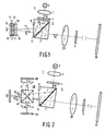
- reference numeral 1 denotes an illumination system comprising a radiation source 2, for example a metal-halide lamp and a condensor system 3 which is schematically indicated by a single lens, although this system may include a plurality of lenses and/or mirrors.
- the illumination system produces a beam b1 which is incident on image display panel 10.
- This panel is, for example, a liquid crystal panel (or LCD).
- Such a panel comprises a layer of liquid crystalline material 13, for example of the nematic type, which is enclosed between two plates 11 and 12.
- the plate 11 is transparent and, for example, made of glass, whilst the plate 12 may optionally be also transparent or reflecting.
- Each of the plates is provided with a control electrode 14, 15, the electrode 14 being transparent whereas the electrode 15, when a glass plate 12 is used, is reflective and, when a reflecting plate 12 is used, may be transparent.
- the electrodes can be divided into a large number of rows and columns, thus defining a large number of image elements in the display panel.
- the different image elements can then be controlled by driving the matrix electrodes, as is shown schematically by means of the drive terminals 16 and 17. Thus, an electric field can be applied at the desired position across the liquid crystalline material 13.
- Such an electric field causes a change of the effective refractive index of the material 13, so that the light passing through a given image element is submitted or not submitted to a rotation of the polarization direction, depending on whether a local electric field is present or not present in the region of the relevant image element.
- an actively controlled panel may alternatively be used.
- one of the substrate plates is provided with an electrode whilst the other plate is provided with the semi-conductor drive electronics.
- Each of the image elements is now driven by its own active control element such as, for example, a thin film transistor.
- the image display panel may alternatively be part of a more complex system such as the one described in US-A-4,127,322.
- a cathode-ray tube In said system an image is generated with the aid of a cathode-ray tube.
- the light beam emanating from this tube is incident on a photo-conductive layer in which a charge pattern is produced in accordance with the image on the cathode-ray tube.
- This causes an electric field to be formed across a layer of liquid crystalline material present between the photo-conductive layer and a second, counter, electrode, also in accordance with the image on the cathode-ray tube.
- the varying electric field causes a variation of the double refraction in the liquid crystalline layer and consequently, within a projection beam incident on this layer, local differences in the rotation of the polarization direction.
- this system must be provided with a number of additional layers.
- the arrangement disclosed in US-A-4,127,322 is intended for more professional applications.
- the beam incident on this panel must be polarized, preferably be linearly polarized.
- the radiation source 2 generally radiates non-polarized light.
- a polarizer 4 a linearly polarized component having the desired polarization direction is selected from this light.
- a polarization analyser 9 is provided the polarization direction of which is, for example, effectively parallel to the polarization direction of the polarizer 4. This causes the light originating from the image elements of the display panel which are energized and do not change the polarization direction of the beam to be transmitted by the analyser to a projection lens system 20.
- the light originating from non-energized image elements which rotate the polarization direction of the beam through 90° is blocked by the analyser.
- the analyser 9 converts the polarization modulation of the beam into an intensity modulation.
- the projection lens system 20 which is shown schematically with one single lens element displays the display panel 10 on a projection screen 30.
- the optical path length between this screen and the lens system 20 is relatively long. So as to limit the dimensions of the arrangement, the radiation path between the projection system 20 and the screen 30 can be folded with the aid of reflectors.
- the image elements across which no electric field is applied are displayed as black dots on the projection screen 30. It is alternatively possible to so control an image element, that is to say to apply such a field strength across it, that of the incident linearly polarized light the polarization direction is not rotated through 90° but that this linearly polarized light is converted into elliptically polarized light. A portion of this light is transmitted to the projection screen and the remaining portion is blocked. The relevant image element is then not displayed on the projection screen as a black or as a white element but as a grey element, the grey scale being adjustable.
- an image projection arrangement having liquid crystal display panels can in principle also be operated with circularly or elliptically polarized light.
- the image display panel can then slightly change the direction of rotation of the circularly polarized light or the ratio between the elliptical axes of the elliptically polarized light.
- additional polarization means the light must ultimately be converted into linearly polarized light and said changes be converted into changes of the polarization direction of this linearly polarized light.
- an extra layer of liquid crystalline material which rotates the polarization direction of the full beam through 90° can be applied in series with the image display panel 10, so that the image on the projection screen has the same polarity as the image formed in an arrangement having an image display panel whose image elements do not change the polarization direction in the driven state.
- An additional polarization rotator which in Fig. 1 is denoted by reference numeral 18, can also be used if in an arrangement in which the image elements in the driven state do not change the polarization direction one yet wants to have these image elements appear as black elements on the projection screen, for example with the object of obtaining an increased contrast or to effect a decrease of the colour dependency of the arrangement, or to increase the switching rate of the display panel.
- ⁇ /4-plate wherein ⁇ is the wavelength of the projection light
- This polarization rotator can also be applied in the embodiments still to be described.
- Fig. 1 shows only the chief rays of the beams b1 and b2. These beams have however a given width such that they cover the entire image display panel 10.
- the projection lens system 20 may only catch light from the beam b2 and no light from the beam b1.
- an angle-dependent beam separator in the form of a composite prism system 5.
- This system comprises two transparent prisms 6 and 7 of glass or a synthetic resin material between which there is an air layer 8.
- the critical angle ⁇ g the critical angle
- the index of refraction of the prisms 6 and 7 and the orientation of the air layer 8 have been chosen such that the beam b1 originating from the light source, is reflected in its totality by the interface 6, 8 towards the display panel 10 and the bundle b2 originating from this panel is fully transmitted by this interface.
- the angle of incidence of the beam b1 and the beam b2, respectively, on the interface is therefore larger or smaller, respectively, than the critical angle.
- the prism system effects that the chief ray of the beam b2 encloses a wide angle, which may be near 90°, with the chief ray of the beam b1. Consequently, the projection lens system 20 can be positioned near the display panel 10, so that the length of the image projection arrangement can be considerably less than in the absence of the prism system.
- a colour image is to be projected, it is possible to use instead of an image display system having one image display panel a composite image display system which comprises, for example, three image display panels and a plurality of colour-selective beam splitters.
- Fig. 2 shows an embodiment of such a composite image display system.
- the colour splitting is effected by what is commonly referred to as a dichroic cross 40 formed by two dichroic mirrors 41 and 42.
- the beam b1 reflected by the interface 6, 8 is incident on the first dichroic mirror 41 which reflects, for example, blue light.
- the blue component b 1,b is incident on the display panel 50 in which the blue sub-image is generated and the beam b 2,b modulated with the blue image information is reflected to the dichroic cross 40 by the panel 50.
- the beam having a red and a green component and transmitted by the dichroic mirror 41 is incident on the second dichroic mirror 42 which reflects the red component b 1,r to the display panel 60. In this panel the red sub-image is generated.
- the beam b 2,r modulated with the red image information is reflected to the dichroic cross 40.
- the beam component b 1,g transmitted by the mirror 42 is modulated by the green image display panel 10 and reflected as the beam component b 2,g to the dichroic cross 40. Since the dichroic mirrors 41 and 42 again reflect the returning beam component b 2,b and b 2,r and transmit the beam component b 2,g , these beam components are combined in one beam b2 which is modulated with the colour image information.
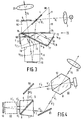
- Fig. 3 shows a further embodiment of a colour image projection arrangement in which the layer of air at which the total reflection of the beam b1 originating from the source occurs is not enclosed between two prisms.
- This embodiment comprises a prism system 70 by means of which both the beam separation and the colour splitting and colour recombination are effected.
- the system 70 is formed from three prisms 71, 72 and 73, a first air layer 75 being present between the prisms 71 and 72 and an air layer 76 being present between the prisms 72 and 73.
- the prism 72 is coated with a first dichroic layer 77 and the prism 73 with a second dichroic layer 78.
- the beam b1 originating from the source 2 enters the prism 71 via the plane 81 and is thereafter incident on the plane 80 which is an interface between the prism material, for example glass, and air.
- the angle of incidence ⁇ i exceeds the critical angle so that the beam b1 is totally reflected.
- This beam passes the layer of air 75 since the angle of incidence on the interface of the prism material 72 to air is less than the critical angle.
- the beam b1 is incident on the dichroic layer 77 which reflects, for example, the blue component b 1,b .
- This beam component is incident at an angle larger than the critical angle onto the interface between the prism 72 and the layer of air 75 and is totally reflected to the blue display panel 50.
- the beam component b 2,b modulated with the blue image information is totally reflected from the layer of air 75 to the dichroic layer 77 which reflects this beam component towards the projection lens system 20.
- the beam having the colour composition red and green which is transmitted by the dichroic layer 77 is incident on the second dichroic layer 78 which reflects the red component b 1,r and transmits the green component b 1,g towards the green image display panel 10.
- the beam component b 2,g modulated with the green image information is directly reflected to the projection lens system 20.
- the red beam component b 1,r reflected by the dichroic layer 78 is totally reflected from the layer of air 76 to the red image display panel 60.
- the beam component b 2,r modulated with the red image information is first totally reflected from the layer of air 76 and is thereafter reflected by the dichroic layer 78 and combined with the green beam component b 2,g .
- these beam components are combined with the blue beam component b 2,b and the complete beam b2 is obtained which is modulated with the colour image information.
- This beam is incident on the interface 80 between the prism 71 and air at an angle less than the critical angle and is transmitted to the projection lens system 20.
- the polarizer 4 and the analyser 9 are provided on the face 80 of the prism 71, so that these elements act simultaneously on the three colour components and there is no need for a separate system of such elements for each colour component, and in addition no separate carriers for the elements 4 and 9 are necessary.
- a prism element 82 is preferably disposed on the face 80 of the prism 71. It can be ensured that the plane of incidence 81 or the exit plane 83, respectively, of the prism system has an equal orientation relative to the chief ray of the first and second beam, respectively, as an image display panel. As regards the projection beam b1, b2 the prism system 70 then behaves as a double plane-parallel plate, as a result of which the optical aberrations of the projection beam can be minimized in a simple manner.
- Fig. 4 illustrates an embodiment of the image projection arrangement in which a very efficient use is made of the light coming from the illumination system 1.
- the beam b1 produced by the source comprises two beam components b′1 and b ⁇ 1 with mutually perpendicular directions of polarization.
- the beam b1 is incident on a polarization-sensitive beam splitter 90.
- This beam splitter may be formed from two transparent prisms 91 and 92 between which a polarization-separating layer 93 is provided.
- the layer 93 reflects the beam component b′1 whose polarization direction is parallel to the plane of incidence, and which is commonly denoted as the p-component, and transmits the component b ⁇ 1 whose polarization direction extends transversely of the plane of incidence, and which is commonly referred to as the s-component.
- the plane of incidence is the plane formed by the chief ray of the incident beam and the normal to plane 93.
- the beam component b′1 reflected by the layer 93 is directed to the image display panel 10 by a reflector 95.
- This component passes through the air layer 8 of the angle-dependent beam separator 5 because its angle of incidence is less than the critical angle.
- the beam component b′2 which is modulated with the image information and is reflected is incident at an angle larger than the critical angle on the air layer 8 and is totally reflected to a reflector 96 which reflects the component b′2 to the polarization-sensitive beam splitter 90.
- the light coming from the energized image elements of the panel 10, which do not change the polarization direction is reflected to the projection lens system 20 by the layer 93.
- the light coming from the non-energized image elements is transmitted by the layer 93 to the illumination system 1.
- the s-polarized beam component b ⁇ 1 is reflected by the reflector 96 to the beam splitter 5, is subjected there to a total reflection to the image display panel 10, is there modulated with the image information and is reflected, thereafter passes through the beam splitter 5 and is finally reflected by the reflector 95 to the polarization-sensitive beam splitter 90.
- this beam component b ⁇ 2 those portions which originate from the energized image elements are transmitted to the projection lens system.
- the beam splitter 90 does not only provide that two beam components b′1 and b ⁇ 1 are formed, but also that these components after having been modulated by the image display panel are combined again to one beam b2.
- the polarization-sensitive beam splitter 90 provides that the polarization modulation of the beam components is converted into an intensity variation of these components. Consequently, this beam splitter also replaces a polarizer and an analyser which otherwise have to be provided before and behind, respectively, the image display panel. Because of the diverse functions of the beam splitter 90 the number of elements in the embodiment of Fig. 4 can be limited to a minimum.
- Fig. 4 may alternatively be provided with a composite image display system in a similar manner as described with reference to Fig. 2.
- the dichroic cross 40 of last-mentioned Figure is schematically represented in Fig. 4 by reference numeral 40.
- the colour split can also here be effected by means of what is commonly referred to as a colour-splitting prism system.
- Fig. 5 shows how such a system 100 can be arranged in the colour image projection arrangement with reflecting image display panels 10, 50 and 60 for generating the green, blue and red sub-image, respectively.
- the prism system 100 is formed by three prisms 101, 102 and 103, a first dichroic layer 104 being provided on the interface between the prisms 101 and 102 and a second dichroic layer 105 being provided on the interface between the prisms 102 and 103.
- the dichroic layer 104 reflects the blue beam component b′ 1,b to the front face of the prism 101, which borders on air, at such an angle that this beam component is reflected to the blue display panel 50.
- the green component b′ 1,g is transmitted to the green image display panel 10 whilst the red component b′ 1,r is reflected to the front side of the prism 102.
- a layer of air 106 is present between this front side and the dichroic layer 104.
- the sub-beam component b′ 1,r is incident on the glass-to-air interface at such an angle that this component is reflected to the red display panel 60.
- the components b′ 2,b ; b′ 2,g and b′ 2,r after having been modulated by the associated display panels 50, 10 and 60, are recombined by the same system 100 to a sub-beam b′2.
- the polarization-sensitive beam splitting prism 90 converts the polarization modulation of this sub-beam into an intensity modulation.
- the beam b ⁇ 1, not shown in Fig. 5, travels through the same path as the sub-beam b′1 but in the opposite direction.
- a polarization-sensitive beam splitter in the image projection arrangement can be constituted in known manner by a Wollaston prism consisting of two cemented-together prisms of double-refractive material, the optical axis of the two prisms being perpendicular to each other. It is alternatively possible to utilize a what is commonly denoted as a Glan-Thompson prism or a Glan-Taylor prism of double-refractive material, in which one beam component having one of the polarization directions, p or s, is subjected to total internal reflection at a prism face and the other component is not subjected to such an internal reflection.
- the two last-mentioned prisms as well as the Wollaston prism are expensive because of the double-refractive material to be used for them.
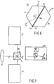
- This beam splitter 110 is formed by two transparent prisms 111 and 112 of, for example, glass, with an intermediate layer 113.
- This layer is formed by a double-refractive material, preferably a liquid crystalline material which may evidence a high double reflection.
- the ordinary index of refraction n o of the liquid crystalline material is substantially always equal to approximately 1.5, whilst the extraordinary index of refraction n e can have a value between 1.6 and 1.8 depending on the composition of the layer 113.
- the prisms 111 and 112 are provided with what are commonly referred to as orientation layers 114 and 115 which ensure that the optical axis of the layer 113 is perpendicular to the plane of drawing. In Fig. 6 this axis is indicated by the circle 116.
- the beam b1 incident on the beam splitter has two polarization components, the p- and s-polarized components. Measures have been taken to ensure that the refractive index of the prism material is equal to n e of the layer 113, for example 1.8. If the beam b1 is incident on the layer 103 at an angle of incidence ⁇ i which exceeds or is equal to the critical angle ⁇ g the p-polarized beam component is subjected to a total reflection in the direction of the arrow 117 as the ordinary index of refraction applies to this component.
- the extraordinary refractive index of the liquid crystalline material applies, so that this component does not "see” any refractive index difference on passing through the beam splitter, and consequently passes through the layer 113 and the prism 112 in the original direction.
- the beam splitter 110 made of such a material is suitable for a large range of angles of incidence.
- the refractive index of the prism material and that of the layer 113 vary in the same way with varying wavelength of the beam b1, so that the beam splitter has a high polarization efficiency over a large wavelength range.
- a very important advantage of the beam splitter of Fig. 6 is that it is cheap since no expensive double-refractive prism material need to be used and its production is relatively simple.
- the prisms 111 and 112 there is no need for the prisms 111 and 112 to be solid, it is alternatively possible for these prisms to consist of glass, or other transparent, walls in which a transparent liquid or synthetic material having a high refractive index, equal to n e of the layer 113 is applied. These walls must have the same refractive index as the liquid or synthetic resin material which shall not evidence any depolarizing effects.
- the beam splitter 110 can also be used for combining the sub-beams b′1 and b ⁇ 2 after they have been modulated with image information by the reflecting image display panels.
- Fig. 7 shows schematically and in a plan view a colour image projection arrangement having three colour channels 120, 121 and 122 for the respective primary colours green, blue and red.
- Each of these colour channels comprises a separate radiation source, an angle-dependent beam splitter and a reflective image display panel. These elements 2, 5 and 10 are shown in the green channel. For the other channels the corresponding elements are arranged in a similar manner.
- the differently coloured beams b g , b b and b r modulated with the image information are combined by a dichroic cross 40 or a colour-combining prism system to one beam b which is projected on a display screen, not shown, by the projection lens system.
- Each of the colour channels 120, 121, 122 of the arrangement shown in Fig. 7 can alternatively be provided, similar to Fig. 4, with a polarization-sensitive beam splitter so that two mutually perpendicularly polarized beams are formed which are modulated by the same image display panel and are thereafter recombined, so that an optimum use of the available light is made.
- a directly controlled reflective LCD display panel which can be used in the arrangement according to the invention is disclosed in US-A-4,239,346.
- the inventive idea is also suitable for use in a colour image projection device in which only one display panel is used.
- This arrangement may be of a structure as shown in the Figs. 1 and 4, in which the monochrome panel 10 is replaced by a composite or colour panel.
- This colour panel then comprises a number of image elements which is, for example, three times as large as the number of image elements of a monochrome panel.
- the image elements of the colour panel are arranged in three groups, a red, green and blue sub-image being generated by these groups. An image element of each of the groups is always added to an image element on the projection screen.
- Each of the image elements is then, for example, preceded by an individual colour filter which only transmits the colour desired for the relevant image element.
Landscapes
- Physics & Mathematics (AREA)
- General Physics & Mathematics (AREA)
- Optics & Photonics (AREA)
- Engineering & Computer Science (AREA)
- Multimedia (AREA)
- Signal Processing (AREA)
- Projection Apparatus (AREA)
- Liquid Crystal (AREA)
- Devices For Indicating Variable Information By Combining Individual Elements (AREA)
- Transforming Electric Information Into Light Information (AREA)
- Video Image Reproduction Devices For Color Tv Systems (AREA)
Claims (7)
- Bildprojektionsvorrichtung (1) mit einer Lichtquelle (2) zur Erzeugung eines ersten Lichtbündels (b₁), einem im Weg des ersten Lichtbündels (b₁) angeordneten reflektierenden Bildwiedergabesystem (10, 40) mit mindestens einem Bildwiedergabeschirm (10) zur Erzeugung, aus dem ersten Lichtbündel durch modulierte Reflexion zu einem zweiten Lichtbündel (b₂), eines zu projizierenden Bildes, und einem im Weg des zweiten Lichtbündels (b₂) angeordneten Projektionslinsensystem (20) zur Projektion des von dem Bildwiedergabesystem erzeugten Bildes auf einen Projektionsschirm (30), dadurch gekennzeichnet, daß zwischen der Lichtquelle (2) und dem Bildwiedergabesystem einerseits und zwischen diesem System und dem Projektionslinsensystem (20) andererseits ein bündeltrennender Übergang von einem ersten (6) in ein zweites Medium (8) vorgesehen ist, wobei diese Medien unterschiedliche Brechzahlen haben, der Übergang so angeordnet ist, daß eines der ersten und zweiten Lichtbündel (b₁), (b₂) an dem Übergang vollständig reflektiert wird, während das andere Lichtbündel an dem Übergang durchgelassen wird und das erste Lichtbündel auf den Bildwiedergabeschirm (10) unter einem Winkel einfällt, der bezogen auf die Normale zum Bildwiedergabeschirm größer als null ist.
- Bildprojektionsvorrichtung nach Anspruch 1, dadurch gekennzeichnet, daß der bündeltrennende Übergang von einer Grenzfläche zwischen Luft und transparentem Material gebildet wird.
- Bildprojektionsvorrichtung nach Anspruch 2, dadurch gekennzeichnet, daß der bündeltrennende Übergang in einem Prismensystem (5) enthalten ist, das aus zwei transparenten Prismen (6, 7) mit einer Luftschicht (8) zwischen zwei einander zugewandten Prismenflächen besteht.
- Bildprojektionsvorrichtung nach Anspruch 1, 2 oder 3, in der das Bildwiedergabesystem (10) die Polarisationsrichtung des zweiten Lichtbündels (b₂) der Bildinformation entsprechend moduliert, dadurch gekennzeichnet, daß in dem Strahlungsweg von der Lichtquelle (2) zum bündeltrennenden Übergang einerseits und in dem Strahlungsweg von diesem Übergang zum Projektionslinsensystem (20) andererseits ein polarisationsempfindlicher Strahlteiler (90) vorhanden ist zur Aufteilung des aus der Lichtquelle (2) stammenden Strahlenbündels (b₁) in zwei zueinander senkrecht polarisierte Teilbündel (b′₁, b˝₁), und zum Wiederzusammenführen der beiden Teilbündel (b′₂, b˝₂), nachdem sie mit Bildinformation moduliert worden sind, wobei die unmodulierten Teilbündel (b′₁, b˝₁) beide auf die gleichen Bildelemente des Bildwiedergabesystems (10) einfallen und den gleichen Einfallswinkel haben und der Strahlungsweg der Teilbündel (b′₁, b˝₂; b˝₁, b′₂) mit Reflexionsmitteln (95), (96) zum Lenken der Teilbündel zwischen dem Übergang und dem Strahlteiler (90) versehen ist, wobei die Anordnung so ist, daß jedes der zwei senkrecht zueinander polarisierten Teilbündel (b′₁, b′₂; b˝₁, b˝₂) an diesem Übergang einmal vollständig reflektiert und einmal vollständig durchgelassen wird, und daß beide Teilbündel einander überlappen.
- Bildprojektionsvorrichtung nach Anspruch 1, 2, 3 oder 4, dadurch gekennzeichnet, daß das Bildwiedergabesystem (10) ein Farbbildwiedergabesystem ist, mit einer Anzahl zwischen dem bündeitrennenden Übergang und dem genannten mindestens einen Wiedergabeschirm angeordneter farbselektiver Elemente (41, 42; 71, 72, 73) zum Aufteilen des aus der Lichtquelle (2) stammenden Lichtbündels (b₁) in drei einfarbige Teilbündel (b1,r, b1,g, b1,b) unterschiedlicher Farbe und zum Zusammenführen der mit einfarbiger Bildinformation modulierten Teilbündel (b2,r, b2,g, b2,b) zu einem einzigen mit Farbbildinformation modulierten Lichtbündel (b₂), und daß im Weg jedes der Teilbündel ein gesonderter Bildwiedergabeschirm (10, 50, 60) angeordnet ist zur Erzeugung eines Teilbildes einer bestimmten Farbe entsprechend der Farbe des auf den Wiedergabeschirm einfallenden Teilbündels.
- Bildprojektionsvorrichtung nach Anspruch 1, 2, 3 oder 4, dadurch gekennzeichnet, daß das Bildwiedergabesystem ein Farbbildwiedergabesystem ist, das einen einzelnen Bildwiedergabeschirm (10) enthält, dessen Bildelemente in Gruppen unterteilt sind, wobei jede Gruppe ein Teilbild einer bestimmten Farbe erzeugt, und daß es für jedes der Bildelemente ein farbselektives Element gibt, das nur Licht der Farbe durchläßt, die der Farbe des von der Gruppe, zu der das betreffende Bildelement gehört, zu erzeugenden Teilbildes entspricht.
- Bildprojektionsvorrichtung nach Anspruch 1, 2, 3 oder 4, zur Projektion eines Farbbildes, dadurch gekennzeichnet, daß die Lichtquelle aus einer Vielzahl von einfarbigen Lichtquellen gebildet ist, die eine entsprechende Anzahl einfarbige Lichtbündel aussenden, wobei die Lichtquellen Teil gesonderter Farbkanäle (120, 121, 122) sind, in denen jeweils ein einfarbiger reflektierender Bildwiedergabeschirm (10) und ein bündeltrennender Übergang nach einem der Ansprüche 1, 2, 3 oder 4 angeordnet sind, und daß zwischen den bündeltrennenden Übergängen und dem Projektionslinsensystem ein System aus farbselektiven Elementen (40) zum Zusammenführen der mit einfarbiger Information modulierten Lichtbündel (br, bg, bb) zu einem einzigen mit Farbbildinformation modulierten Lichtbündel (b) liegt.
Applications Claiming Priority (2)
| Application Number | Priority Date | Filing Date | Title |
|---|---|---|---|
| NL8802517 | 1988-10-13 | ||
| NL8802517A NL8802517A (nl) | 1988-10-13 | 1988-10-13 | Beeldprojektie-inrichting. |
Publications (2)
| Publication Number | Publication Date |
|---|---|
| EP0364043A1 EP0364043A1 (de) | 1990-04-18 |
| EP0364043B1 true EP0364043B1 (de) | 1995-01-04 |
Family
ID=19853045
Family Applications (1)
| Application Number | Title | Priority Date | Filing Date |
|---|---|---|---|
| EP89202545A Expired - Lifetime EP0364043B1 (de) | 1988-10-13 | 1989-10-09 | Bildprojektionsanordnung |
Country Status (8)
| Country | Link |
|---|---|
| US (1) | US4969730A (de) |
| EP (1) | EP0364043B1 (de) |
| JP (1) | JP3060049B2 (de) |
| KR (1) | KR0166577B1 (de) |
| CN (1) | CN1020962C (de) |
| DE (1) | DE68920396T2 (de) |
| HK (1) | HK144196A (de) |
| NL (1) | NL8802517A (de) |
Families Citing this family (111)
| Publication number | Priority date | Publication date | Assignee | Title |
|---|---|---|---|---|
| JPH0274903A (ja) * | 1988-09-12 | 1990-03-14 | Seiko Epson Corp | ダイクロイック光学素子及び投射型表示装置 |
| US5108172A (en) * | 1989-08-11 | 1992-04-28 | Raf Electronics Corp. | Active matrix reflective image plane module and projection system |
| AU6175190A (en) | 1989-08-11 | 1991-03-11 | Raf Electronics Corp. | Wafer based active matrix |
| US5024524A (en) * | 1989-08-11 | 1991-06-18 | Raf Electronics Corp. | Reflective image plane module |
| JPH03121486A (ja) * | 1989-10-04 | 1991-05-23 | Pioneer Electron Corp | 投射型表示装置 |
| US5185660A (en) * | 1989-11-01 | 1993-02-09 | Aura Systems, Inc. | Actuated mirror optical intensity modulation |
| JP2942344B2 (ja) * | 1989-11-22 | 1999-08-30 | 旭光学工業株式会社 | プロジェクター |
| KR930003307B1 (ko) * | 1989-12-14 | 1993-04-24 | 주식회사 금성사 | 입체용 프로젝터 |
| DE69028497T2 (de) * | 1989-12-20 | 1997-02-06 | Canon Kk | Polarisierendes Beleuchtungsgerät |
| JPH0643827Y2 (ja) * | 1990-01-18 | 1994-11-14 | 矢崎総業株式会社 | 表示装置 |
| JP2915467B2 (ja) * | 1990-02-22 | 1999-07-05 | キヤノン株式会社 | 液晶プロジェクタ |
| USRE36740E (en) * | 1990-03-30 | 2000-06-20 | Nikon Corporation | Cata-dioptric reduction projection optical system |
| US5220454A (en) * | 1990-03-30 | 1993-06-15 | Nikon Corporation | Cata-dioptric reduction projection optical system |
| JPH03288124A (ja) * | 1990-04-04 | 1991-12-18 | Victor Co Of Japan Ltd | カラー画像表示装置の光学系 |
| US5237442A (en) * | 1990-06-12 | 1993-08-17 | U.S. Philips Corp. | Device for optical heterodyne detection and mirror system suitable for use in such a device |
| JP2575558Y2 (ja) * | 1990-12-26 | 1998-07-02 | エルジー電子株式会社 | 液晶投写形ディスプレイの光学系構造 |
| US5206673A (en) * | 1991-02-22 | 1993-04-27 | Japan Aviation Electronics Industry Limited | Reflection type overhead projector |
| KR930005545B1 (ko) * | 1991-04-16 | 1993-06-23 | 주식회사 금성사 | 피디엘씨 이미지모듈을 이용한 프로젝션 광학계 |
| JP3015201B2 (ja) * | 1992-05-06 | 2000-03-06 | キヤノン株式会社 | 画像形成装置、投射型表示装置並びに光変調装置 |
| JP3076678B2 (ja) * | 1992-08-21 | 2000-08-14 | 松下電器産業株式会社 | 投写形画像表示装置 |
| US5420655A (en) * | 1992-12-16 | 1995-05-30 | North American Philips Corporation | Color projection system employing reflective display devices and prism illuminators |
| US5402184A (en) * | 1993-03-02 | 1995-03-28 | North American Philips Corporation | Projection system having image oscillation |
| JP3168765B2 (ja) * | 1993-04-01 | 2001-05-21 | 松下電器産業株式会社 | 偏光装置および該偏光装置を用いた投写型表示装置 |
| US5552922A (en) * | 1993-04-12 | 1996-09-03 | Corning Incorporated | Optical system for projection display |
| US5309188A (en) * | 1993-05-21 | 1994-05-03 | David Sarnoff Research Center, Inc. | Coupling prism assembly and projection system using the same |
| US5386250A (en) * | 1993-08-09 | 1995-01-31 | Philips Electronics North America Corp. | Two-source illumination system |
| US5448407A (en) * | 1993-09-03 | 1995-09-05 | Industrial Technology Research Institute | Equivalent wollaston prism for an optical pick-up head and an optical pick-up head using of the same |
| WO1995030927A1 (en) * | 1994-05-06 | 1995-11-16 | Philips Electronics N.V. | Beam-combining device and colour image projection apparatus provided with such a device |
| CN1089447C (zh) * | 1994-05-06 | 2002-08-21 | 皇家菲利浦电子有限公司 | 光束合成装置和装有该装置的彩色图象投影设备 |
| US5640214A (en) * | 1994-09-30 | 1997-06-17 | Texas Instruments Incorporated | Printer and display systems with bidirectional light collection structures |
| US5579134A (en) * | 1994-11-30 | 1996-11-26 | Honeywell Inc. | Prismatic refracting optical array for liquid flat panel crystal display backlight |
| US5644323A (en) * | 1994-12-21 | 1997-07-01 | Siliscape, Inc. | Miniature synthesized virtual image electronic display |
| US5684497A (en) * | 1994-12-21 | 1997-11-04 | Siliscape, Inc. | Twice folded compound magnified virtual image electronic display |
| EP0722253A3 (de) * | 1995-01-10 | 1996-10-30 | Ibm | Anordnungen für Projektionsanzeigen mit Lichtventilen in Reflexion |
| US5612753A (en) * | 1995-01-27 | 1997-03-18 | Texas Instruments Incorporated | Full-color projection display system using two light modulators |
| US5596451A (en) * | 1995-01-30 | 1997-01-21 | Displaytech, Inc. | Miniature image generator including optics arrangement |
| US6227670B1 (en) | 1995-03-06 | 2001-05-08 | Nikon Corporation | Projection type display apparatus |
| EP0734184B1 (de) * | 1995-03-23 | 2001-01-17 | International Business Machines Corporation | Wirksames optisches System für eine hochauflösende Projektionsanzeige mit Reflexionslichtventilen |
| EP0824829B1 (de) | 1995-05-11 | 2003-02-12 | Digital Projection Limited | Projektionsvorrichtung |
| US5621486A (en) * | 1995-06-22 | 1997-04-15 | International Business Machines Corporation | Efficient optical system for a high resolution projection display employing reflection light valves |
| US5995284A (en) * | 1996-03-29 | 1999-11-30 | 3M Innovative Properties Company | Polarized illumination system for LCD projector |
| US6082863A (en) * | 1996-08-16 | 2000-07-04 | Raychem Corporation | Color projection prism |
| JP3557317B2 (ja) * | 1996-09-02 | 2004-08-25 | テキサス インスツルメンツ インコーポレイテツド | プロジエクタ装置及び色分離合成装置 |
| US5829854A (en) * | 1996-09-26 | 1998-11-03 | Raychem Corporation | Angled color dispersement and recombination prism |
| JP2939237B2 (ja) * | 1997-04-09 | 1999-08-25 | 三星電子株式会社 | 反射型プロジェクター |
| JP3444521B2 (ja) * | 1997-06-20 | 2003-09-08 | シャープ株式会社 | 投影型画像表示装置 |
| US5951135A (en) * | 1997-10-14 | 1999-09-14 | Raychem Corporation | Color image projection system |
| US6219186B1 (en) | 1998-04-06 | 2001-04-17 | Optimize Incorporated | Compact biocular viewing system for an electronic display |
| US5926318A (en) * | 1998-04-06 | 1999-07-20 | Optimize Incorporated | Biocular viewing system with intermediate image planes for an electronic display device |
| CA2339545A1 (en) | 1998-06-08 | 1999-12-16 | Karlheinz Strobl | Efficient light engine systems, components and methods of manufacture |
| JP2000199883A (ja) * | 1998-10-29 | 2000-07-18 | Fujitsu Ltd | 反射型プロジェクタ装置 |
| US6295173B1 (en) | 1998-12-18 | 2001-09-25 | Unaxis Balzers Aktiengesellschaft | Configuration for color division and/our recombination |
| US6561652B1 (en) | 1998-12-22 | 2003-05-13 | Vanntelligent (Bvi) Limited | Optical assembly for reflective light valves |
| JP3714003B2 (ja) | 1999-03-02 | 2005-11-09 | セイコーエプソン株式会社 | 投写型表示装置及びこれに用いられるプリズム |
| US6550919B1 (en) * | 1999-03-26 | 2003-04-22 | Unaxis Balzers Aktiengesellschaft | Spectral light division and recombination configuration as well as process for the spectrally selective modulation of light |
| US6185047B1 (en) | 1999-05-17 | 2001-02-06 | Infocus Corporation | Image projection system packaged to operate lying flat with a very low profile |
| US6560048B1 (en) | 1999-09-30 | 2003-05-06 | Mitsubishi Denki Kabushiki Kaisha | Prism having two inner surfaces and outer shape regarded as plane parallel plate |
| US6398364B1 (en) * | 1999-10-06 | 2002-06-04 | Optical Coating Laboratory, Inc. | Off-axis image projection display system |
| JP3727543B2 (ja) * | 2000-05-10 | 2005-12-14 | 三菱電機株式会社 | 画像表示装置 |
| US6542307B2 (en) * | 2000-10-20 | 2003-04-01 | Three-Five Systems, Inc. | Compact near-eye illumination system |
| US7324279B2 (en) * | 2000-12-28 | 2008-01-29 | Texas Instruments Incorporated | Dual modulator projection system |
| KR100397428B1 (ko) * | 2000-12-29 | 2003-09-13 | 엘지전자 주식회사 | 전반사 프리즘 및 이를 이용한 화상 투사장치 |
| US7145704B1 (en) | 2003-11-25 | 2006-12-05 | Cheetah Omni, Llc | Optical logic gate based optical router |
| US7339714B1 (en) | 2001-02-02 | 2008-03-04 | Cheetah Omni, Llc | Variable blazed grating based signal processing |
| US6793344B2 (en) | 2001-06-26 | 2004-09-21 | Integrated Microdisplays Limited | Optical systems for liquid crystal display projectors |
| US6863401B2 (en) * | 2001-06-30 | 2005-03-08 | Texas Instruments Incorporated | Illumination system |
| US7222967B2 (en) * | 2001-08-10 | 2007-05-29 | Canon Kabushiki Kaisha | Image display optical system and projection type image display apparatus |
| US7207678B2 (en) * | 2001-12-31 | 2007-04-24 | Texas Instruments Incorporated | Prism for high contrast projection |
| US7034811B2 (en) | 2002-08-07 | 2006-04-25 | Hewlett-Packard Development Company, L.P. | Image display system and method |
| US7172288B2 (en) | 2003-07-31 | 2007-02-06 | Hewlett-Packard Development Company, L.P. | Display device including a spatial light modulator with plural image regions |
| US7390092B2 (en) * | 2002-11-08 | 2008-06-24 | Belliveau Richard S | Image projection lighting devices with visible and infrared imaging |
| WO2004106980A2 (en) * | 2003-05-21 | 2004-12-09 | Jds Uniphase Corporation | System and method for providing a uniform source of light |
| JP3757221B2 (ja) | 2003-08-14 | 2006-03-22 | Necビューテクノロジー株式会社 | 投写型表示装置 |
| CN100385287C (zh) * | 2003-09-03 | 2008-04-30 | 浙江舜宇光学有限公司 | 离轴式光学投影仪 |
| US20090207164A1 (en) * | 2003-11-01 | 2009-08-20 | Naoya Sugimoto | Mirror control within time slot for SLM |
| US7733558B2 (en) * | 2003-11-01 | 2010-06-08 | Silicon Quest Kabushiki-Kaisha | Display device with an addressable movable electrode |
| US8228595B2 (en) * | 2003-11-01 | 2012-07-24 | Silicon Quest Kabushiki-Kaisha | Sequence and timing control of writing and rewriting pixel memories with substantially lower data rate |
| US20090195858A1 (en) * | 2003-11-01 | 2009-08-06 | Naoya Sugimoto | Changing an electrode function |
| US7969395B2 (en) | 2003-11-01 | 2011-06-28 | Silicon Quest Kabushiki-Kaisha | Spatial light modulator and mirror device |
| US8179591B2 (en) * | 2003-11-01 | 2012-05-15 | Silicon Quest Kabushiki-Kaisha | Spatial light modulator and mirror array device |
| US20080074621A1 (en) * | 2006-08-23 | 2008-03-27 | Hirotoshi Ichikawa | Micro-mirror device with selectable rotational axis |
| US20090207324A1 (en) * | 2003-11-01 | 2009-08-20 | Naoya Sugimoto | Circuit for SLM's pixel |
| US7957050B2 (en) | 2003-11-01 | 2011-06-07 | Silicon Quest Kabushiki-Kaisha | Mirror device comprising layered electrode |
| US8081371B2 (en) * | 2003-11-01 | 2011-12-20 | Silicon Quest Kabushiki-Kaisha | Spatial light modulator and display apparatus |
| US8154474B2 (en) * | 2003-11-01 | 2012-04-10 | Silicon Quest Kabushiki Kaisha | Driving method of memory access |
| US20090103054A1 (en) * | 2003-11-01 | 2009-04-23 | Hirotoshi Ichikawa | Projection apparatus comprising spatial light modulator |
| US7973994B2 (en) * | 2003-11-01 | 2011-07-05 | Silicon Quest Kabushiki-Kaisha | Spatial light modulator |
| US20090207325A1 (en) * | 2003-11-01 | 2009-08-20 | Naoya Sugimoto | Algorithm for SLM of single hinge type |
| US20090180038A1 (en) * | 2003-11-01 | 2009-07-16 | Naoya Sugimoto | Mirror control within time slot for SLM |
| US6906852B1 (en) | 2003-12-31 | 2005-06-14 | Texas Instruments Incorporated | Wavelength discriminated image dithering |
| US7086736B2 (en) | 2004-01-20 | 2006-08-08 | Hewlett-Packard Development Company, L.P. | Display system with sequential color and wobble device |
| WO2005096098A2 (en) * | 2004-03-30 | 2005-10-13 | Carl Zeiss Smt Ag | Projection objective, projection exposure apparatus and reflective reticle for microlithography |
| US6992830B1 (en) | 2004-04-22 | 2006-01-31 | Raytheon Company | Projection display having an angle-selective coating for enhanced image contrast, and method for enhancing image contrast |
| US7023449B2 (en) | 2004-04-30 | 2006-04-04 | Hewlett-Packard Development Company, L.P. | Displaying least significant color image bit-planes in less than all image sub-frame locations |
| US20060139730A1 (en) * | 2004-12-23 | 2006-06-29 | Oehler Peter R | Illumination system with compact turning prism and projection system using same |
| US7598483B2 (en) * | 2005-02-02 | 2009-10-06 | Panasonic Corporation | Optical element and optical measurement device using the optical element |
| CN100559065C (zh) * | 2005-02-07 | 2009-11-11 | 徐佳义 | 透明照明模块 |
| US8725138B2 (en) * | 2005-03-30 | 2014-05-13 | Alcatel Lucent | Methods for network selection and discovery of service information in public wireless hotspots |
| CN100464209C (zh) * | 2005-10-26 | 2009-02-25 | 中华映管股份有限公司 | 投影装置 |
| CN100445801C (zh) * | 2006-01-18 | 2008-12-24 | 台达电子工业股份有限公司 | 用于光学设备的光线耦合装置 |
| US20090103053A1 (en) * | 2007-10-02 | 2009-04-23 | Hirotoshi Ichikawa | Projection apparatus comprising spatial light modulator |
| US7848005B2 (en) * | 2007-11-16 | 2010-12-07 | Silicon Quest Kabushiki-Kaisha | Spatial light modulator implemented with a mirror array device |
| US7876492B2 (en) * | 2007-11-16 | 2011-01-25 | Silicon Quest Kabushiki-Kaisha | Spatial light modulator and mirror array device |
| US20090128887A1 (en) * | 2007-11-16 | 2009-05-21 | Naoya Sugimoto | Spatial light modulator and mirror array device |
| US20090128462A1 (en) * | 2007-11-16 | 2009-05-21 | Naoya Sugimoto | Spatial light modulator and mirror device |
| US20090128464A1 (en) * | 2007-11-16 | 2009-05-21 | Naoya Sugimoto | Mirror array device |
| US8462355B2 (en) * | 2008-01-17 | 2013-06-11 | The Salk Institute For Biological Studies | 3D scanning acousto-optic microscope |
| JP2011526377A (ja) * | 2008-06-27 | 2011-10-06 | パナビジョン・フェデラル・システムズ・リミテッド・ライアビリティ・カンパニー | 波長分離ビームスプリッタ |
| DE102011102132A1 (de) * | 2011-05-19 | 2012-11-22 | blnsight3D GmbH | Mehrkanalanzeige mit MOEMS und Verfahren der Superposition nicht-normal abgestrahlter Bildstrahlen in Mehrkanalanzeigen mit MOEMS |
| US10230928B2 (en) | 2014-10-27 | 2019-03-12 | Texas Instruments Incorporated | Color recapture using polarization recovery in a color-field sequential display system |
| DE102015101847B4 (de) * | 2015-02-10 | 2017-11-02 | Eyesense Gmbh | Strahlteiler und Anordnung zur Untersuchung einer mittels elektromagnetischer Strahlung anregbaren Probe |
Family Cites Families (16)
| Publication number | Priority date | Publication date | Assignee | Title |
|---|---|---|---|---|
| GB1330836A (en) * | 1969-11-24 | 1973-09-19 | Vickers Ltd | Optical field-flattening devices |
| US3659918A (en) * | 1970-03-24 | 1972-05-02 | Philips Corp | Color separating prism system |
| US3893758A (en) * | 1973-04-20 | 1975-07-08 | Philips Corp | Device for projecting pictures on a screen |
| GB1474699A (en) * | 1973-12-11 | 1977-05-25 | Rank Organisation Ltd | Beam splitting prism assembly |
| NL7511838A (nl) * | 1975-10-09 | 1977-04-13 | Philips Nv | Kleurscheidende prismacombinatie. |
| US4127322A (en) * | 1975-12-05 | 1978-11-28 | Hughes Aircraft Company | High brightness full color image light valve projection system |
| DE2827573C2 (de) * | 1978-06-23 | 1983-02-03 | Blaupunkt-Werke Gmbh, 3200 Hildesheim | Großflächige Lichtquelle |
| DE3013498A1 (de) * | 1979-04-09 | 1980-10-30 | Crosfield Business Mach | Optischer modulator sowie laser-graviervorrichtung mit einem derartigen modulator |
| US4500172A (en) * | 1981-12-28 | 1985-02-19 | Hughes Aircraft Company | Two color liquid crystal light valve image projection system with single prepolarizer |
| EP0083440B1 (de) * | 1981-12-28 | 1987-08-19 | Hughes Aircraft Company | System für zweifarbige Bildprojektion durch Lichtventile aus flüssigem Kristall mit Vorpolarisation |
| JPH068934B2 (ja) * | 1982-01-11 | 1994-02-02 | オリンパス光学工業株式会社 | 光束合成装置 |
| EP0099123B1 (de) * | 1982-07-15 | 1990-11-28 | Matsushita Electric Industrial Co., Ltd. | Kopf zum optischen Aufzeichnen und Wiedergeben |
| JPS60262130A (ja) * | 1984-06-09 | 1985-12-25 | Sony Corp | 液晶表示装置 |
| US4818074A (en) * | 1986-09-03 | 1989-04-04 | Ricoh Company, Ltd. | Projection device for irradiating a light to a display device and optically magnifying and projecting a reflection light therefrom |
| JP2546206B2 (ja) * | 1987-06-15 | 1996-10-23 | 株式会社ニコン | 表面位置検出装置 |
| US4826311A (en) * | 1987-07-24 | 1989-05-02 | Hughes Aircraft Company | Prism assembly with three periscopes and projection lenses for a single light valve full-color projector |
-
1988
- 1988-10-13 NL NL8802517A patent/NL8802517A/nl not_active Application Discontinuation
-
1989
- 1989-03-22 US US07/327,288 patent/US4969730A/en not_active Expired - Lifetime
- 1989-10-09 EP EP89202545A patent/EP0364043B1/de not_active Expired - Lifetime
- 1989-10-09 DE DE68920396T patent/DE68920396T2/de not_active Expired - Lifetime
- 1989-10-10 KR KR1019890014501A patent/KR0166577B1/ko not_active Expired - Lifetime
- 1989-10-10 CN CN89107895A patent/CN1020962C/zh not_active Expired - Lifetime
- 1989-10-13 JP JP1265301A patent/JP3060049B2/ja not_active Expired - Lifetime
-
1996
- 1996-08-01 HK HK144196A patent/HK144196A/en not_active IP Right Cessation
Also Published As
| Publication number | Publication date |
|---|---|
| JP3060049B2 (ja) | 2000-07-04 |
| US4969730A (en) | 1990-11-13 |
| EP0364043A1 (de) | 1990-04-18 |
| DE68920396T2 (de) | 1995-07-27 |
| KR0166577B1 (ko) | 1999-03-20 |
| HK144196A (en) | 1996-08-09 |
| NL8802517A (nl) | 1990-05-01 |
| CN1041828A (zh) | 1990-05-02 |
| DE68920396D1 (de) | 1995-02-16 |
| KR900007043A (ko) | 1990-05-09 |
| JPH02149882A (ja) | 1990-06-08 |
| CN1020962C (zh) | 1993-05-26 |
Similar Documents
| Publication | Publication Date | Title |
|---|---|---|
| EP0364043B1 (de) | Bildprojektionsanordnung | |
| EP0313640B1 (de) | Optisches system für vollfarbige flüssigkristallichtventilbildprojektion | |
| US6398364B1 (en) | Off-axis image projection display system | |
| US6910777B2 (en) | Projector | |
| JP3480702B2 (ja) | 反射型光バルブ用投影表示システム | |
| KR100241641B1 (ko) | 이미지 투사 장치 | |
| KR100232779B1 (ko) | 투사 시스템 및 변조 시스템 | |
| US5327270A (en) | Polarizing beam splitter apparatus and light valve image projection system | |
| EP0389240B1 (de) | Polarisierender Strahlteiler und System für die Bildprojekion durch Lichtventile | |
| US5363222A (en) | Compact optical system for a single light valve full-color projector | |
| US5235444A (en) | Image projection arrangement | |
| US6089718A (en) | Projection display device | |
| WO2001073485A1 (en) | High efficiency prism assembly for image projection | |
| JPH08240797A (ja) | 反射光弁を使用したプロジェクション・ディスプレイ用光学装置 | |
| EP0361559B1 (de) | Bildprojektionsvorrichtung | |
| US5428469A (en) | Liquid crystal display projection systems employing polarizing beam splitters and passing light through display cell from both directions | |
| JP3385915B2 (ja) | 投写型画像表示装置 | |
| US4911547A (en) | Compact optical system for a single light valve projector using two axes of polarization | |
| US6819365B1 (en) | Color LCD projector with micro display light engine | |
| JPH03187696A (ja) | 投写型表示装置 | |
| JP3777836B2 (ja) | 反射型光変調素子及び投写型表示装置 | |
| JP3724216B2 (ja) | 反射型光変調素子及び投写型表示装置 | |
| JPH03241312A (ja) | 反射型液晶ライトバルブ | |
| KR19990043705A (ko) | 투사형 화상 표시 장치 | |
| KR20000044174A (ko) | 박막형 미러 어레이 패널을 포함하는 투사형 화상표시 장치 |
Legal Events
| Date | Code | Title | Description |
|---|---|---|---|
| PUAI | Public reference made under article 153(3) epc to a published international application that has entered the european phase |
Free format text: ORIGINAL CODE: 0009012 |
|
| AK | Designated contracting states |
Kind code of ref document: A1 Designated state(s): DE FR GB IT SE |
|
| 17P | Request for examination filed |
Effective date: 19901016 |
|
| 17Q | First examination report despatched |
Effective date: 19930215 |
|
| GRAA | (expected) grant |
Free format text: ORIGINAL CODE: 0009210 |
|
| AK | Designated contracting states |
Kind code of ref document: B1 Designated state(s): DE FR GB IT SE |
|
| REF | Corresponds to: |
Ref document number: 68920396 Country of ref document: DE Date of ref document: 19950216 |
|
| ITF | It: translation for a ep patent filed | ||
| ET | Fr: translation filed | ||
| PLBE | No opposition filed within time limit |
Free format text: ORIGINAL CODE: 0009261 |
|
| STAA | Information on the status of an ep patent application or granted ep patent |
Free format text: STATUS: NO OPPOSITION FILED WITHIN TIME LIMIT |
|
| 26N | No opposition filed | ||
| REG | Reference to a national code |
Ref country code: GB Ref legal event code: 711B |
|
| REG | Reference to a national code |
Ref country code: GB Ref legal event code: 727J |
|
| REG | Reference to a national code |
Ref country code: GB Ref legal event code: 711H |
|
| REG | Reference to a national code |
Ref country code: FR Ref legal event code: CD |
|
| REG | Reference to a national code |
Ref country code: GB Ref legal event code: IF02 |
|
| PGFP | Annual fee paid to national office [announced via postgrant information from national office to epo] |
Ref country code: IT Payment date: 20080924 Year of fee payment: 20 |
|
| PGFP | Annual fee paid to national office [announced via postgrant information from national office to epo] |
Ref country code: SE Payment date: 20081028 Year of fee payment: 20 |
|
| PGFP | Annual fee paid to national office [announced via postgrant information from national office to epo] |
Ref country code: FR Payment date: 20081028 Year of fee payment: 20 |
|
| PGFP | Annual fee paid to national office [announced via postgrant information from national office to epo] |
Ref country code: DE Payment date: 20081215 Year of fee payment: 20 |
|
| PGFP | Annual fee paid to national office [announced via postgrant information from national office to epo] |
Ref country code: GB Payment date: 20081211 Year of fee payment: 20 |
|
| REG | Reference to a national code |
Ref country code: GB Ref legal event code: PE20 Expiry date: 20091008 |
|
| EUG | Se: european patent has lapsed | ||
| PG25 | Lapsed in a contracting state [announced via postgrant information from national office to epo] |
Ref country code: GB Free format text: LAPSE BECAUSE OF EXPIRATION OF PROTECTION Effective date: 20091008 |
|
| REG | Reference to a national code |
Ref country code: DE Ref legal event code: R082 Ref document number: 68920396 Country of ref document: DE Representative=s name: VOLMER, GEORG, DIPL.-ING., DE |
|
| REG | Reference to a national code |
Ref country code: DE Ref legal event code: R081 Ref document number: 68920396 Country of ref document: DE Owner name: KONINKLIJKE PHILIPS N.V., NL Free format text: FORMER OWNER: KONINKLIJKE PHILIPS ELECTRONICS N.V., EINDHOVEN, NL Effective date: 20140331 Ref country code: DE Ref legal event code: R082 Ref document number: 68920396 Country of ref document: DE Representative=s name: VOLMER, GEORG, DIPL.-ING., DE Effective date: 20140331 |