EP0364054A2 - Nach dem Coriolis-Prinzip arbeitender Hochtemperatur-Massendurchflussmesser - Google Patents
Nach dem Coriolis-Prinzip arbeitender Hochtemperatur-Massendurchflussmesser Download PDFInfo
- Publication number
- EP0364054A2 EP0364054A2 EP89202571A EP89202571A EP0364054A2 EP 0364054 A2 EP0364054 A2 EP 0364054A2 EP 89202571 A EP89202571 A EP 89202571A EP 89202571 A EP89202571 A EP 89202571A EP 0364054 A2 EP0364054 A2 EP 0364054A2
- Authority
- EP
- European Patent Office
- Prior art keywords
- meter
- conductors
- flow
- high temperature
- coil
- Prior art date
- Legal status (The legal status is an assumption and is not a legal conclusion. Google has not performed a legal analysis and makes no representation as to the accuracy of the status listed.)
- Granted
Links
Images



Classifications
-
- G—PHYSICS
- G01—MEASURING; TESTING
- G01F—MEASURING VOLUME, VOLUME FLOW, MASS FLOW OR LIQUID LEVEL; METERING BY VOLUME
- G01F1/00—Measuring the volume flow or mass flow of fluid or fluent solid material wherein the fluid passes through a meter in a continuous flow
- G01F1/76—Devices for measuring mass flow of a fluid or a fluent solid material
- G01F1/78—Direct mass flowmeters
- G01F1/80—Direct mass flowmeters operating by measuring pressure, force, momentum, or frequency of a fluid flow to which a rotational movement has been imparted
- G01F1/84—Coriolis or gyroscopic mass flowmeters
- G01F1/8409—Coriolis or gyroscopic mass flowmeters constructional details
-
- G—PHYSICS
- G01—MEASURING; TESTING
- G01F—MEASURING VOLUME, VOLUME FLOW, MASS FLOW OR LIQUID LEVEL; METERING BY VOLUME
- G01F1/00—Measuring the volume flow or mass flow of fluid or fluent solid material wherein the fluid passes through a meter in a continuous flow
- G01F1/76—Devices for measuring mass flow of a fluid or a fluent solid material
- G01F1/78—Direct mass flowmeters
- G01F1/80—Direct mass flowmeters operating by measuring pressure, force, momentum, or frequency of a fluid flow to which a rotational movement has been imparted
- G01F1/84—Coriolis or gyroscopic mass flowmeters
- G01F1/8409—Coriolis or gyroscopic mass flowmeters constructional details
- G01F1/8413—Coriolis or gyroscopic mass flowmeters constructional details means for influencing the flowmeter's motional or vibrational behaviour, e.g., conduit support or fixing means, or conduit attachments
-
- G—PHYSICS
- G01—MEASURING; TESTING
- G01F—MEASURING VOLUME, VOLUME FLOW, MASS FLOW OR LIQUID LEVEL; METERING BY VOLUME
- G01F1/00—Measuring the volume flow or mass flow of fluid or fluent solid material wherein the fluid passes through a meter in a continuous flow
- G01F1/76—Devices for measuring mass flow of a fluid or a fluent solid material
- G01F1/78—Direct mass flowmeters
- G01F1/80—Direct mass flowmeters operating by measuring pressure, force, momentum, or frequency of a fluid flow to which a rotational movement has been imparted
- G01F1/84—Coriolis or gyroscopic mass flowmeters
- G01F1/8409—Coriolis or gyroscopic mass flowmeters constructional details
- G01F1/8422—Coriolis or gyroscopic mass flowmeters constructional details exciters
-
- G—PHYSICS
- G01—MEASURING; TESTING
- G01F—MEASURING VOLUME, VOLUME FLOW, MASS FLOW OR LIQUID LEVEL; METERING BY VOLUME
- G01F1/00—Measuring the volume flow or mass flow of fluid or fluent solid material wherein the fluid passes through a meter in a continuous flow
- G01F1/76—Devices for measuring mass flow of a fluid or a fluent solid material
- G01F1/78—Direct mass flowmeters
- G01F1/80—Direct mass flowmeters operating by measuring pressure, force, momentum, or frequency of a fluid flow to which a rotational movement has been imparted
- G01F1/84—Coriolis or gyroscopic mass flowmeters
- G01F1/8409—Coriolis or gyroscopic mass flowmeters constructional details
- G01F1/8427—Coriolis or gyroscopic mass flowmeters constructional details detectors
-
- G—PHYSICS
- G01—MEASURING; TESTING
- G01F—MEASURING VOLUME, VOLUME FLOW, MASS FLOW OR LIQUID LEVEL; METERING BY VOLUME
- G01F1/00—Measuring the volume flow or mass flow of fluid or fluent solid material wherein the fluid passes through a meter in a continuous flow
- G01F1/76—Devices for measuring mass flow of a fluid or a fluent solid material
- G01F1/78—Direct mass flowmeters
- G01F1/80—Direct mass flowmeters operating by measuring pressure, force, momentum, or frequency of a fluid flow to which a rotational movement has been imparted
- G01F1/84—Coriolis or gyroscopic mass flowmeters
- G01F1/845—Coriolis or gyroscopic mass flowmeters arrangements of measuring means, e.g., of measuring conduits
- G01F1/8468—Coriolis or gyroscopic mass flowmeters arrangements of measuring means, e.g., of measuring conduits vibrating measuring conduits
- G01F1/8472—Coriolis or gyroscopic mass flowmeters arrangements of measuring means, e.g., of measuring conduits vibrating measuring conduits having curved measuring conduits, i.e. whereby the measuring conduits' curved center line lies within a plane
- G01F1/8477—Coriolis or gyroscopic mass flowmeters arrangements of measuring means, e.g., of measuring conduits vibrating measuring conduits having curved measuring conduits, i.e. whereby the measuring conduits' curved center line lies within a plane with multiple measuring conduits
Definitions
- This invention relates to apparatus for a Coriolis mass flow rate meter and specifically such a meter that is suited for operation at relatively high temperatures, such as in excess of approximately 500°F (approximately 260°C).
- Coriolis mass flow rate meters are finding increasing use in many applications as an accurate way to measure the mass flow rate of various process fluids.
- a Coriolis mass flow rate meter such as that described in United States patent 4,491,025 (issued to J. E. Smith et al on January 1, 1985), contains one or two parallel conduits, each typically being a U-shaped flow conduit or tube. Each flow conduit is driven, by a magnetic drive assembly, to oscillate about an axis to create a rotational frame of reference. For a U-shaped flow conduit, this axis can be termed the bending axis. As process fluid flows through each oscillating flow conduit, movement of the fluid produces reactionary Coriolis forces that are orthogonal to both the velocity of the fluid and the angular velocity of the conduit.
- Coriolis meters known in the art, and as generally described above, utilize separate coils of wire for use within each magnetic velocity sensor and the magnetic drive assembly.
- a dual tube Coriolis meter has two magnetic velocity sensors situated in opposing positions on the sides of the two flow conduits and a single magnetic drive assembly frequently mounted to both flow conduits at respective opposing points thereon that are situated equidistant from corresponding ends of both conduits.
- each magnetic velocity sensor is typically fabricated with a sensing coil mounted to one of two flow conduits. A magnet that moves coaxially within the sensing coil is mounted to the other flow conduit.
- the drive assembly has a similar configuration to either sensing coil.
- a drive coil that forms part of the drive assembly is mounted to one of the flow conduits with a magnet, also part of the drive assembly and adapted for coaxial movement within the coil, mounted at an opposing point on the other conduit.
- a sinusoidal voltage generated by the external electronic circuit is applied, also via the wiring, to the drive coil.
- This voltage causes both the magnet and drive coil in the drive assembly to oscillate in a differential sinusoidal pattern thereby placing both flow conduits in opposing oscillatory motion about their respective bending axes.
- wiring has insulation which carries certain temperature limits.
- the insulation that is used in ordinary light gauge coil wire and/or signal wiring can not withstand temperatures as high as approximately 430°F (approximately 220°C) before the insulation becomes plastic and melts.
- 430°F approximately 220°C
- the wire used to make sensing and drive coils for use within a Coriolis meter were manufactured using such insulation, as is commonly done, then once the temperature of these coils exceeded approximately 430°F, individual turns on the coil would likely short thereby, at the very least, injecting error into the performance of the meter.
- any internal wiring which employed this insulation and ran between these coils and a suitable connector mounted on a case of the meter would also begin to melt thereby eventually permitting one or more of these wires to themselves contact the case of the meter which is generally grounded and as a result, in turn, cause the meter to malfunction.
- the wiring that runs from the sensing and drive coils is often affixed to the flow conduits by a suitable tape, varnish or adhesive.
- These three materials often carry a temperature rating of up to approximately 430°F (approximately 220°C).
- the tape, varnish, and/or adhesive would melt as the temperature of the meter exceeded 430°F thereby causing the wiring to separate from the conduits and, in turn, inject error into the operation of the meter.
- a wire coated with a high temperature ceramic insulation would be satisfactory. It may not be. Unfortunately, high temperature ceramic insulation tends to be brittle.
- ceramic insulated wire could not be affixed to an oscillating flow conduit for any appreciable amount of time without the ceramic insulation eventually fatiguing and cracking which, in turn, would cause the wire itself to disadvantageously short against a grounded flow conduit thereby injecting error into the performance of the meter.
- ceramic coated wire can not be readily wound into a small diameter coil without the insulation breaking and possibly causing shorted turns.
- the bobbins on which the sensing and drive coils are wound are frequently plastic which itself has a rather low melting point.
- the coil bobbins would increasingly deform which would, in turn, inject error into meter performance.
- An active gas cooling purge line typically using nitrogen gas flowing at a sufficient flow rate, is incorporated into the meter in order to maintain the velocity sensors and drive assembly at a relatively low temperature.
- An outer case surrounds the thermally insulated partition. Internal meter wiring is run in the space between the outer case and the thermal partition and is frequently wrapped around an internal purge tube.
- the meter disclosed in the ′143 patent provides satisfactory operation at relatively high temperatures, it quickly became apparent that this meter also suffers various drawbacks that tend to limit its utility.
- the meter is complex, relatively expensive and difficult to build.
- the meter requires that an active source of gas be connected to the purge line of the meter.
- the attendant increase in process plumbing necessitated by the purge line increases the complexity and cost of the installation of the meter, while the continual use of purge gas increases the cost associated with operating the meter.
- Third, proper operation of the meter necessitated that the cooling purge continually operate whenever the meter is at an elevated temperature.
- cooling purge fails for any reason while the meter remains at this temperature, then the coils and/or wiring would quickly fail. As such, a customer needs to exercise extreme vigilance over the status of the cooling purge if only to prevent the meter from becoming inadvertently destroyed.
- routine monitoring of the cooling purge imposes an added maintenance burden on personnel at a customer location. In fact, the press of other more urgent matters might cause these personnel to not be sufficiently attentive and responsive to a failure in the cooling purge thereby inadvertently allowing the meter to overheat and be destroyed.
- the purge line may cool the flow conduits within the meter to the point at which the high temperature process fluid flowing therethrough may disadvantageously freeze within either or both of the flow conduits.
- heating blankets when used, may also cause the meter to fail. Specifically, to prevent a high temperature process fluid from freezing, the lines, including any in-line ancillary metering equipment connected thereto through which that fluid will flow, would typically be wrapped in heating blankets which, in turn, would pump an adequate amount of heat into both the wrapped lines and in-line equipment.
- the additional heat generated thereby may overcome the cooling effect of the purge and disadvantageously cause the meter to heat to an excessively high temperature. As such, this additional heat may well cause an electrical component, such as a coil, situated within the meter to fail.
- an object of the present invention is to provide apparatus for a Coriolis mass flow rate meter that is capable of reliably operating at relatively high temperatures, such as in excess of 500°F (approximately 260°C) and preferably as high as 800°F (approximately 427°C).
- Another object is to provide such a meter that does not utilize a cooling purge.
- An additional object is to provide such a meter that is relatively simple, inexpensive and easy to construct.
- a high temperature Coriolis mass flow meter having: an hermetically sealed housing for flow meter; an inert gas located within the housing; a flow conduit, which is substantially insusceptible to carbide precipitation occurring in temperature range of 500 to approximately 800°F (approximately 260 to 427°C), for receiving fluid therethrough whose mass flow rate is to be measured; a mount for the flow conduit; a high temperature driver, responsive to a driver signal, for vibrating the flow conduit with respect to its mount; a high temperature sensor for sensing the deflection of the flow conduit caused by fluid flow through the conduit and for producing a deflection signal representative of the deflection, wherein the driver and the sensor each have: a high temperature magnet, a high temperature coil, multiple internal insulated wiring leads, a terminal block having multiple conductors mounted adjacent to the high temperature coil and in a stationary relationship with respect to the housing, and a high temperature U-shaped flexure which itself contains one or
- the housing of the inventive meter can be pressurized at room temperature to a negative pressure with respect to atmospheric pressure, i.e. such as 5 psi (approximately .245 kilograms/square centimeter), in order to allow a relatively thin walled and inexpensive housing to be used in lieu of a domed welded structure.
- a negative pressure with respect to atmospheric pressure i.e. such as 5 psi (approximately .245 kilograms/square centimeter)
- 5 psi approximately .245 kilograms/square centimeter
- the inventive meter is specifically applicable to use in relatively high temperature environments, i.e. in excess of 500°F (approximately 260°C)
- the meter by virtue of its hermetic seal and inert internal atmosphere can be used in substantially any application, where for safety or other purposes, the measuring elements, i.e. the flow conduits, must be isolated from the environment, such as for use with highly toxic or reactive substances.
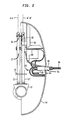
- FIGS. 1 and 2 show a preferred embodiment of a high temperature Coriolis mass flow meter 10 that incorporates the teachings of the present invention.
- flow meter 10 incorporates dual flow conduits 11 and 11′ which are affixed to corresponding manifolds 12 and 12′.
- Manifolds 12 and 12′ are held in alignment by spacer 13 which is a hollow cylinder.
- Manifolds 12 and 12′ and spacer 13 are all made of 316L and 304L type stainless steel, respectively.
- Manifolds 12 and 12′ direct flow through flow meter 10.
- L left side
- R is the outlet of the meter
- left manifold 12 divides the incoming flow into two streams and directs the resulting flow into dual flow conduits 11 and 11′.
- Right manifold 12′ recombines the flow leaving the dual flow conduits into one stream after which it then exits the flow meter.
- Housing 14′ which is described in detail later, fully encloses flow conduits 11 and 11′.
- brace bars 15 are provided between the dual flow conduits. Specifically, brace bars 15 are positioned on the flow conduits adjacent to but spaced apart an equal distance from manifolds 12 and 12′.
- flow meter 10 also includes magnetic driver assembly 16 to resonantly vibrate flow conduits 11 and 11′, in an opposing sinusoidal manner similar to that in which the prongs of a tuning fork vibrate.
- flow conduits 11 and 11′ are preferably made from a suitable one of the widely known nickel-chrome-molybdenum HASTELLOY alloys manufactured by Cabot Corporation of Kokomo, Indiana (which owns the trademark HASTELLOY), such as HASTELLOY alloys C22 or C276 or their equivalents for use in a temperature range of between 500° to 800°F (approximately 260 to 427°C). These alloys are preferred because they do not undergo carbide precipitation at the desired operating temperature range for the meter.
- the term "flow conduit” as used hereinafter specifically means a flow conduit made of an alloy(s) that does not undergo carbide precipitation at the desired operating temperature range of the flow meter and includes conduits made of HASTELLOY alloys C22 and/or C276 or their equivalents.
- high temperature means an operating range for the flow meter from about 500 to about 800°F (approximately 260 to 427°C).
- the high temperature meter disclosed herein can fully and satisfactorily operate at normal ambient room temperatures; however, it is more suitable for use in high temperature applications.
- flow conduits 12 and 12 are dictated by the teachings set forth in United States Patent Application Serial No. 06/914,932 entitled "Density Insensitive Coriolis Mass Flow Rate Meter,” filed October 3, 1986, which now has evolved into U.S. Patent 4,823,613.
- the flow conduits are formed from conduits of homogeneous material that have essentially uniform wall thickness. These conduits are mounted so they can be oscillated and inherently have resonance frequencies for all modes of oscillation in which the ratio of any two resonant frequencies remains constant irrespective of any changes in the density of fluids passing through the conduits. If weights (or other structures) which do not have their masses altered by changes in fluid density, such as e.g.
- Flow meter 10 includes velocity sensors. These sensors are analog velocity sensors which provide analog signals linearly representative of actual differential movement of flow conduits 11 and 11′ over their entire path of motion. When flow conduits 11 and 11′ are vibrating and fluid is flowing therethrough, these flow conduits are deflected about their respective axes A-A and A′-A′(see specifically FIG. 2) by Coriolis forces resulting from the moving fluid. The effects of these deflections are monitored by velocity sensors 17 and 18.
- a detailed description of the mechanical operation of flow meter 10, particularly with respect to the generation of Coriolis forces and measurement of mass flow rate resulting therefrom, is set forth in United States Patents 4,491,025 (issued to J. E.
- velocity sensors 17 and 18 and magnetic drive assembly 16 are discussed hereinbelow.
- velocity sensors 17 and 18 and magnetic drive assembly 16 are mounted to flow conduits 11 and 11′ via V-shaped, two-legged, metallic support clips 20. These clips are vacuum brazed onto flow conduits 11 and 11′. A separate support clip is provided for each coil 22 and each magnet 24 comprising velocity sensors 17 and 18 and magnetic drive assembly 16. To simplify their construction and installation, all support clips 20 are identical, have vertically aligned openings 26 through both legs thereof and are made of 316L or 304L type stainless steel. Support clips are identically positioned on each of the two flow conduits. Since both velocity sensors 17 and 18 are identical, for purposes of brevity, the following discussion will specifically address velocity sensor 18.
- support clips 20 are aligned as adjacent pairs between flow conduits 11 and 11′: one support clip for the magnet, the other for the corresponding coil.
- magnet 24 is mounted on one of the flow conduits, here illustratively flow conduit 11, while the associated coil is mounted on the other flow conduit, here illustratively flow conduit 11′.
- each magnet 24, which is a solid cylinder is press-fitted into a cylindrical 316L type stainless steel sleeve 28 having flange 30 located at one end thereof. The magnet and sleeve assembly is then inserted through central openings 26 in one support clip so as to be in coaxial alignment with coil 22.
- Flange 30 is fastened by welds 31 (here indicated by "X” marks) to the outer surface of one leg of a support clip (see FIG. 3C).
- magnet 24 has a greater mass than that of its corresponding coil 22.
- Counterweight 32 such as a suitable flat washer, is tack welded onto the support clip for each coil 22 so that the two flow conduits are balanced.
- the spacing between flow conduits 11 and 11′ is such that the end of the magnet 24 will remain within annular opening 34 of coil 22.
- Magnet 24 is dimensioned such that it is closely received into annular opening 34 when both are positioned on the flow conduits. This arrangement and structure also applies to magnetic drive assembly 16.
- Flow meter 10 is designed so that coil 22 is always moved within the essentially uniform magnetic field of magnet 24.
- a description of the operation of velocity sensors 17 and 18 for use in single and dual conduit Coriolis mass flow rate meters is set forth in abovementioned United States Patents 4,422,338 and 4,491,025. Though both velocity sensors 17 and 18 generate corresponding output signals, which are generally sinusoidal in nature, one sensor signal leads the other in time. The time difference between the two signals results from the fact that flow conduits 11 and 11′ are deflected by Coriolis forces. The amount of the time difference between the two signals is related to the mass flow rate passing through flow meter 10.
- high temperature magnet means a magnet capable of retaining its magnetic properties between 500 to 800°F and includes magnets made from either ALNICO 8 or ALNICO 9 alloys or their equivalents.
- the bobbin for each velocity sensor needs to be made from a suitable material; while the bobbin for the magnetic drive assembly can be made from a suitable metallic substance such as a stainless steel alloy, if desired.
- Coil matrix 41 is formed on the exterior of bobbin 40 and positioned intermediate the ends of bobbin 40.
- the coil matrix is a coil of fine silver wire 42 whose turns are separated from one another by a hardened ceramic slurry (see FIG. 3B).
- bobbin 40 is made from an injection molded ceramic and includes metal inserts, i.e. mounting inserts 44, and flat metal wire termination posts 46, both preferably made of stainless steel.
- metal inserts i.e. mounting inserts 44, and flat metal wire termination posts 46, both preferably made of stainless steel.
- Use of an injection molded ceramic simplifies manufacture of the bobbins for two reasons. First, it is much easier to precisely mount metal inserts within an injection mold for inclusion within a item that is to be injection molded than to precisely locate a comparable insert into a fired (commonly referred to as a "technical") ceramic. Second, an injection molded ceramic piece has much less dimensional variation than similar pieces made with a technical ceramic.
- Silver wire 42 having a diameter of about 5 mils is wound between two spaced apart flanges 48 located on the exterior of bobbin 40.
- the wire is coated with a sodium silicate ceramic slurry.
- the bobbin is then allowed to dry either in air or in an oven. Once the slurry has dried, the slurry and wire collectively form a solid matrix.
- this slurry increases the effective diameter of the wire hence limiting the number of turns that can be wound on the bobbin, the use of the slurry firmly positions the wire turns within the ceramic matrix thereby ensuring that the coil turns will not electrically short out to one another during subsequent high temperature meter operation.
- the wire is wound onto the bobbin so that the cross-section of the coil is as uniform as possible.
- Each end of the coil wire is wrapped around a termination post 46 a sufficient number of times in order to provide an appropriate strain relief as is commonly known in the art.
- the wrapped wire is then brazed to the post using a standard silver alloy braze.
- Posts 46 serve as a junction/transition point between the coil wire and a flexure ribbon wire described below.
- Coils 22 are secured to flow conduits 11 and 11′, by spot welding mounting inserts 44 to support clips 20 as indicated by welds 50 (see FIG. 3A).
- the materials needed for the bobbin and ceramic slurry should preferably contain no metal oxides at high temperatures. Specifically, at 800°F, a severe reducing atmosphere is present which causes most metal oxides to be reduced into their constituents which includes free oxygen. As such, the metal in the oxide in the bobbin precipitates out onto the coil thereby rendering the entire coil conductive which, in turn, gives rise to spurious signals and, at the least, erroneous meter performance. Alternatively, if metal oxides must be present in the bobbins at room temperature, then these oxides must be chemically bound so that they will not be reduced at high temperatures.
- coil herein means an assembly comprising a noble metal wire wound on a ceramic bobbin with the wire being insulated by a ceramic slurry with the bobbin and slurry containing no reducible metal oxides in the desired operating temperature range.
- drive assembly and “velocity sensor” both mean an assembly that comprises a high temperature magnet and coil.
- a structure for use in a Coriolis meter which is capable of substantially reducing or even eliminating these damping forces is described in the abovementioned United States Patent 4,738,143 (issued to D. Cage et al on April 19, 1988) and in United States Patent Application Serial No. 06/865,715 entitled “Apparatus for Electrically Interconnecting Vibrating Structures” filed May 22, 1986.
- the flexure as used in the present invention is comprised of at least two flat, uninsulated, spaced apart stainless steel ribbon shaped conductors 62. These conductors have a cross-section of typically .002 ⁇ thick by .050 ⁇ wide (approximately .00508 by .127 centimeters).
- An identical flexure is provided for each velocity sensor and the magnetic drive assembly.
- conductors 62 that form the flexure are inserted between wire posts 46 of coils 22 and stationary terminal blocks 64 that are mounted on the housing, specifically through stationary angle brackets 95 that are located adjacent to each coil but spaced apart therefrom.
- Terminal blocks 64 provide an insulating housing for flat ribbon conductors 66 which extend out beyond the terminal block housing and on opposite sides therefrom.
- One flat end of each of conductors 66 and a corresponding post 46 are aligned along their widths and lengths in a parallel spaced apart fashion.
- the flat surfaces of U-shaped conductors 62 are aligned with the corresponding surfaces of post 46 and conductors 66.
- flexure 60 specifically conductors 66, substantially forms a U-shape with its centerline oriented in an essentially parallel fashion to the direction of oscillation of flow conduits 11 and 11′ (see FIG. 3B), this direction being indicated by arrows 90 and 90′ for flow conduits 11 and 11′, respectively.
- This shape and orientation allows for a rolling or wave-like motion of flexure 60 as flow conduits 11 and 11′ oscillate with respect to the stationary terminal blocks 64.
- the alignment of the flat surfaces of post 46 and conductors 62 and between conductors 66 and conductors 62 advantageously permits these components to be assembled using spot welds 67 (see FIG. 3D), provides a large surface area for attachment and provides strain relief for these connections.
- spot welds 67 see FIG. 3D
- the opposite ends of conductors 66 are attached by spot welds to solid, round nickel wire leads 68.
- Leads 68 are insulated along a portion of their length near feed-through 70 (see FIG.
- internal wire leads 68 are connected to external wire leads via conventional nine pin brazed ceramic feed-through 70, as is commonly known in the art.
- Six of these nine wires are from coils of magnetic drive assembly 16 and velocity sensors 17 and 18.
- the remaining three wires are from temperature sensor assembly 72 (see FIG. 1), which illustratively includes a platinum resistance temperature device (RTD), that is used to measure the temperature of the flow conduit.
- RTD platinum resistance temperature device
- internal wire leads would be spliced onto the leads of the RTD to provide sufficient length to reach feed-through 70.
- temperature sensing is used to provide compensation for changes in a spring constant of each flow conduit caused by a change in its temperature from ambient conditions. As can be seen in FIG.
- RTD assembly 72 is affixed to flow conduit 11 via metal sleeve 74 that is welded to the surface of one of the flow conduit.
- a three wire RTD element is inserted into sleeve 74 through one end thereof. Both ends are then crimped to prevent the RTD element from sliding out.
- Tape is normally used to fasten the RTD to the surface of a flow conduit in a Coriolis flow meter that is designed to operate at relatively low temperatures. However, when used in a meter operating at high temperatures, the tape would eventually burn off and, as such, welding is used instead.
- feed-through 70 is provided with metal lip 79. Through use of this lip, the feed-through is secured into hollow cylindrical standoff 80 provided on the interior side of housing 14 by weld 81. The use of the feed-through is required by the need to hermetically seal the meter.
- External leads 82 pass through opening 83 provided in housing 14.
- Round, stranded, nickel wire leads 82 are connected to an external side of wire feed-through 70.
- External leads 82 typically four feet (approximately 1.22 meters) in length, are preferably connected by brazing to the external ends of corresponding pins of feed-through 70.
- each of the nine wires utilize an identical structure within feed-through 70.
- the structure of the feed-through that is used for only one of these wires is specifically shown therein.
- this method of connection provides a strong joint.
- external leads 82 are triple insulated. Specifically, first, external leads 82 are each individually wrapped with mica tape 85, then covered by a polytetrafluoroethylene (PTFE) impregnated, woven fiberglass sheath 86. For illustrative purposes, only one external lead 82 is shown having a sheath 86.
- PTFE polytetrafluoroethylene
- the first 6 to 10 inches (approximately 15 to 25 cm) of these sheaths are baked (annealed) in air at an about 800°F (approximately 427°C).
- the PTFE acts as a binder to prevent fraying prior to annealing.
- the PTFE binder could be eliminated if a suitable heat-treated sheath could be found.
- carbon in the PTFE and/or any oxides in the insulation are both driven off. We have discovered that this baking is necessary in order to avoid carbon buildup on ferrules and feed-through pins that are located on the external side of feed-through 70 during meter operation at a high temperature.
- each of leads 82 carries a corresponding identification tag 87 (here illustratively carrying the numbers one through nine) that specifically identifies that lead for subsequent proper connection to the electronics.
- Housing 14 is not simply a cover for the flow conduits and other internal components. This housing, when installed, maintains an hermetically sealed, inert gas environment for all the internal components of the flow meter.
- housing 14 is fabricated from two standard tank domes (tank heads) 90 formed of plate steel, each having elliptical cross-sections with an illustrative ratio of 2:1 between its major and minor axes. Hence, domes 90, when assembled together, give the flow meter the appearance of an oyster shell. Domes 90 completely enclose flow meter 10. Openings are provided for feed-through 70, purge fitting 92 and inlet and outlet manifolds 12 of flow meter 10. All openings through the housing are welded so that a hermetic seal is achieved.
- a vacuum is drawn on the case via purge fitting 92 to withdraw any air that may be present.
- Hole 94 (see FIG. 1) is provided in spacer 13 to ensure that air residing within the interior of the spacer can subsequently be vented after the spacer is welded between manifolds 12.
- An inert gas such as helium or preferably argon, is then injected into housing 14 via purge fitting 92.
- Purge fitting 92 is then sealed either by a plug or by welding. The inert gas is necessary in order to displace any oxygen that may be inside the housing. At the desired operating temperatures, any air creates an aggressive reducing atmosphere which will corrode the wires and coils. The use of an inert gas prevents this from occurring as well as eliminating the need for a cooling purge.
- Inert gas is injected either at atmospheric pressure or at a reduced pressure. If inert gas at atmospheric pressure is used, then, when the flow meter is heated to 800°F (approximately 427°C), the internal pressure within the housing will increase to approximately 35 pounds per square inch (psi) (approximately 2.45 kilograms/square centimeter). Accordingly, housing 14 must be able to contain this pressurized atmosphere at these operating temperatures. Alternatively, if the inert gas is injected at a reduced pressure, such as 5 psi (approximately .245 kilograms/square centimeter), then the internal pressure at operating temperature will only be about 12 psi (approximately .84 kilograms/square centimeter) or normal ambient pressure. If this latter approach is used, then the housing can be fabricated from sheet steel instead of the tank domes; thus reducing the overall weight and cost of the flow meter.
- Type 316L stainless steel is typically used to fabricate all metallic elements for which a specific alloy or material has not been specified herein.
- the inventive meter is described in the context of use for measuring mass flow rate, since electrical connections to either flow conduit sensor, the drive coil and the RTD temperature sensor are provided through the meter case to the external environment, the inventive meter can also be used as the measuring element in a Coriolis based densitometer in lieu of just as a Coriolis mass flow rate meter. Furthermore, with suitable electronics, the inventive meter can also be used as the measuring element to simultaneously provide both density and mass flow rate measurements for use in those applications that require both measurements of a moving fluid, such as in a net oil computer that provides both volumetric and mass based flow rate and totalized flow measurements of individual oil and water components that constitute an oil-water emulsion.
- conduits of almost any size and shape may be used as long as the conduits can be resonantly oscillated (vibrated) about an axis to establish a non-inertial frame of reference for fluid passing therethrough.
- these conduits may include but are not limited to straight tubes, S-shaped tubes or looped tubes.
- fluid has been shown as entering the manifolds in a direction substantially perpendicular to the flow conduits, each manifold can be adapted to receive and discharge fluid in a direction substantially parallel to or at any angle to the ends of the flow conduits.
- the meter has been shown as containing only two parallel flow conduits, embodiments having a single flow conduit or more than two parallel flow conduits -- such as three, four or even more -- may be used, if desired, provided suitable changes are made to the geometry of the meter in order to accommodate the desired number and orientation of the desired flow conduits.
Landscapes
- Physics & Mathematics (AREA)
- Fluid Mechanics (AREA)
- General Physics & Mathematics (AREA)
- Measuring Volume Flow (AREA)
Applications Claiming Priority (2)
| Application Number | Priority Date | Filing Date | Title |
|---|---|---|---|
| US07/257,806 US4876898A (en) | 1988-10-13 | 1988-10-13 | High temperature coriolis mass flow rate meter |
| US257806 | 1988-10-13 |
Publications (3)
| Publication Number | Publication Date |
|---|---|
| EP0364054A2 true EP0364054A2 (de) | 1990-04-18 |
| EP0364054A3 EP0364054A3 (en) | 1990-09-05 |
| EP0364054B1 EP0364054B1 (de) | 1994-05-11 |
Family
ID=22977830
Family Applications (1)
| Application Number | Title | Priority Date | Filing Date |
|---|---|---|---|
| EP89202571A Expired - Lifetime EP0364054B1 (de) | 1988-10-13 | 1989-10-12 | Nach dem Coriolis-Prinzip arbeitender Hochtemperatur-Massendurchflussmesser |
Country Status (7)
| Country | Link |
|---|---|
| US (1) | US4876898A (de) |
| EP (1) | EP0364054B1 (de) |
| JP (1) | JPH0778441B2 (de) |
| AU (1) | AU609335B2 (de) |
| BR (1) | BR8905105A (de) |
| CA (1) | CA1323215C (de) |
| DE (1) | DE68915241T2 (de) |
Cited By (4)
| Publication number | Priority date | Publication date | Assignee | Title |
|---|---|---|---|---|
| DE19601349A1 (de) * | 1996-01-17 | 1997-07-24 | Danfoss As | Durchflußmesser für kleine Mengen |
| WO1999005480A1 (en) * | 1997-07-28 | 1999-02-04 | Micro Motion, Inc. | Multiple resistive sensors for a coriolis effect mass flowmeter |
| WO2000012971A1 (en) * | 1998-08-26 | 2000-03-09 | Micro Motion, Inc. | High temperature drive system for a coriolis mass flowmeter |
| WO2019029941A1 (de) * | 2017-08-09 | 2019-02-14 | Endress+Hauser Flowtec Ag | SPULE SOWIE MEßWANDLER MIT EINER SOLCHEN SPULE |
Families Citing this family (66)
| Publication number | Priority date | Publication date | Assignee | Title |
|---|---|---|---|---|
| EP0469448A1 (de) * | 1990-07-28 | 1992-02-05 | KROHNE MESSTECHNIK MASSAMETRON GmbH & Co. KG | Massendurchflussmessgerät |
| US5231884A (en) * | 1991-07-11 | 1993-08-03 | Micro Motion, Inc. | Technique for substantially eliminating temperature induced measurement errors from a coriolis meter |
| US5374810A (en) * | 1992-06-05 | 1994-12-20 | Gantt; Jackie L. | Induction heating transformer and method of winding same |
| DE4408168C2 (de) * | 1993-11-18 | 1995-08-31 | Ulrich Dipl Ing Elsen | Vorrichtung zum Messen der Masse eines pumpfähigen in einer Rohrleitung fließenden Mediums |
| ES2145244T3 (es) * | 1994-05-26 | 2000-07-01 | Flowtec Ag | Detector de caudal masico segun el principio de coriolis. |
| US5546814A (en) * | 1994-10-26 | 1996-08-20 | The Foxboro Company | Parallel-flow coriolis-type mass flowmeter with flow-dividing manifold |
| DE19604181C2 (de) * | 1996-02-06 | 1998-08-20 | Ulrich Dipl Ing Elsen | Druckdichte und temperaturresistente austauschbare Kabelgehäusedurchführung für Masse-Durchflußmesser |
| DE19719587A1 (de) * | 1997-05-09 | 1998-11-19 | Bailey Fischer & Porter Gmbh | Verfahren und Einrichtung zur Erkennung und Kompensation von Nullpunkteinflüssen auf Coriolis-Massedurchflußmesser |
| US6796173B1 (en) | 1998-10-09 | 2004-09-28 | Fti Flow Technology, Inc. | Fuel flowmeter |
| US6513392B1 (en) * | 1998-12-08 | 2003-02-04 | Emerson Electric Co. | Coriolis mass flow controller |
| US6748813B1 (en) | 1998-12-08 | 2004-06-15 | Emerson Electric Company | Coriolis mass flow controller |
| US6526839B1 (en) * | 1998-12-08 | 2003-03-04 | Emerson Electric Co. | Coriolis mass flow controller and capacitive pick off sensor |
| JP3656947B2 (ja) * | 1999-10-05 | 2005-06-08 | 株式会社オーバル | コリオリ質量流量計 |
| US6776052B2 (en) * | 1999-10-29 | 2004-08-17 | Micro Motion, Inc. | Coriolis flowmeter having a reduced flag dimension for handling large mass flows |
| DE10017963C2 (de) * | 2000-04-12 | 2003-01-30 | Krohne Ag Basel | Massendurchflussmessgerät |
| US6711958B2 (en) * | 2000-05-12 | 2004-03-30 | Endress + Hauser Flowtec Ag | Coriolis mass flow rate/density/viscoy sensor with two bent measuring tubes |
| DK1421349T3 (en) * | 2001-08-29 | 2016-05-30 | Flowtec Ag | SENSOR on the vibration |
| WO2003021202A1 (de) * | 2001-08-29 | 2003-03-13 | Endress + Hauser Flowtec Ag | Messaufnehmer vom vibrationstyp |
| US6957587B2 (en) * | 2001-08-29 | 2005-10-25 | Endress + Hauser Flowtech, Ag | Vibratory transducer |
| US8100552B2 (en) * | 2002-07-12 | 2012-01-24 | Yechezkal Evan Spero | Multiple light-source illuminating system |
| US7051598B2 (en) * | 2003-03-21 | 2006-05-30 | Endress + Hauser Flowtec Ag | Magnetic circuit arrangement for a sensor |
| US7040181B2 (en) * | 2004-03-19 | 2006-05-09 | Endress + Hauser Flowtec Ag | Coriolis mass measuring device |
| US7284449B2 (en) * | 2004-03-19 | 2007-10-23 | Endress + Hauser Flowtec Ag | In-line measuring device |
| DE102004018326B4 (de) | 2004-04-13 | 2023-02-23 | Endress + Hauser Flowtec Ag | Vorrichtung und Verfahren zum Messen einer Dichte und/oder einer Viskosität eines Fluids |
| JP5144266B2 (ja) * | 2004-09-09 | 2013-02-13 | マイクロ・モーション・インコーポレーテッド | 2つの振動モード間のコリオリ結合を測定することにより管路での流量を測定する方法及び装置 |
| DE102005039577B3 (de) * | 2005-08-19 | 2007-05-10 | Krohne Ag | Massendurchflußmeßgerät |
| DE102005046319A1 (de) | 2005-09-27 | 2007-03-29 | Endress + Hauser Flowtec Ag | Verfahren zum Messen eines in einer Rohrleitung strömenden Mediums sowie Meßsystem dafür |
| JP4955005B2 (ja) | 2005-10-06 | 2012-06-20 | マイクロ・モーション・インコーポレーテッド | 磁石アッセンブリ |
| US7325461B2 (en) * | 2005-12-08 | 2008-02-05 | Endress + Hauser Flowtec Ag | Measurement transducer of vibration-type |
| US7360452B2 (en) * | 2005-12-27 | 2008-04-22 | Endress + Hauser Flowtec Ag | In-line measuring devices and method for compensation measurement errors in in-line measuring devices |
| WO2007074055A1 (en) | 2005-12-27 | 2007-07-05 | Endress+Hauser Flowtec Ag | In-line measuring devices and method for compensating measurement errors in in-line measuring devices |
| US7360453B2 (en) * | 2005-12-27 | 2008-04-22 | Endress + Hauser Flowtec Ag | In-line measuring devices and method for compensation measurement errors in in-line measuring devices |
| DE102006062600B4 (de) | 2006-12-29 | 2023-12-21 | Endress + Hauser Flowtec Ag | Verfahren zum Inbetriebnehmen und/oder Überwachen eines In-Line-Meßgeräts |
| DE102008016235A1 (de) | 2008-03-27 | 2009-10-01 | Endress + Hauser Flowtec Ag | Verfahren zum Betreiben eines auf einer rotierenden Karussell-Abfüllmachine angeordneten Meßgeräts |
| CN101990727B (zh) * | 2008-04-04 | 2013-11-20 | 微动公司 | 包括陶瓷基涂层的穿导件和涂覆陶瓷基涂层于穿导件之法 |
| CN102037336A (zh) * | 2008-05-09 | 2011-04-27 | 微动公司 | 具有作为用于驱动器构件和传感器构件的支撑部的中心固定板的双管科里奥利流量计 |
| DE102008002217A1 (de) * | 2008-06-04 | 2009-12-10 | Endress + Hauser Flowtec Ag | Vorrichtung zur Bestimmung und/oder Überwachung eines Strömungsparameters |
| DE102008002215A1 (de) * | 2008-06-04 | 2009-12-10 | Endress + Hauser Flowtec Ag | Vorrichtung zur Bestimmung und/oder Überwachung eines Strömungsparameters |
| DE102009046043A1 (de) * | 2009-10-27 | 2011-05-05 | Endress + Hauser Flowtec Ag | Messwandler vom Vibrationstyp |
| DE102009057912B4 (de) * | 2009-12-11 | 2013-07-25 | Krohne Ag | Coriolis-Massendurchflussmessgerät |
| DE102010018222B4 (de) * | 2010-04-23 | 2012-03-22 | Krohne Ag | Coriolis-Massedurchflussmessgerät |
| JP5916854B2 (ja) * | 2011-07-07 | 2016-05-11 | マイクロ モーション インコーポレイテッド | 振動計用の改良された電気構成 |
| CA2852399C (en) * | 2011-10-26 | 2019-02-05 | Micro Motion, Inc. | Collocated sensor for a vibrating fluid meter |
| CA2909151C (en) * | 2013-04-10 | 2021-08-17 | Euler Ceramic Systems As | High voltage electric power feed-through apparatus |
| WO2015090776A1 (de) | 2013-12-20 | 2015-06-25 | Endress+Hauser Flowtec Ag | Spule |
| DE102013114731A1 (de) | 2013-12-20 | 2015-06-25 | Endress+Hauser Flowtec Ag | Spule |
| DE102014109116A1 (de) * | 2014-06-30 | 2015-12-31 | Krohne Ag | Coriolis-Massedurchflussmessgerät |
| US9368264B2 (en) * | 2014-09-08 | 2016-06-14 | Micro Motion, Inc. | Magnet keeper assembly and related method |
| CN105865555B (zh) * | 2016-05-24 | 2018-08-24 | 合肥工业大学 | 一种科氏质量流量计的抗高温模拟驱动电路 |
| DE102017131199A1 (de) | 2017-12-22 | 2019-06-27 | Endress + Hauser Flowtec Ag | Coriolis-Massendurchfluß-Meßgerät |
| DE102018001778A1 (de) * | 2018-03-06 | 2019-09-12 | Rota Yokogawa Gmbh & Co. Kg | Massendurchfluss- und Dichtemesser nach dem Coriolis-Prinzip mit geringer Druckabhängigkeit und Verfahren zur Herstellung |
| CN112088291A (zh) * | 2018-05-15 | 2020-12-15 | 高准公司 | 用于高温的线圈换能器 |
| US12174212B2 (en) | 2018-12-20 | 2024-12-24 | Endress+Hauser Flowtec Ag | Coriolis mass flow meter |
| DE102018133117A1 (de) | 2018-12-20 | 2020-06-25 | Endress+Hauser Flowtec Ag | Coriolis-Massendurchfluß-Meßgerät |
| US12152920B2 (en) | 2018-12-21 | 2024-11-26 | Endress+Hauser Flowtec Ag | Coriolis mass flowmeter with magnetic field detector |
| DE102019133610A1 (de) | 2019-12-09 | 2021-06-10 | Endress + Hauser Flowtec Ag | Vibronisches Meßsystem zum Messen eines Massestroms eines fluiden Meßstoff |
| DE102020121681A1 (de) | 2020-08-18 | 2022-02-24 | Endress+Hauser Flowtec Ag | Coriolis-Durchflussmessgerät |
| DE102020127382A1 (de) | 2020-10-16 | 2022-04-21 | Endress+Hauser Flowtec Ag | Verfahren zum Überprüfen eines vibronischen Meßsystems |
| DE102021131866A1 (de) | 2021-12-03 | 2023-06-07 | Endress+Hauser Flowtec Ag | Verfahren zum Detektieren eines Fremdkörpers in einem Medium |
| CN114812715A (zh) * | 2022-03-02 | 2022-07-29 | 沃森测控技术(河北)有限公司 | 一种采用内置支撑结构的科氏质量流量计 |
| DE102022112523A1 (de) | 2022-05-18 | 2023-11-23 | Endress+Hauser Flowtec Ag | Vibronisches Meßsystem |
| DE102022114039A1 (de) | 2022-06-02 | 2023-12-07 | Endress+Hauser Flowtec Ag | Verbindungskabel sowie damit gebildetes Meßgerät |
| DE102022116111A1 (de) | 2022-06-28 | 2023-12-28 | Endress+Hauser Flowtec Ag | Vibronisches Meßsystem |
| DE102022133715A1 (de) * | 2022-12-16 | 2024-06-27 | Endress + Hauser Flowtec Ag | Modulares Coriolis-Durchflussmessgerät |
| EP4675239A3 (de) * | 2023-02-21 | 2026-02-25 | Micro Motion, Inc. | Elektromagnetischer wandler für symmetrische schwingungen einer symmetrisch schwingenden vorrichtung |
| EP4677314A1 (de) * | 2023-03-09 | 2026-01-14 | Micro Motion, Inc. | Messaufnehmer vom vibrationstyp mit von den messspulen ausgehenden drahtbiegungen und zugehöriges verfahren |
Family Cites Families (12)
| Publication number | Priority date | Publication date | Assignee | Title |
|---|---|---|---|---|
| US2982888A (en) * | 1957-05-23 | 1961-05-02 | Rea Magnet Wire Company Inc | Sleeve type encapsulated electrical component |
| US3223553A (en) * | 1962-01-10 | 1965-12-14 | Anaconda Wire & Cable Co | Electrical insulating glass composition and apparatus encapsulated therewith |
| US3308414A (en) * | 1964-01-14 | 1967-03-07 | Anaconda Wire & Cable Co | Porous-refractory encapsulant for cous and coil encapsulated therewith |
| US4422338A (en) * | 1981-02-17 | 1983-12-27 | Micro Motion, Inc. | Method and apparatus for mass flow measurement |
| US4503605A (en) * | 1981-05-15 | 1985-03-12 | Westinghouse Electric Corp. | Method of making a cellulose-free electrical winding |
| US4406056A (en) * | 1981-10-02 | 1983-09-27 | Westinghouse Electric Corp. | Method of making a cellulose-free transformer coil |
| US4491025A (en) * | 1982-11-03 | 1985-01-01 | Micro Motion, Inc. | Parallel path Coriolis mass flow rate meter |
| US4554730A (en) * | 1984-01-09 | 1985-11-26 | Westinghouse Electric Corp. | Method of making a void-free non-cellulose electrical winding |
| DE3443234A1 (de) * | 1984-11-27 | 1986-06-05 | Danfoss A/S, Nordborg | Massendurchfluss-messgeraet nach dem coriolis-prinzip |
| US4738143A (en) * | 1985-08-29 | 1988-04-19 | Micro Motion, Incorporated | High temperature Coriolis mass flow rate meter |
| JPS6312720U (de) * | 1986-07-11 | 1988-01-27 | ||
| US4823592A (en) * | 1988-02-05 | 1989-04-25 | Micro Motion, Inc. | Test apparatus for proving the performance of mass flow meters |
-
1988
- 1988-10-13 US US07/257,806 patent/US4876898A/en not_active Expired - Lifetime
-
1989
- 1989-08-18 CA CA000608763A patent/CA1323215C/en not_active Expired - Lifetime
- 1989-10-06 BR BR898905105A patent/BR8905105A/pt not_active IP Right Cessation
- 1989-10-12 JP JP1264083A patent/JPH0778441B2/ja not_active Expired - Lifetime
- 1989-10-12 DE DE68915241T patent/DE68915241T2/de not_active Expired - Lifetime
- 1989-10-12 EP EP89202571A patent/EP0364054B1/de not_active Expired - Lifetime
- 1989-10-12 AU AU42763/89A patent/AU609335B2/en not_active Expired
Cited By (10)
| Publication number | Priority date | Publication date | Assignee | Title |
|---|---|---|---|---|
| DE19601349A1 (de) * | 1996-01-17 | 1997-07-24 | Danfoss As | Durchflußmesser für kleine Mengen |
| WO1999005480A1 (en) * | 1997-07-28 | 1999-02-04 | Micro Motion, Inc. | Multiple resistive sensors for a coriolis effect mass flowmeter |
| US5929344A (en) * | 1997-07-28 | 1999-07-27 | Micro Motion, Inc. | Circuitry for reducing the number of conductors for multiple resistive sensors on a coriolis effect mass flowmeter |
| MY119929A (en) * | 1997-07-28 | 2005-08-30 | Micro Motion Inc | Multiple resistive sensors for a coriolis effect mass flowmeter |
| WO2000012971A1 (en) * | 1998-08-26 | 2000-03-09 | Micro Motion, Inc. | High temperature drive system for a coriolis mass flowmeter |
| RU2238525C2 (ru) * | 1998-08-26 | 2004-10-20 | Майкро Моушн, Инк. | Высокотемпературная приводная система для массового расходомера кориолиса |
| KR100486155B1 (ko) * | 1998-08-26 | 2005-04-29 | 마이크로 모우션, 인코포레이티드 | 코리올리 질량 유량계용 고온 구동 시스템 |
| WO2019029941A1 (de) * | 2017-08-09 | 2019-02-14 | Endress+Hauser Flowtec Ag | SPULE SOWIE MEßWANDLER MIT EINER SOLCHEN SPULE |
| CN110998249A (zh) * | 2017-08-09 | 2020-04-10 | 恩德斯+豪斯流量技术股份有限公司 | 线圈和具有线圈的变压器 |
| US11783976B2 (en) | 2017-08-09 | 2023-10-10 | Endress+Hauser Flowtec Ag | Coil and transformer having such a coil |
Also Published As
| Publication number | Publication date |
|---|---|
| JPH0778441B2 (ja) | 1995-08-23 |
| JPH02150724A (ja) | 1990-06-11 |
| CA1323215C (en) | 1993-10-19 |
| EP0364054B1 (de) | 1994-05-11 |
| US4876898A (en) | 1989-10-31 |
| AU609335B2 (en) | 1991-04-26 |
| EP0364054A3 (en) | 1990-09-05 |
| DE68915241D1 (de) | 1994-06-16 |
| AU4276389A (en) | 1990-04-26 |
| DE68915241T2 (de) | 1994-08-18 |
| BR8905105A (pt) | 1990-05-15 |
Similar Documents
| Publication | Publication Date | Title |
|---|---|---|
| EP0364054B1 (de) | Nach dem Coriolis-Prinzip arbeitender Hochtemperatur-Massendurchflussmesser | |
| US4738143A (en) | High temperature Coriolis mass flow rate meter | |
| US6711958B2 (en) | Coriolis mass flow rate/density/viscoy sensor with two bent measuring tubes | |
| EP0235274B1 (de) | Sensormontage für schwingende strukturen | |
| US5301557A (en) | Stability coriolis mass flow meter | |
| KR940000140B1 (ko) | 열식 유량계 | |
| FI68318B (fi) | Tryckmaetanordning av vibrationstraodtypen | |
| US20210072061A1 (en) | Coil transducer for elevated temperatures | |
| US7275448B2 (en) | Magnetic circuit arrangement for a sensor | |
| CN110998249A (zh) | 线圈和具有线圈的变压器 | |
| JPH10148554A (ja) | 流量計 | |
| CN1058565C (zh) | 科氏质量流量计 | |
| EP4278157B1 (de) | Elektrische verbindung mit verbessertem durchführungselement | |
| JP2966337B2 (ja) | コリオリ流量計 | |
| CA1268829A (en) | Apparatus for electrically interconnecting vibrating structures | |
| CA3204715C (en) | Electrical junction having an improved feedthrough element | |
| RU2823118C1 (ru) | Электрическое соединение, имеющее улучшенный проходной элемент | |
| USRE36376E (en) | Stability coriolis mass flow meter | |
| HK40090873A (en) | Electrical junction having an improved feedthrough element |
Legal Events
| Date | Code | Title | Description |
|---|---|---|---|
| PUAI | Public reference made under article 153(3) epc to a published international application that has entered the european phase |
Free format text: ORIGINAL CODE: 0009012 |
|
| AK | Designated contracting states |
Kind code of ref document: A2 Designated state(s): BE DE FR GB IT LU NL |
|
| PUAL | Search report despatched |
Free format text: ORIGINAL CODE: 0009013 |
|
| AK | Designated contracting states |
Kind code of ref document: A3 Designated state(s): BE DE FR GB IT LU NL |
|
| 17P | Request for examination filed |
Effective date: 19901219 |
|
| 17Q | First examination report despatched |
Effective date: 19920723 |
|
| GRAA | (expected) grant |
Free format text: ORIGINAL CODE: 0009210 |
|
| AK | Designated contracting states |
Kind code of ref document: B1 Designated state(s): BE DE FR GB IT LU NL |
|
| REF | Corresponds to: |
Ref document number: 68915241 Country of ref document: DE Date of ref document: 19940616 |
|
| ITF | It: translation for a ep patent filed | ||
| ET | Fr: translation filed | ||
| ITTA | It: last paid annual fee | ||
| PLBI | Opposition filed |
Free format text: ORIGINAL CODE: 0009260 |
|
| PLBI | Opposition filed |
Free format text: ORIGINAL CODE: 0009260 |
|
| 26 | Opposition filed |
Opponent name: ENDRESS + HAUSER FLOWTEC AG Effective date: 19950203 |
|
| 26 | Opposition filed |
Opponent name: KROHNE MESSTECHNIK GMBH & CO. KG Effective date: 19950213 Opponent name: ENDRESS + HAUSER FLOWTEC AG Effective date: 19950203 |
|
| NLR1 | Nl: opposition has been filed with the epo |
Opponent name: ENDRESS Opponent name: HAUSER,FLOWTEC AG |
|
| NLR1 | Nl: opposition has been filed with the epo |
Opponent name: KROHNE MESSTECHNIK GMBH & CO, KG |
|
| PLBO | Opposition rejected |
Free format text: ORIGINAL CODE: EPIDOS REJO |
|
| APAC | Appeal dossier modified |
Free format text: ORIGINAL CODE: EPIDOS NOAPO |
|
| APAE | Appeal reference modified |
Free format text: ORIGINAL CODE: EPIDOS REFNO |
|
| APAC | Appeal dossier modified |
Free format text: ORIGINAL CODE: EPIDOS NOAPO |
|
| PLBN | Opposition rejected |
Free format text: ORIGINAL CODE: 0009273 |
|
| STAA | Information on the status of an ep patent application or granted ep patent |
Free format text: STATUS: OPPOSITION REJECTED |
|
| 27O | Opposition rejected |
Effective date: 19980209 |
|
| NLR2 | Nl: decision of opposition | ||
| PGFP | Annual fee paid to national office [announced via postgrant information from national office to epo] |
Ref country code: BE Payment date: 19981118 Year of fee payment: 10 |
|
| PGFP | Annual fee paid to national office [announced via postgrant information from national office to epo] |
Ref country code: LU Payment date: 19990922 Year of fee payment: 11 |
|
| PG25 | Lapsed in a contracting state [announced via postgrant information from national office to epo] |
Ref country code: BE Free format text: LAPSE BECAUSE OF NON-PAYMENT OF DUE FEES Effective date: 19991031 |
|
| BERE | Be: lapsed |
Owner name: MICRO MOTION INC. Effective date: 19991031 |
|
| PG25 | Lapsed in a contracting state [announced via postgrant information from national office to epo] |
Ref country code: LU Free format text: LAPSE BECAUSE OF NON-PAYMENT OF DUE FEES Effective date: 20001012 |
|
| REG | Reference to a national code |
Ref country code: GB Ref legal event code: IF02 |
|
| APAH | Appeal reference modified |
Free format text: ORIGINAL CODE: EPIDOSCREFNO |
|
| PGFP | Annual fee paid to national office [announced via postgrant information from national office to epo] |
Ref country code: NL Payment date: 20081005 Year of fee payment: 20 |
|
| PGFP | Annual fee paid to national office [announced via postgrant information from national office to epo] |
Ref country code: DE Payment date: 20081014 Year of fee payment: 20 |
|
| PGFP | Annual fee paid to national office [announced via postgrant information from national office to epo] |
Ref country code: IT Payment date: 20081028 Year of fee payment: 20 |
|
| PGFP | Annual fee paid to national office [announced via postgrant information from national office to epo] |
Ref country code: FR Payment date: 20081014 Year of fee payment: 20 |
|
| PGFP | Annual fee paid to national office [announced via postgrant information from national office to epo] |
Ref country code: GB Payment date: 20081008 Year of fee payment: 20 |
|
| REG | Reference to a national code |
Ref country code: GB Ref legal event code: PE20 Expiry date: 20091011 |
|
| NLV7 | Nl: ceased due to reaching the maximum lifetime of a patent | ||
| PG25 | Lapsed in a contracting state [announced via postgrant information from national office to epo] |
Ref country code: NL Free format text: LAPSE BECAUSE OF EXPIRATION OF PROTECTION Effective date: 20091012 |
|
| PG25 | Lapsed in a contracting state [announced via postgrant information from national office to epo] |
Ref country code: GB Free format text: LAPSE BECAUSE OF EXPIRATION OF PROTECTION Effective date: 20091011 |