EP0364057A2 - Profilsteuersystem für eine gegebene gekrümmte Fläche - Google Patents
Profilsteuersystem für eine gegebene gekrümmte Fläche Download PDFInfo
- Publication number
- EP0364057A2 EP0364057A2 EP89202594A EP89202594A EP0364057A2 EP 0364057 A2 EP0364057 A2 EP 0364057A2 EP 89202594 A EP89202594 A EP 89202594A EP 89202594 A EP89202594 A EP 89202594A EP 0364057 A2 EP0364057 A2 EP 0364057A2
- Authority
- EP
- European Patent Office
- Prior art keywords
- velocity
- force
- computing
- command
- working tool
- Prior art date
- Legal status (The legal status is an assumption and is not a legal conclusion. Google has not performed a legal analysis and makes no representation as to the accuracy of the status listed.)
- Granted
Links
Images


Classifications
-
- G—PHYSICS
- G05—CONTROLLING; REGULATING
- G05B—CONTROL OR REGULATING SYSTEMS IN GENERAL; FUNCTIONAL ELEMENTS OF SUCH SYSTEMS; MONITORING OR TESTING ARRANGEMENTS FOR SUCH SYSTEMS OR ELEMENTS
- G05B19/00—Program-control systems
- G05B19/02—Program-control systems electric
- G05B19/18—Numerical control [NC], i.e. automatically operating machines, in particular machine tools, e.g. in a manufacturing environment, so as to execute positioning, movement or co-ordinated operations by means of program data in numerical form
- G05B19/41—Numerical control [NC], i.e. automatically operating machines, in particular machine tools, e.g. in a manufacturing environment, so as to execute positioning, movement or co-ordinated operations by means of program data in numerical form characterised by interpolation, e.g. the computation of intermediate points between programmed end points to define the path to be followed and the rate of travel along that path
-
- B—PERFORMING OPERATIONS; TRANSPORTING
- B25—HAND TOOLS; PORTABLE POWER-DRIVEN TOOLS; MANIPULATORS
- B25J—MANIPULATORS; CHAMBERS PROVIDED WITH MANIPULATION DEVICES
- B25J9/00—Program-controlled manipulators
- B25J9/16—Program controls
- B25J9/1679—Program controls characterised by the tasks executed
- B25J9/1684—Tracking a line or surface by means of sensors
-
- G—PHYSICS
- G05—CONTROLLING; REGULATING
- G05B—CONTROL OR REGULATING SYSTEMS IN GENERAL; FUNCTIONAL ELEMENTS OF SUCH SYSTEMS; MONITORING OR TESTING ARRANGEMENTS FOR SUCH SYSTEMS OR ELEMENTS
- G05B2219/00—Program-control systems
- G05B2219/30—Nc systems
- G05B2219/37—Measurements
- G05B2219/37357—Force, pressure, weight or deflection
-
- G—PHYSICS
- G05—CONTROLLING; REGULATING
- G05B—CONTROL OR REGULATING SYSTEMS IN GENERAL; FUNCTIONAL ELEMENTS OF SUCH SYSTEMS; MONITORING OR TESTING ARRANGEMENTS FOR SUCH SYSTEMS OR ELEMENTS
- G05B2219/00—Program-control systems
- G05B2219/30—Nc systems
- G05B2219/45—Nc applications
- G05B2219/45151—Deburring
-
- G—PHYSICS
- G05—CONTROLLING; REGULATING
- G05B—CONTROL OR REGULATING SYSTEMS IN GENERAL; FUNCTIONAL ELEMENTS OF SUCH SYSTEMS; MONITORING OR TESTING ARRANGEMENTS FOR SUCH SYSTEMS OR ELEMENTS
- G05B2219/00—Program-control systems
- G05B2219/30—Nc systems
- G05B2219/49—Nc machine tool, till multiple
- G05B2219/49362—Tool, probe at constant height to surface during machining
Definitions
- the present invention relates to profiling control systems which use multi-degree-of-freedom working machines such as a robot, a machine tool and the like which have at least two degrees of freedom and, more particularly, to a profiling control system for controlling, by means of position and force, a multi-degree-of-freedom working machine such as a robot, a machine tool or the like which performs a profiling operation such as deburring, curved-surface polishing, a teaching, a measurement of configuration of a curved surface or the like, thereby profiling a given curved surface.
- a profiling control system for controlling, by means of position and force, a multi-degree-of-freedom working machine such as a robot, a machine tool or the like which performs a profiling operation such as deburring, curved-surface polishing, a teaching, a measurement of configuration of a curved surface or the like, thereby profiling a given curved surface.
- the virtual compliance control can be said to be a control system which includes the hybrid control and the compliance control.
- a curved-surface profiling operation in which a work surface is profiled to effect surface polishing, deburring or the like.
- a working tool of the robot is controlled so as to move in profile of the work surface.
- the force and moment applied to the working tool are detected by a force sensor.
- a moving direction of the working tool is an x-axis direction
- an axial direction of the working tool is a z-axis direction. Description will be made in an x - z plane, for convenience.
- the values of k and c increase to be hardened, in the x-axis direction, and the working tool is fed at a velocity v x by the position control.
- k 0, to release restriction of the position.
- the working tool is urged with a target force f r by the force control.
- the force detected by the force sensor is f
- the conventional profiling control system has a limit in profiling a given curved surface.
- a profiling control system which uses a multi-degree-of-freedom working machine having at least two degrees of freedom
- the profiling control system comprising: at least one force control loop including means for detecting force applied to a working tool from a work surface, means for taking an error between the detected force and a command f ro of urging force of the working tool, which is set beforehand, means for computing a velocity command u z of the working tool on the basis of the error, and means for moving the multi-degree-of-freedom working machine on the basis of the velocity command u z ; means for commanding at least one velocity command u x of the working tool; and means for moving the multi-degree-of-freedom working machine on the basis of the velocity command u x
- the profiling control system comprises: first control means for providing a moving velocity v zof in an urging direction, of the working tool, which occurs due to a gradient tan ⁇ of the work surface with respect to
- the moving velocity v zof is provided in the first control means.
- the controlled variable of the force control loop is corrected by the use of the moving velocity v zof , to cancel the force f of due to the velocity v zof .
- the urging force of the working tool is substantially coincident with the command f ro , so that profiling at the desired velocity in accordance with the velocity command v x is made possible.
- the commanding means may be means in the position control loop in which a position of the working tool moving on the work surface is detected, an error is taken between the detected position and a beforehand set command of the position of the working tool, and the velocity command u x of the working tool is computed on the basis of the error.
- the aforesaid means may be means in the velocity control loop in which a velocity of the working tool moving on the work surface is detected, an error is taken between the detected velocity and a beforehand set command of the velocity of the working tool, and the velocity command u x of the working tool is computed on the basis of the error.
- a command of a position of the working tool and "a command of a velocity of the working tool” obtained from the position information stored as the taught data may be used in substitution respectively for "the beforehand set command of the position of the working tool” and "the beforehand set command of the velocity of the working tool".
- the aforementioned means may be means which can command the velocity command u x directly by operation of an operator such as a joy-stick, a keyboard and the like.
- the first control means may include first computing means for computing the gradient tan ⁇ of the work surface, second computing means for computing the feed velocity v x of the working tool fed with said velocity command u x ; and third computing means for computing the moving velocity v zof in the urging direction from the gradient tan ⁇ obtained by the first computing means and the feed velocity v x obtained by said second computing means.
- the first computing means is constructed by means for detecting a position of the working tool which moves on the work surface, and means for computing the gradient tan ⁇ of the work surface from two positions including a present point of the working tool on the work surface, which is detected by the detecting means. This construction is adequate for computation during the profiling operation, since the two positions on the work surface are used as the detecting value.
- the first computing means may include means for computing the gradient tan ⁇ of the work surface from a direction of the feed velocity vector v command v x and a direction of the force detected by the force detecting means. This construction is also adequate for computation during the profiling operation.
- the first computing means may include fourth means for computing the gradient tan ⁇ of the work surface, means for setting a feed target velocity v xyo of the working tool, and fifth computing means for computing the moving velocity v zof in the urging direction from the gradient tan ⁇ obtained by the first computing means and said feed target velocity v xyo .
- the fourth computing means preferably includes means for detecting a position of the working tool which moves on the work surface, means for beforehand setting a feed-target position of the working tool, means for computing a feed-direction vector m in a direction perpendicular to the urging direction of the working tool from two positions which include a present position of the working tool on the work surface, detected by the detecting means, and a feed-target position set beforehand in the setting means, and means for computing the gradient tan ⁇ of the work surface from the feed-direction vector m and a direction of the force detected by the force detecting means. Since the feed-target position set beforehand as one of the two positions is used, the above arrangement is adequate for computation at start of the profiling operation in which the working tool does not yet move.
- the force detecting means is used which can detect forces at least in three axis directions perpendicular to each other, applied to the working tool.
- the first control means computes the gradient tan a of the work surface, and the gradient tan ⁇ is used to compute the moving velocity v vof .
- the moving velocity v vof may be computed without the use of the gradient tan ⁇ .
- the first control means may include means for detecting a position of the working tool which moves on the work surface, and sixth computing means for computing the moving velocity v zof in the urging direction from two positions which include a present point of the working tool on the work surface, which is detected by the detecting means, and from a moving time of the two positions. In this case, since it is unnecessary to compute the gradient, the computation can be made easy, and a high-speed computation treatment is made possible.
- the first control means may take such a construction that the predicted value is stored and is used.
- the first control means may include means for beforehand storing the gradient tan ⁇ of the work surface, means for setting a feed target velocity v xyo of the working tool, and seventh computing means for computing the moving velocity v zof in the urging direction from the gradient tan ⁇ stored beforehand and the feed target velocity v xyo .
- the gradient tan ⁇ stored beforehand since the gradient tan ⁇ stored beforehand is used, a computing amount can be reduced less than the aforesaid case where the gradient tan ⁇ of the work surface is computed at the real time. Thus, a high-velocity computing treatment can be made possible.
- the second control means may include eighth computing means for computing the force f of occurring due to the moving velocity v zof in the urging direction, and ninth computing means for subtracting the force f of from the command f ro of the urging force of the force control loop, to compute a new command f r of the urging force.
- the second control means include tenth computing means for using the moving velocity v zof in the urging direction as a velocity correcting value v zc and adding the velocity correcting value v zc to the velocity command u zo of the force control loop, to compute a new velocity command u z .
- the second control means may subtract the force f of from the urging-force command f ro to compute a new urging-force command f r , thereby profiling the work surface while the latter is urged with the force command f ro .
- the similar results may be obtained in which the moving velocity v zof in the urging direction is brought to the velocity correcting value v zc to add the velocity correcting value v zc to the velocity command u zo , thereby computing a new velocity command u z .
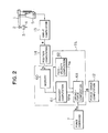
- a robot 1 of articulated type having six degrees of freedom which is an example of a multi-degree-of-freedom working machine, comprises a hand 2 to which a working tool 4 is mounted.
- the working tool 4 has its position and posture (hereinafter referred to as "position/posture”) controlled by driving of drive motors (not shown) which drive the robot 1 around its joints.
- a profiling control system 6 of the embodiment with respect to such robot 1 comprises detecting means which includes a force sensor 3 mounted between the hand 2 and the working tool 4 for detecting a force and a moment (hereinafter referred to as "force/moment") applied to the working tool 4, and an angle sensor, for example, an encoder 5 mounted to the drive motors (not shown) driving the robot 1 around its joints, for detecting an amount of driving of the drive motors, hence, axis angle data of respective joint shafts.
- detecting means which includes a force sensor 3 mounted between the hand 2 and the working tool 4 for detecting a force and a moment (hereinafter referred to as "force/moment") applied to the working tool 4, and an angle sensor, for example, an encoder 5 mounted to the drive motors (not shown) driving the robot 1 around its joints, for detecting an amount of driving of the drive motors, hence, axis angle data of respective joint shafts.
- the profile control system 6 comprises setting means which includes a force-command setting section 7 for setting a command f ro of the urging-force/moment (hereinafter referred to as "urging-force command”) of the working tool 4 as a value of a base coordinate system, and a position-command setting section 8 for setting a command x r for the position/posture of the working tool 4 as a value of the base coordinate system.
- urging-force command a force-command setting section 7 for setting a command f ro of the urging-force/moment
- urging-force command urging-force command
- the base coordinate system is a fixed coordinate system in a space within which the robot is installed.
- a force computing section 9 for transforming the force/moment detected by the force sensor 3, from a sensor coordinate system to a hand coordinate system, to effect gravity compensation subtracting a gravitational portion of the working tool 4
- a transformation section 10 for
- the profiling control system 6 comprises constructional elements or components of the position control loop, which include an angle computing section 13 for having inputted thereto the axis angle data from the encoder 5 mounted to the motors of the robot 1, for computing an angle ⁇ of each joint, a position computing section 14 for obtaining a hand position/posture x at the base coordinate system from the joint angle ⁇ , and a position-error computing section 15 for comparing the position/posture x computed by the position computing section 14, with a position/posture command x r set by the position-command setting section 8, to obtain an error ⁇ x .
- an angle computing section 13 for having inputted thereto the axis angle data from the encoder 5 mounted to the motors of the robot 1, for computing an angle ⁇ of each joint
- a position computing section 14 for obtaining a hand position/posture x at the base coordinate system from the joint angle ⁇
- a position-error computing section 15 for comparing the position/posture x computed by the position computing section 14, with a
- the error ⁇ f of the force/moment at the base coordinate system, computed by the force-error calculating section 12, and the error ⁇ x of the position/posture at the base coordinate system, computed by the position-error computing section 15, are inputted to a control computing section 17 for the position/force.
- the control computing section 17 control-computes the position/force at the base coordinate system on the basis of these information, to compute a velocity command u at the base coordinate system.
- the control computing section 17 for the position/force utilizes control computation by a virtual compliance control.
- the control computing section 17 consists of a dead-zone computing section 18, a spring-constant multiplying section 19, a subtracting section 20, and a characteristic-compensation computing section 21.
- the dead-zone computing section 18 gives a dead zone to the force error ⁇ f computed by the force-error computing section 12, to compute ⁇ f′ .
- the dead-zone computing section 18 can set ⁇ f′ so as not to react with fine force such as noise, disturbance and the like.
- a width or range of the dead zone can freely be set for each coordinate axis. It is possible to eliminate the dead zone. Alternatively, the width of the dead zone can increase to make its output always zero so that a force feed-back is eliminated to conduct only the position control.
- the spring-constant multiplying section 19 multiplies a virtual spring-constant matrix K set for each coordinate axis, to the position error ⁇ x , to compute K ⁇ x .
- the subtracting section 20 subtracts the value K ⁇ x multiplying the virtual spring-constant matrix K to the position error ⁇ x , from the value ⁇ f′ which conducts the dead-zone computation to the force error ⁇ f .
- the characteristic-compensation computing section 21 conducts characteristic-compensation computation on the control to the output ⁇ f′ - K ⁇ x of the subtracting section, to output a velocity command u .
- the profiling control system 6 comprises its output sections which include an angular-velocity computing section 23 for computing an angular-velocity command of each joint from the velocity command u computed by the control computing section 17 for the position/force, and a motor-velocity computing section 24 for computing a velocity command for each drive motor, from the angular-velocity command .
- the velocity command computed by the motor-velocity computing section 24 is sent to a serve-amplifier 25, to drive the motors of the robot 1 by the velocity command of each drive motor.
- the velocity command also includes a velocity feed-back from a tacho-generator which is mounted to the motor.
- the force control loop is constituted by the force sensor 3, the force computing section 9, the transformation section 10, the force-command setting section 7, the force-command correcting section 7A, the force-error computing section 12, the control computing section 17, the angular-velocity computing section 23, the motor-velocity computing section 24, and the servo-amplifying section 25.
- the position control loop is constituted by the encoder 5, the angle computing section 13, the position computing section 14, the position-command setting section 8, the position-error computing section 15, the control computing section 17, the angular-velocity computing section 23, the motor-velocity computing section 24, the serve-amplifying section 25.
- the joint angle ⁇ calculated by the angle computing section 13 is sent to the position computing section 14, so that the hand position/posture x at the base coordinate system is obtained from the joint angle ⁇ .
- the urging-force command f ro is set in the force-command setting section 7 as a value of the base coordinate system.
- the force-command correcting section 7A consists of a memory section 60 for successively storing therein the position data of the hand position/posture x obtained by the position computing section 14 in accordance with movement of the hand, a gradient computing section 61 for computing a gradient of the work surface in a moving direction of the working tool 4 with respect to a plane perpendicular to the urging direction of the working tool 4, on the basis of the position data stored in the memory section 60, a feed-velocity computing section 62 for computing a moving velocity, that is, a feed velocity of the working tool 4 projected onto a plane perpendicular to the urging direction from the position and its detecting time obtained by the position computing section 14, and an urging-force computing section 63 for computing a new urging-force command f r as an urging-force command from the gradient obtained by the gradient computing section 61, the feed velocity obtained by the feed-velocity computing section 62 and the urging-force command f ro set by the force-command setting section 7.
- the new urging-force command f r obtained by the urging-force computing section 63 is outputted to the force-command computing section 12.
- the position data stored in the memory section 60 are stored at the intervals of each optional time or each moving distance. Numbers of the position data are within a range which is used in the gradient computing section 61.
- the force/moment is applied to the working tool 4 mounted to the robot 1 as a reacting force of the urging force.
- the force/moment is detected by the force sensor 4.
- the detected force/moment is brought to a value of the sensor coordinate system which is fixed to the sensor and which has an origin as a deformation center of the sensor. Accordingly, the value is brought to an origin of an adequate location for the working tool at the force computing section 9, and is transformed into the hand coordinate system which is fixed to the working tool and which moves together with the hand.
- the origin is taken in the vicinity of an impacting-force point having applied thereto the force, so that the transformation matrix from the sensor coordinate system is brought to a constant matrix.
- the gravity compensation is effected in which the gravitational portion of the working tool 4 is subtracted, so that an influence of the gravity of the working tool 4, which varies dependent upon the posture of the hand, is eliminated.
- the force/moment transformed by the hand coordinate system in this manner is transformed, by the transformation section 10, to the base coordinate system which has its origin the same as the hand coordinate system. That is, the base coordinate system said here means that the direction of the three axes perpendicular to each other are coincident with the base coordinate system, and only the directions are transformed (rotation-transformed) to the base coordinate system in the transformation section 10.
- the transformation is given by the direction of the hand coordinate system with respect to the base coordinate system. Since the transformation is similar to the matrix expressing the hand posture subsequently to be described, the transformation is always computed, so that the transformation can easily be conducted.
- the force f at the base coordinate system obtained in this manner is compared with the urging- force command f r obtained at the urging-force computing section 63, and the force error ⁇ f is computed by the force-error computing section 12.
- the joint angle ⁇ is computed by the angle computing section 13, from the values of the encoders which are mounted to the motors of the robot 1. Further, the hand position/posture x in the base coordinate system is computed by the position computing section 14, from the joint angle ⁇ .
- the hand position/posture is viewed from the position of the implicats the hand coordinate system. In Fig. 1, the position/posture in the base coordinate system is expressed by the six- dimensional vector x .
- the three-dimensional vector expressing the posture in the six-dimensional vector x is brought to a vector (a vector in which the direction is brought to the rotational-axis direction, and the magnitude is brought to the rotational angle) which expresses the rotational angle of the hand coordinate system with respect to the base coordinate system.
- the posture is not expressed as above, but is expressed by 3 x 3 matrices ( i h , j h , k h ) which consist of i h , j h , k h in which a unit vector in each coordinate-axis direction of the hand coordinate system is expressed by the base coordinate system.
- the position/posture x computed by the position computing section 14 in this manner is compared with a position/posture command x r set by the setting section 8, so that an error ⁇ x of the position/posture is computed by the computing section 15.
- an error of the posture can be expressed by a vector which expresses the rotational angle between the target posture and the actual posture. If a matrix expressing the posture of the target hand coordinate system is ( i hr , j hr , k hr ), the error of the posture can be expressed by ⁇ e .
- e is a unit vector of the rotational axis, and ⁇ is the rotational angle around the axis.
- e and ⁇ can be expressed as follows:
- the force error ⁇ f and the position error ⁇ x at the base coordinate system, obtained in this manner, are used to conduct the control computation at the control computing section 17 of the position/posture.
- the virtual compliance control computation is effected due to the elements 18 ⁇ 21 as mentioned previously.
- the dead-zone computation is effected for each coordinate axis of the force error ⁇ f at the dead-zone computing section 18, to compute ⁇ f′ .
- the virtual spring-constant matrix K set at intervals of each coordinate axis is multiplied to the position error ⁇ x at the spring-constant multiplying section 19, to compute K ⁇ x .
- K ⁇ x is subtracted from the force error ⁇ f′ conducting the dead-zone computation, at the subtracting section 20.
- the characteristic-compensation computation on the control is effected to the output ⁇ f′ - K ⁇ x of the subtracting section, to output the velocity command u .
- the velocity command is so computed as to move in imitation of the equation (1) mentioned above, by the virtual mass matrix M and the virtual viscosity-coefficient matrix C .
- ⁇ t is a sampling cycle
- u n expresses a sampling of n times.
- u is a six-dimensional vector expressing the translating velocity and the rotational velocity
- ⁇ f′ is a six-dimensional vector expressing the error of the force/moment
- ⁇ x is a six- dimensional vector expressing the error of the position/posture
- M , C and K are a 6 x 6 matrix in which, particularly, the orthogonal matrix is used.
- the parameters K , M and C of each element and the width of the dead zone are given on the base coordinate system, so that the control computation of the position/force is conducted on the base coordinate system.
- the velocity command u computed by the control computing section 17 of the position/force is a command for moving the robot 1.
- the velocity command u is transformed to an angular velocity w of each joint of the robot by the angular-velocity computing section 23, and further is transformed to the rotational velocity of the motor by the motor-velocity computing section 24. Subsequently, the robot 1 is controlled so as to move at this velocity, by the servo-amplifier 25.
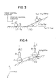
- Fig. 3 is a view showing a way of giving of the urging-force command, and illustrates an example of the case where a surface of a work 50 is profiled by the working tool 4.
- the width of the dead zone in an x-axis direction is taken large by the control computing section 17 shown in Fig. 1, to the position control, and the spring constant in a z-axis direction is brought to 0 (zero) to the force control.
- the command f r0 of the constant urging force is set in the z-axis direction by the force-command setting section 7, and is outputted directly to the force-error computing section 12.
- an z-axis component u z of the velocity command u is computed by the control computing section 17, from the error ⁇ f between the force command f ro and the force/moment f on the basis of the detecting value.
- the working tool 4 is urged against the work surface with the force command value f ro by the velocity command u z .
- an x-axis component u x of the velocity command u is computed by the control computing section 17, from the error ⁇ x between the position/posture command x r and the position/posture x on the basis of the detecting value.
- the working tool 4 is fed in the x-axis direction at the feed velocity v x on the basis of the velocity command u x .
- the embodiment is based on the knowledge described above, and the computation is effected by the gradient computing section 61, the feed-velocity computing section 62 and the urging-force computing section 63 illustrated in Fig. 1, to control the working tool 4 so as to profile the work surface with the constant urging force.
- the gradient tan ⁇ of the work surface at the point P j can approach the following equation: The above equation is computed by the gradient computing section 61.
- ⁇ t is a detecting time between the point P i and the point P j .
- the hand positions must successively be stored by the memory section 60 in terms of the constant time duration ⁇ t, and the time duration ⁇ t must be stored in the feed-velocity computing section 62.
- v xy ⁇ v x 2 + v y 2
- the new urging-force command f r obtained by the urging-force computing section 63 in this manner is sent to the force-error computing section 12 as the force command f r , and is used in obtaining the aforementioned force error ⁇ f .
- FIG. 5 A second embodiment of the invention will be described with reference to Figs. 5 and 6.
- members or elements similar to those illustrated in Figs. 1 and 2 are designated by the same reference numerals.
- a force-command correcting section 7B of a profiling control system comprises the following elements, in addition to the arrangement of the first embodiment illustrated in Fig. 2. That is, the force-command correcting section 7B comprises a memory section 70 for storing therein a feed-target position at start of the profiling operation of the working tool 4, a feed-directional vector computing section 71 for computing a feed-directional vector m from the position computed by the position computing section 14 and the feed-target position stored in the memory section 70, and a setting section 62A for setting a feed-target velocity v xyo at the start of the profiling operation of the working tool.
- a gradient computing section 72 has a function of computing the gradient tan ⁇ of the work surface from the reaction-force vector f acting upon the working tool 4, which is obtained by the force computing section 9 and the transformation section 10 shown in Fig. 1, and from the feed-directional vector m obtained by the feed-directional-vector computing section 71.
- the urging-force computing section 63 computes a new urging-force command f r from the gradient tan ⁇ of the work surface, obtained by the gradient computing section 72, the feed velocity v xy obtained by the feed-velocity computing section 62 or the feed target velocity v xyo set by the setting section 62A, and the force command f ro set in the force-command setting section 7.
- the feed target velocity v xyo set in the section 62A is also sent to the position command setting section 8, in which ⁇ v xyo is successively added to the present position command to compute a new position command at teach sampling time ⁇ .
- This computation is substantially the same as that carried out in the moving-position-command computing section 97 of the later-mentioned embodiment shown in Fig. 17, and thus the details are omitted here.
- Fig. 6 is a view showing a way of giving of the gradient tan ⁇ of the work surface in the force-command correcting section 7B of the embodiment, and illustrates a condition in which the working tool is urged against the surface of the work 50 to start the profiling operation.
- the present position computed by the position computing section 14 is brought to a point P(x p , y p , z p ), and the feed-command position of the working tool stored in the memory section 70 is brought to a point Q(x q , y q , z q ). If a feed-directional vector m , which indicates the feed direction of the working tool 4, is obtained from the point P and the point Q , m (x q - x p , y q - Y p , 0) is obtained. This computation is carried out by the feed-directional-vector computing section 71.
- a competent of the normal vector n is expressed by three components (f x , f y , f z ) of the reaction-force vector f in the x, y and z directions.
- a unit vector in the moving direction on the work surface at the point P is t
- its directional cosine is expressed by (t x , t y , t z ). Since the vector t is a contact vector of the work surface at the point P , the vector t is perpendicularly intersected with the normal-directional vector n .
- tan ⁇ l ⁇ t z / ⁇ (l ⁇ t x ) 2+ (l ⁇ t y ) 2
- l ⁇ t z -l(f x t x + f y t y )/f z (5)
- the reaction-force vector f obtained by the feed-directional- vector computing section 71 and the feed-direction vector m obtained by the transformation section 10 are used to conduct the above computation thereby obtaining the gradient tan ⁇ of the work surface in the moving direction.
- the gradient tan ⁇ of the work surface with respect to the feed direction obtained by the gradient computing section 72 in the manner described above, the command velocity v xyo set in the feed-target-velocity setting section 62A and the force command f ro set in the force-command setting section 7 are used to compute f r f ro - Cv xyo tan ⁇ , in a manner similar to the first embodiment, thereby computing the new urging-force command f r as an urging-force command. Accordingly, similarly to the first embodiment, a changing portion of the urging force occurring by the feed-target velocity v xyo is subtracted. Thus, it is possible to profile the work surface while the working tool 4 is urged with the command f ro .
- the feed-target position stored in the memory section 70 and the feed-target velocity v xyo set in the setting section 62A are used to compute a urging-force command, thereby effecting the control of the position/force.
- the position/force is controlled similarly to the first embodiment. That is, gradient computing section 72 computes the gradient tan ⁇ of the work surface with respect to the feed direction on the basis of the position data stored in the memory section 60.
- the feed-directional velocity computing section 62 computes the feed velocity v xy by the use of the position data stored in the memory section 60.
- the urging-force computing section 63 computes the urging-force command f r by the use of the gradient tan ⁇ of the work surface in the moving direction, obtained by the gradient computing section 72, the feed velocity v xy obtained by the feed-velocity computing section 62, and the force command f ro set in the force-command setting section 7.
- the position information on the profiling locus stored in the memory section 70 and the feed velocity v xyo set in the setting section 62A are used to compute the urging-force command. Accordingly, it is possible to compute the urging-force command even at the stop of the profiling operation, and it is possible to control the urging force even at the start of the profiling operation.
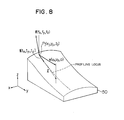
- FIG. 7 A third embodiment of the invention will be described with reference to Figs. 7 and 8.
- members or elements similar to those illustrated in Figs. 1 and 2 are designated by the same reference numerals.
- a force-command correcting section 7C of a profiling control system comprises a memory section 60 for successively storing therein the positions computed by the position computing section 14, a feed-velocity computing section 80 for computing a feed-velocity vector v of the working tool 4 in a direction perpendicular to the urging direction from the position stored in the memory section 60, a gradient computing section 81 for computing the gradient tan ⁇ of the work surface with respect to the feed direction from the direction of the reaction-force vector f acting upon the working tool 4 and computed by the force computing section 9 and the transformation section 10 and from a direction of the feed-velocity vector v obtained by the computing section 80, and an urging-force computing section 63 for computing a new urging-force command f r from the gradient tan ⁇ obtained by the computing section 81, the magnitude of the feed-velocity vector v obtained by the computing section 80 and the force command f ro set in the force-command setting section
- a condition will be considered in which the surface of the work 50 is profiled by the working tool 4.
- the position of the working tool 4 which is computed by the position computing section 14 at intervals of each optical time ⁇ t, is stored in the memory section 60.
- P j is the present position of the working tool 4
- P i is a position prior to the present position.
- ⁇ v x 2 + v y 2 (9) The mean velocity is consistent with the magnitude of the feed-velocity command v , and is the same in value as the feed velocity v xy described in the first embodiment. Accordingly, the feed velocity will be expressed below by v xy .
- the feed-velocity computing section 80 effects the computation mentioned above.
- Fig. 8 is a view showing a way of giving the gradient tan ⁇ of the work surface in the gradient computing section 81 of the embodiment.
- the present detecting position is the point P j in the same manner as Fig. 4, and the feed-velocity vector is expressed by v (v x , v y , 0) described above.
- the urging-reaction-force vector f (f x , f y , f z ) of the work surface at the point P j is a normal-directional vector.
- the unit vector in the moving direction on the work surface at the point P j is expressed by t
- l is determined such that a value at the time the unit vector t is multiplied by l and the vector l t is projected onto the x - y plane is consistent with the feed-velocity vector v .
- the component of the vector l t is expressed by (l ⁇ t x , l ⁇ t y l ⁇ t ) z .
- l ⁇ t z - l(f x t x +f y t y )/f z
- l ⁇ t x and l ⁇ t y are consistent with the feed-velocity vector v
- the equations (12) and (13) are used to rearrange the equation (11), the following equations
- f r f ro - Cv xy tan ⁇ is computed from the feed velocity v xy , the gradient tan ⁇ and the force command f ro , to obtain a new urging-force command f r .
- the working tool 4 is controlled such that the work surface is profiled with a constant urging force.
- the gradient tan ⁇ is obtained by the procedure different from that of the first embodiment, so that it is possible to obtain advantages similar to those of the first embodiment.
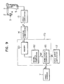
- FIG. 9 A fourth embodiment of the invention will be described with reference to Fig. 9.
- members or elements similar to those illustrated in Figs. 1 and 2 are designated by the same reference numerals.
- a force-command correcting section 7D of a profiling control system comprises a memory 60 for successively storing therein the position data of the hand position/posture x , obtained by the position computing section 14, at intervals of each constant time in accordance with movement of the hand, a moving-velocity computing section 82 for computing a moving velocity v zof of the working tool 4 in the urging direction on the basis of the position data stored in the memory section 60, and an urging-force computing section 83 for computing a new urging-force command f r from the moving velocity v zof obtained by the moving-velocity computing section 82 and the urging-force command f ro set by the force-command setting section 7.
- the new urging-force command f r obtained by the urging-force computing section 83 is outputted to the force-error computing section 12.
- the position data stored in the memory section 60 are stored at the intervals of each constant time, and its numbers are within a range which is used by the moving-velocity computing section 82.
- Fig. 4 when the work surface is profiled while the working tool 4 is urged in the z-axis direction, the present position stored in the memory section 60 is brought to a point P j (x j , y j , z j ), as mentioned previously, and a position prior to the present position is brought to a point P i (x i , y i , z i ). Then, the z-directional velocity v zof at the point P j can approach the following equation:
- ⁇ t is a time between the points P i and P j .
- the time ⁇ t is beforehand stored in the moving-velocity computing section 82.
- the moving-velocity computing section 82 effects the computation described above.
- the force occurring in the z-axis direction is computed by the use of the gradient tan ⁇ and the feed velocity v xy
- the force f of occurring in the z-axis direction is computed directly from the moving velocity v zof in the z-axis direction.
- the new urging force obtained by the urging-force computing section 83 in the manner described above is sent to the force-error computing section 12 as the force command f r , and is used for obtaining the force-error ⁇ f .
- the computation is easy as compared with the procedure which computes the gradient in the first through third embodiments.
- a further high-speed computation treatment is made possible.
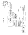
- FIG. 10 A fifth embodiment of the invention will be described with reference to Figs. 10 and 11.
- members or elements similar to those illustrated in Figs. 1 and 2 are designated by the same reference numerals.
- a profiling control system 6A is used in the following manner. That is, a velocity command u o is computed by the characteristic-compensation computing section 21 of the control computing section 17. The velocity command u o is corrected by a velocity-command correcting section 90A, to obtain a new velocity command u . The velocity command u is used in the angular-velocity computing section 23. The force command f r is sent from the force-command setting section 7 directly to the error computing section 12.
- the velocity-command correcting section 90A comprises a memory section 60 for successively storing therein the position data of the hand position/posture x obtained by the position computing section 14, in accordance with movement of the hand, a gradient computing section 61 for computing the gradient tan ⁇ of the work surface with respect to the feed direction of the working tool 4 on the basis of the position data stored in the memory section 60, and a feed-velocity computing section 62 for computing a feed velocity v xy of the working tool 4, from the position obtained by the position computing section 14 and its detecting time ⁇ t.
- the velocity-command correcting section 90A comprises a correcting-velocity computing section 90 for computing a velocity correcting value v zc in the urging direction from the gradient tan ⁇ obtained by the gradient computing section 61 and the feed velocity v xy obtained by the feed-velocity computing section 62, and an adder 91 for adding the velocity correcting value v zc obtained by the computing section 90 to the z-axis component u zo of the velocity command u o obtained by the control computing section 17, to obtain a new velocity command u thereby outputting the velocity command u to the angular-velocity computing section 23.
- the feed velocity v xy in a direction parallel to the x - y plane is computed from the position information of the two points P j and P i , similarly to the first embodiment.
- the force command f r is not corrected, but the velocity command u o computed by the control computing section 17 is corrected.
- FIG. 12 A sixth embodiment of the invention will be described with reference to Fig. 12.
- members or components similar to those illustrated in Figs. 5, 10 and 11 are designated by the same reference numerals.
- the computing means of the gradient tan ⁇ in the velocity-command correcting section of the fifth embodiment is replaced by the computing means of the gradient tan ⁇ in the second embodiment illustrated in Fig. 5. That is, as shown in Fig. 12, similarly to the force-command correcting section 7B of the embodiment shown in Fig.
- a velocity-command correcting section 90B comprises a memory section 60, a feed-velocity computing section 62, a memory section 70 for storing therein the feed-target position, a feed-directional vector computing section 71 for computing a feed-directional vector m from the position computed by the position computing section 14 and the feed-target position stored in the memory section 70, a gradient computing section 72 for computing a gradient tan ⁇ of the work surface from the reaction-force vector f acting upon the working tool 4, computed by the force computing section 9 and the transformation section 10 and a feed-directional vector m obtained by the computing section 71, and a setting section 62A for setting a feed-target velocity v xyo .
- the velocity-command correcting section 90B comprises a correcting-velocity computing section 90 for computing a velocity command v zc in the urging direction from the gradient tan ⁇ obtained by the gradient computing section 61 and the feed velocity v xy obtained by the feed-velocity computing section 62 or the feed-target velocity v xyo set in the setting section 62A, and an adder 91 for adding the velocity correcting value v zc obtained by the computing section 90 to the z-axis component u zo of the velocity command u o obtained by the control computing section 17 to obtain a new velocity command u , thereby outputting the new velocity command u to the angular-velocity computing section 23.
- the computing contents of the gradient computing section 72 which compute the gradient tan ⁇ of the work surface in the moving direction from the reaction-force vector f and the feed-direction vector m , are the same as those of the second embodiment shown in Fig. 5, and the computing contents of the correcting-velocity computing section 90 are the same as those of the fifth embodiment illustrated in Fig. 11.
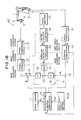
- FIG. 13 A seventh embodiment of the invention will be described with reference to Fig. 13.
- members or components similar to those illustrated in Figs. 7, 10 and 11 are designated by the same reference numerals.
- the computing means of the gradient tan ⁇ in the velocity-command correcting section of the fifth embodiment is replaced by the computing means of the gradient tan ⁇ in the third embodiment shown in Fig. 7. That is, as illustrated in Fig. 13, similarly to the force command correcting section 7C of the embodiment shown in Fig.
- a velocity-command correcting section 90C of the embodiment comprises a memory section 60 for successively storing therein the positions computed by the position computing section 14, a feed-velocity computing section 80 for computing a feed-velocity vector v of the working tool 4 from the positions stored in the memory section 60, and a gradient computing section 81 for computing the gradient tan ⁇ of the work surface from the direction of the reaction-force vector f acting upon the working tool 4, computed by the force computing section 9 and the transformation section 10 and from the direction of the feed-velocity vector v .
- the velocity-command correcting section 90C comprises a correcting-velocity computing section 90 for computing the velocity correcting value v zc in the urging direction from the gradient tan ⁇ obtained by the gradient computing section 81 and the magnitude of the feed-velocity vector v obtained by the feed-velocity computing section 80, and an adder 91 for adding the velocity correcting value v zc obtained by the computing section 90 to the z-axis component u zo of the velocity command u o obtained by the control computing section 17, to obtain a new velocity command u thereby outputting the new velocity command u to the angular-velocity computing section 23.
- the computing contents conducted by the feed-velocity computing section 80 and the gradient computing section 81 are the same as those of the third embodiment shown in Fig. 7.
- the computing contents effected by the correcting-velocity computing section 90 are the same as those of the fifth embodiment illustrated in Fig. 11.
- the velocity command u o computed by the control computing section 17 similarly to the fifth embodiment is corrected by the velocity correcting value v zc , to control the working tool 4 so as to profile the work surface while the working tool 4 is urged with the force of the command f r .
- FIG. 14 An eighth embodiment of the invention will be described with reference to Fig. 14.
- members or components similar to those illustrated in Figs. 9, 10 and 11 are designated by the same reference numerals.
- the computing means of the velocity correcting value v zc in the velocity-command correcting section according to the fifth embodiment is replaced by the means for computing the moving velocity v zof of the working tool in the urging direction in the fourth embodiment shown in Fig. 9. That is, as shown in Fig.
- a velocity-command correcting section 90D comprises a memory 60 for successively storing the position data of the hand position/posture x obtained by the position computing section 14, at intervals of each constant time in accordance with movement of the hand, a moving-velocity computing section 82 for computing a moving velocity v zof of the working tool 4 in the urging direction on the basis of the position data stored in the memory section 60, to bring the moving velocity v zof to a velocity correcting value v zc , and an adder 91 for adding the velocity correcting value v zc obtained by the computing section 82 to the z-axis component u zo of the velocity command u o obtained by the control computing section 17, to obtain a new velocity command u thereby outputting the velocity command u to the angular-velocity computing section 23.
- the computing contents conducted by the moving-velocity computing section 82 are the same as those of the fourth embodiment illustrated in Fig. 9.
- the velocity command u o computed by the control computing section 17 is corrected by the velocity correcting value v zc , similarly to the fifth embodiment, thereby controlling the working tool 4 so as to profile the work surface while the working tool 4 is urged with the command f r .
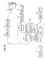
- FIG. 15 A ninth embodiment of the invention will be described with reference to Fig. 15.
- members or components similar to those illustrated in Figs. 1, 2 and 5 are designated by the same reference numerals.
- the actual feeding velocity v xy of the working tool 4 is computed in the feed-velocity computing section 62, from the position obtained by the position computing section 14, and the feed velocity v xy is used to compute the urging-force command f r by the computing section 63.
- the feed-velocity computing section 62 is not used, but the feed-target-velocity setting section 62A is used.
- the function of the feed-target-velocity setting section 62A is the same as that of the feed-target-velocity setting section 62A of the second embodiment.
- a new urging-force command f r is computed from the gradient tan ⁇ obtained by the computing section 61, the feed-target velocity v xyo set by the setting section 62A and the urging-force command f ro set by the force-command setting section 7.
- the feed-target-velocity setting section 62A can likewise be used in substitution for the moving-velocity computing section 62.
- FIG. 16 A tenth embodiment of the invention will be described with reference to Figs. 16 and 17.
- members or components similar to those shown in Figs. 1 and 2 are designated by the same reference numerals.
- a profiling control system 6C comprises a position/force- command computing section 7F which stores therein the gradient of the work surface and the moving locus of the working tool beforehand as taught data.
- the command computing section 7F the force/moment command f r and the moving-position command x r are computed at playback from the taught data stored, the urging-force command f ro of the working tool 4 beforehand set in the setting section 7, and the feed target velocity v xyo of the working tool 4 set beforehand in the feed-velocity setting section 62A.
- the moving-position command x r and the force/moment command f r computed by the computing section 7F are sent respectively to the position-error computing section 15 and the force-error computing section 12, to obtain the force error ⁇ f and the position error ⁇ X .
- Other constructions of the profiling control system 6C are the same as those of the first embodiment.
- the position/force-command computing section 7F comprises a memory section 60 for successively storing therein the position data of the hand position/posture x obtained by the position computing section 14, in accordance with movement of the hand, a gradient computing section 61 for computing a gradient tan ⁇ of the work surface with respect to the feed direction of the working tool on the basis of the position data of the position/posture x obtained by the position computing section 14, a gradient memory section 95 for successively storing the gradient tan ⁇ obtained by the gradient computing section 61 in accordance with movement of the working tool 4, an urging-force computing section 63 for computing a new urging-force command f r from the gradient tan ⁇ stored in the memory section 95, the feed target velocity v xyo set in the feed-target velocity setting section 62A and the urging-force command f ro set in the force-command setting section 7, and a moving-position-command computing section 97 for computing a moving-position command x r at
- the position data x of the working tool 4, obtained by the position computing section 14, are successively sent to the gradient computing section 61.
- the gradient tan ⁇ of the work surface in a direction in which the working tool 4 between adjacent two points moves is computed from the position of the two points. Results of the computation are successively stored in the memory section 95.
- the computation contents of the gradient computing section 61 are the same as those of the gradient computing section 61 in the first embodiment.
- the positions x of the working tool 4 obtained by the position computing section 14 are successively stored in the memory section 60 in accordance with movement of the hand.
- the position data stored at this time are stored at intervals of optional time or at intervals of moving distance. Numbers of the position data are within a range which is used in the moving-position-command computing section 97.
- the moving-position command x r is computed such that the working tool 4 moves through the position stored in the memory section 60 with the feed target velocity v xyo is set in the feed target velocity setting section 62A.
- a moving vector l xy on the x - y plane is obtained from the position data x i of number i and the position data x i+1 of number i +1 stored in the memory section 60. Further, components of the l xy in the x-axis and y-axis directions are brought respectively to l x and l y .
- the moving amount per one sampling time is added to the present command at intervals of each sample.
- the urging-force command f r and the moving-position command x r are respectively computed and given at playback, whereby it is possible to profile the work surface while the working tool is urged with the force of the command f .
- the computed gradient tan ⁇ of the work surface is once stored as the taught data, and the urging-force command is computed by the use of the taught data. Accordingly, the computing amount at control decreases less than that of the aforementioned embodiment in which the urging-force command is computed while computing also the gradient tan ⁇ of the work surface at real time. Thus, the profiling control superior to response ability is made possible.
- the feed velocity v xy is computed from the position data of the working tool, however, the value obtained by averaging the velocity command u may be used in place of the feed velocity v xy .
- the invention is likewise applicable to a case where the work is gripped by the robot, and the working tool is fixed to the base, to conduct the profiling operation.
Landscapes
- Engineering & Computer Science (AREA)
- General Physics & Mathematics (AREA)
- Theoretical Computer Science (AREA)
- Human Computer Interaction (AREA)
- Manufacturing & Machinery (AREA)
- Physics & Mathematics (AREA)
- Computing Systems (AREA)
- Automation & Control Theory (AREA)
- Robotics (AREA)
- Mechanical Engineering (AREA)
- Manipulator (AREA)
- Control Of Position Or Direction (AREA)
- Machine Tool Copy Controls (AREA)
Applications Claiming Priority (4)
| Application Number | Priority Date | Filing Date | Title |
|---|---|---|---|
| JP258598/88 | 1988-10-14 | ||
| JP25859888 | 1988-10-14 | ||
| JP26795288 | 1988-10-24 | ||
| JP267952/88 | 1988-10-24 |
Publications (3)
| Publication Number | Publication Date |
|---|---|
| EP0364057A2 true EP0364057A2 (de) | 1990-04-18 |
| EP0364057A3 EP0364057A3 (de) | 1991-01-02 |
| EP0364057B1 EP0364057B1 (de) | 1995-05-17 |
Family
ID=26543749
Family Applications (1)
| Application Number | Title | Priority Date | Filing Date |
|---|---|---|---|
| EP89202594A Expired - Lifetime EP0364057B1 (de) | 1988-10-14 | 1989-10-13 | Profilsteuersystem für eine gegebene gekrümmte Fläche |
Country Status (3)
| Country | Link |
|---|---|
| US (1) | US4987356A (de) |
| EP (1) | EP0364057B1 (de) |
| DE (1) | DE68922684T2 (de) |
Cited By (9)
| Publication number | Priority date | Publication date | Assignee | Title |
|---|---|---|---|---|
| EP0479648A1 (de) * | 1990-10-02 | 1992-04-08 | Automobiles Peugeot | Verfahren zur automatischen Regelung der Schneidkraft die von einem Industrieroboter auf ein Werkzeug ausgeübt wird, z.B. zum Abgraten von Kämmen auf einem Werkstück |
| FR2682905A1 (fr) * | 1991-10-28 | 1993-04-30 | Commissariat Energie Atomique | Procede de generation de trajectoire pour un systeme robotise. |
| EP0766159A1 (de) * | 1995-09-28 | 1997-04-02 | Toyota Jidosha Kabushiki Kaisha | Folgesteuerungsverfahren und -gerät |
| EP0849654A3 (de) * | 1996-12-21 | 1999-09-22 | Carl Zeiss | Verfahren zur Steuerung von Koordinatenmessgeräten und Koordinatenmessgerät |
| WO2006109094A1 (en) * | 2005-04-13 | 2006-10-19 | Renishaw Plc | Method of error correction |
| EP1628177A3 (de) * | 2004-08-17 | 2008-11-12 | Fanuc Ltd | Feinbearbeitungsmaschine zum Entgraten |
| US8006398B2 (en) | 2005-04-26 | 2011-08-30 | Renishaw Plc | Method for scanning the surface of a workpiece |
| EP2458320A1 (de) * | 2010-11-24 | 2012-05-30 | Canon Kabushiki Kaisha | Vorrichtung zur Messung von Formen des Berührungstyps |
| EP2471617A4 (de) * | 2009-08-27 | 2015-06-10 | Ntn Toyo Bearing Co Ltd | Vorrichtung zur erkennung der werkzeugspitzenposition eines ferngesteuerten stellgliedes |
Families Citing this family (15)
| Publication number | Priority date | Publication date | Assignee | Title |
|---|---|---|---|---|
| EP0398704B1 (de) * | 1989-05-17 | 1996-08-14 | Fujitsu Limited | Profilsteuerungssystem für Roboter |
| US5311109A (en) * | 1992-03-31 | 1994-05-10 | Honda Giken Kogyo Kabushiki Kaisha | Locomotion control system for legged mobile robot |
| US5508596A (en) * | 1993-10-07 | 1996-04-16 | Omax Corporation | Motion control with precomputation |
| SE9900123L (sv) * | 1999-01-15 | 2000-07-16 | Abb Ab | Metod för robot |
| US6104712A (en) * | 1999-02-22 | 2000-08-15 | Robert; Bruno G. | Wireless communication network including plural migratory access nodes |
| US6456901B1 (en) * | 2001-04-20 | 2002-09-24 | Univ Michigan | Hybrid robot motion task level control system |
| US8419717B2 (en) * | 2006-06-13 | 2013-04-16 | Intuitive Surgical Operations, Inc. | Control system configured to compensate for non-ideal actuator-to-joint linkage characteristics in a medical robotic system |
| DE102006049957A1 (de) * | 2006-10-19 | 2008-04-24 | Abb Ag | System und Verfahren zur Kalibrierung einer Handhabungsvorrichtung |
| CN101952087B (zh) * | 2008-02-06 | 2013-01-16 | 松下电器产业株式会社 | 机器人、机器人的控制装置及控制方法 |
| US9613180B1 (en) * | 2011-06-02 | 2017-04-04 | Hrl Laboratories, Llc | Robotic control device and method for manipulating a hand-held tool |
| FR3044574B1 (fr) * | 2015-12-03 | 2019-06-14 | Institut Maupertuis | Robot de soudage par friction malaxage |
| US10859997B1 (en) | 2017-12-04 | 2020-12-08 | Omax Corporation | Numerically controlled machining |
| US11554461B1 (en) | 2018-02-13 | 2023-01-17 | Omax Corporation | Articulating apparatus of a waterjet system and related technology |
| JP7451940B2 (ja) * | 2019-10-31 | 2024-03-19 | セイコーエプソン株式会社 | 制御方法および算出装置 |
| US12051316B2 (en) | 2019-12-18 | 2024-07-30 | Hypertherm, Inc. | Liquid jet cutting head sensor systems and methods |
Family Cites Families (4)
| Publication number | Priority date | Publication date | Assignee | Title |
|---|---|---|---|---|
| JPS6179549A (ja) * | 1984-09-28 | 1986-04-23 | Takaaki Nagao | 曲面加工装置 |
| JPS61269710A (ja) * | 1985-05-24 | 1986-11-29 | Mitsubishi Heavy Ind Ltd | 倣い軌跡のデイジタイジング方法 |
| US4719578A (en) * | 1985-12-09 | 1988-01-12 | Mitsubishi Jukogyo Kabushiki Kaisha | Profiling control apparatus and control method thereof |
| US4702652A (en) * | 1985-12-30 | 1987-10-27 | Mitsubishi Jukogyo Kabushiki Kaisha | Advanced memory type profiling control method for a machine tool |
-
1989
- 1989-10-13 US US07/421,371 patent/US4987356A/en not_active Expired - Lifetime
- 1989-10-13 DE DE68922684T patent/DE68922684T2/de not_active Expired - Fee Related
- 1989-10-13 EP EP89202594A patent/EP0364057B1/de not_active Expired - Lifetime
Non-Patent Citations (4)
| Title |
|---|
| IEEE JOURNAL OF ROBOTICS AND AUTOMATION. vol. 4, no. 3, June 1988, NEW YORK US pages 324 - 333; H. KAZEROONI: "DIRECT-DRIVE ACTIVE COMPLIANT END EFFECTOR" * |
| INTERNATIONAL JOURNAL OF ROBOTICS RESEARCH vol. 6, no. 1, 1987, CAMBRIDGE MA US pages 3 - 14; Daniel E. Whitney: "HISTORICAL PERSPECTIVE AND STATE OF THE ART IN ROBOT FORCE CONTROL" * |
| PROCEEDINGS 1987 IEEE ROBOTICS AND AUTOMATION CONFERENCE vol. 3, April 1987, USA pages 2055 - 2060; YOUCEF-TOUMI AND LI: "FORCE CONTROL OF DIRECT-DRIVE MANIPULATORS FOR SURFACE FOLLOWING" * |
| PROCEEDINGS 1988 AMERICAN CONTROL CONFERENCE vol. 1, 15 June 1988, USA pages 108 - 103; KAZEROONI AND HER: "Robotic Deburring of Parts with Unknown Geometry" * |
Cited By (15)
| Publication number | Priority date | Publication date | Assignee | Title |
|---|---|---|---|---|
| EP0479648A1 (de) * | 1990-10-02 | 1992-04-08 | Automobiles Peugeot | Verfahren zur automatischen Regelung der Schneidkraft die von einem Industrieroboter auf ein Werkzeug ausgeübt wird, z.B. zum Abgraten von Kämmen auf einem Werkstück |
| FR2682905A1 (fr) * | 1991-10-28 | 1993-04-30 | Commissariat Energie Atomique | Procede de generation de trajectoire pour un systeme robotise. |
| EP0544346A1 (de) * | 1991-10-28 | 1993-06-02 | Commissariat A L'energie Atomique | Verfahren zur Erzeugung einer Bewegungsbahn für ein robotisiertes System |
| EP0766159A1 (de) * | 1995-09-28 | 1997-04-02 | Toyota Jidosha Kabushiki Kaisha | Folgesteuerungsverfahren und -gerät |
| US5952807A (en) * | 1995-09-28 | 1999-09-14 | Toyota Jidosha Kabushiki Kaisha | Tracing control method and apparatus |
| EP0849654A3 (de) * | 1996-12-21 | 1999-09-22 | Carl Zeiss | Verfahren zur Steuerung von Koordinatenmessgeräten und Koordinatenmessgerät |
| EP1628177A3 (de) * | 2004-08-17 | 2008-11-12 | Fanuc Ltd | Feinbearbeitungsmaschine zum Entgraten |
| WO2006109094A1 (en) * | 2005-04-13 | 2006-10-19 | Renishaw Plc | Method of error correction |
| US7286949B2 (en) | 2005-04-13 | 2007-10-23 | Renishaw Plc | Method of error correction |
| US8006398B2 (en) | 2005-04-26 | 2011-08-30 | Renishaw Plc | Method for scanning the surface of a workpiece |
| US8978261B2 (en) | 2005-04-26 | 2015-03-17 | Renishaw Plc | Probe head for scanning the surface of a workpiece |
| EP2471617A4 (de) * | 2009-08-27 | 2015-06-10 | Ntn Toyo Bearing Co Ltd | Vorrichtung zur erkennung der werkzeugspitzenposition eines ferngesteuerten stellgliedes |
| US9126270B2 (en) | 2009-08-27 | 2015-09-08 | Ntn Corporation | Device for detecting tool tip position of remote-controlled actuator |
| EP2458320A1 (de) * | 2010-11-24 | 2012-05-30 | Canon Kabushiki Kaisha | Vorrichtung zur Messung von Formen des Berührungstyps |
| US9016106B2 (en) | 2010-11-24 | 2015-04-28 | Canon Kabushiki Kaisha | Contact type shape measuring apparatus |
Also Published As
| Publication number | Publication date |
|---|---|
| EP0364057B1 (de) | 1995-05-17 |
| EP0364057A3 (de) | 1991-01-02 |
| DE68922684T2 (de) | 1995-10-19 |
| JPH02198748A (ja) | 1990-08-07 |
| DE68922684D1 (de) | 1995-06-22 |
| US4987356A (en) | 1991-01-22 |
Similar Documents
| Publication | Publication Date | Title |
|---|---|---|
| EP0364057A2 (de) | Profilsteuersystem für eine gegebene gekrümmte Fläche | |
| US5129044A (en) | Position/force controlling apparatus for working machine with multiple of degrees of freedom | |
| EP0349291B1 (de) | Roboter mit Werkzeugsteuerung für Verschiebungsfolge | |
| US4621332A (en) | Method and apparatus for controlling a robot utilizing force, position, velocity, spring constant, mass coefficient, and viscosity coefficient | |
| Piepmeier et al. | Uncalibrated eye-in-hand visual servoing | |
| US8380352B2 (en) | Robot system | |
| Nelson et al. | Increasing the tracking region of an eye-in-hand system by singularity and joint limit avoidance | |
| Carelli et al. | Algorithms for stable control of mobile robots with obstacle avoidance | |
| Lange et al. | Predictive vision based control of high speed industrial robot paths | |
| JP2791030B2 (ja) | 多自由度作業機械の曲面倣い制御装置 | |
| JP2552279B2 (ja) | ロボツトの姿勢制御方法 | |
| JPH06332535A (ja) | ロボットの制御装置 | |
| JP3206775B2 (ja) | 加工・組立装置の倣い制御方法および倣い制御装置 | |
| JP2718687B2 (ja) | 多自由度作業機械の位置と力の制御装置 | |
| JP2594546B2 (ja) | ロボツトの仮想内部モデルに基づく制御方法 | |
| JP2610443B2 (ja) | ロボットの姿勢制御方法 | |
| Farías et al. | Influence of parallel kinematic machine dimensional tolerances on the estimation of payload inertia | |
| JP3001211B2 (ja) | 任意曲面の倣い制御装置 | |
| Maniere et al. | Robotic contour following based on visual servoing | |
| JPH0731536B2 (ja) | 教示デ−タ補正ロボツト | |
| Mudge et al. | Unifying robot arm control | |
| JP3196145B2 (ja) | 加工・組立装置における接触点および接触法線検出法 | |
| KR0155281B1 (ko) | 다관절 로보트의 직선보간방법 | |
| Lin | Identification of a class of nonlinear deterministic systems with application to manipulators | |
| JPH0713642A (ja) | マニピュレータのコンプライアンス制御装置 |
Legal Events
| Date | Code | Title | Description |
|---|---|---|---|
| PUAI | Public reference made under article 153(3) epc to a published international application that has entered the european phase |
Free format text: ORIGINAL CODE: 0009012 |
|
| AK | Designated contracting states |
Kind code of ref document: A2 Designated state(s): DE FR GB IT SE |
|
| PUAL | Search report despatched |
Free format text: ORIGINAL CODE: 0009013 |
|
| AK | Designated contracting states |
Kind code of ref document: A3 Designated state(s): DE FR GB IT SE |
|
| 17P | Request for examination filed |
Effective date: 19910502 |
|
| 17Q | First examination report despatched |
Effective date: 19930817 |
|
| GRAA | (expected) grant |
Free format text: ORIGINAL CODE: 0009210 |
|
| AK | Designated contracting states |
Kind code of ref document: B1 Designated state(s): DE FR GB IT SE |
|
| PG25 | Lapsed in a contracting state [announced via postgrant information from national office to epo] |
Ref country code: IT Free format text: LAPSE BECAUSE OF FAILURE TO SUBMIT A TRANSLATION OF THE DESCRIPTION OR TO PAY THE FEE WITHIN THE PRE;WARNING: LAPSES OF ITALIAN PATENTS WITH EFFECTIVE DATE BEFORE 2007 MAY HAVE OCCURRED AT ANY TIME BEFORE 2007. THE CORRECT EFFECTIVE DATE MAY BE DIFFERENT FROM THE ONE RECORDED.SCRIBED TIME-LIMIT Effective date: 19950517 Ref country code: FR Effective date: 19950517 |
|
| REF | Corresponds to: |
Ref document number: 68922684 Country of ref document: DE Date of ref document: 19950622 |
|
| PG25 | Lapsed in a contracting state [announced via postgrant information from national office to epo] |
Ref country code: SE Effective date: 19950817 |
|
| EN | Fr: translation not filed | ||
| PG25 | Lapsed in a contracting state [announced via postgrant information from national office to epo] |
Ref country code: GB Effective date: 19951013 |
|
| PLBE | No opposition filed within time limit |
Free format text: ORIGINAL CODE: 0009261 |
|
| STAA | Information on the status of an ep patent application or granted ep patent |
Free format text: STATUS: NO OPPOSITION FILED WITHIN TIME LIMIT |
|
| 26N | No opposition filed | ||
| GBPC | Gb: european patent ceased through non-payment of renewal fee |
Effective date: 19951013 |
|
| PGFP | Annual fee paid to national office [announced via postgrant information from national office to epo] |
Ref country code: DE Payment date: 20041007 Year of fee payment: 16 |
|
| PG25 | Lapsed in a contracting state [announced via postgrant information from national office to epo] |
Ref country code: DE Free format text: LAPSE BECAUSE OF NON-PAYMENT OF DUE FEES Effective date: 20060503 |