EP0364062A2 - Système de protection pour véhicule - Google Patents
Système de protection pour véhicule Download PDFInfo
- Publication number
- EP0364062A2 EP0364062A2 EP89301251A EP89301251A EP0364062A2 EP 0364062 A2 EP0364062 A2 EP 0364062A2 EP 89301251 A EP89301251 A EP 89301251A EP 89301251 A EP89301251 A EP 89301251A EP 0364062 A2 EP0364062 A2 EP 0364062A2
- Authority
- EP
- European Patent Office
- Prior art keywords
- vehicle
- protection system
- track
- flexible
- cover
- Prior art date
- Legal status (The legal status is an assumption and is not a legal conclusion. Google has not performed a legal analysis and makes no representation as to the accuracy of the status listed.)
- Ceased
Links
Images


Classifications
-
- B—PERFORMING OPERATIONS; TRANSPORTING
- B60—VEHICLES IN GENERAL
- B60J—WINDOWS, WINDSCREENS, NON-FIXED ROOFS, DOORS, OR SIMILAR DEVICES FOR VEHICLES; REMOVABLE EXTERNAL PROTECTIVE COVERINGS SPECIALLY ADAPTED FOR VEHICLES
- B60J11/00—Removable external protective coverings specially adapted for vehicles or parts of vehicles, e.g. parking covers
- B60J11/04—Removable external protective coverings specially adapted for vehicles or parts of vehicles, e.g. parking covers for covering at least the roof of the vehicle, e.g. for covering the whole vehicle
-
- B—PERFORMING OPERATIONS; TRANSPORTING
- B60—VEHICLES IN GENERAL
- B60J—WINDOWS, WINDSCREENS, NON-FIXED ROOFS, DOORS, OR SIMILAR DEVICES FOR VEHICLES; REMOVABLE EXTERNAL PROTECTIVE COVERINGS SPECIALLY ADAPTED FOR VEHICLES
- B60J11/00—Removable external protective coverings specially adapted for vehicles or parts of vehicles, e.g. parking covers
- B60J11/06—Removable external protective coverings specially adapted for vehicles or parts of vehicles, e.g. parking covers for covering only specific parts of the vehicle, e.g. for doors
-
- B—PERFORMING OPERATIONS; TRANSPORTING
- B60—VEHICLES IN GENERAL
- B60R—VEHICLES, VEHICLE FITTINGS, OR VEHICLE PARTS, NOT OTHERWISE PROVIDED FOR
- B60R13/00—Elements for body-finishing, identifying, or decorating; Arrangements or adaptations for advertising purposes
- B60R13/04—External Ornamental or guard strips; Ornamental inscriptive devices thereon
-
- B—PERFORMING OPERATIONS; TRANSPORTING
- B60—VEHICLES IN GENERAL
- B60R—VEHICLES, VEHICLE FITTINGS, OR VEHICLE PARTS, NOT OTHERWISE PROVIDED FOR
- B60R25/00—Fittings or systems for preventing or indicating unauthorised use or theft of vehicles
Definitions
- the field of the present invention is mechanical guard systems for protecting a vehicle.
- One such system for protecting a vehicle includes fixed horizontal trim and bumper work designed to provide a tough outer profile on the vehicle.
- such a system tends to be self-defeating because other vehicles have similar devices which become the first element to contact the adjacent car when the door is opened, again resulting in chips and scratches. Further, such devices are frequently incompatible with the overall design of the vehicle.
- the present invention is directed to a system for protecting vehicles from vandalism, attempted entry and impact when the vehicle is not in use.
- the protection system contemplates the employment of protective elements which can be positioned to cover or guard portions of the vehicle.
- the protection system provides a window and top cover which, when received by side bars on the vehicle, is held in place.
- the cover may be of entry resistant, semiflexible material with impact resistent members to protect the windows.
- a track on the vehicle cooperates with a cable extending therealong to mount and control a protection member.
- the protection member is thereby capable of moving up and down on the side of the vehicle to provide protection and to prevent the doors from being opened when the vehicle is not in use.
- Such members may be used to anchor and lock a window and top cover to a vehicle.
- a further aspect of the present invention contemplates a locking latch which may be actuated to extend between the door and door jam of the automobile to securely lock the door against entry.
- the flexible element associated with the track may be employed to actuate the latch.
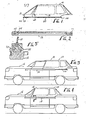
- FIG. 1 illustrates a cover 10.
- a protection member 12 shown to be a bar, is associated with the cover 10 to hold the cover 10 in place. The operation of the bar 12 will be more fully discussed below.
- the cover 10 is designed to fit relatively closely to a given window and top construction of a vehicle such as the automobile 14 illustrated in Figures 3 and 4. In this instance, the cover 10 is positioned from behind onto the bars 12 which are in turn located on either side of the vehicle 14. It can be seen that the cover 10 is of flexible material. However, it is contemplated that the cover 10 be of a very tough plastic or include imbedded metal filaments to resist cutting and tearing.
- the cover 10 conveniently incorporates a front flap 16 which is integrally associated at one end with the cover 10 and which can be drawn across the windshield of the vehicle to complete the covering of the window area of the vehicle. If it is desired to have the cover 10 very rigid, a hinge or weakened portion 17 may be employed to allow placement in a trunk.
- the cover 10 includes stiff, impact resistent panels 18 designed to cover over the window area on the vehicle for which the cover 10 has been constructed. Also included as part of the cover 10 is a rod 20 extending along either side of the cover 10 and a rod 22 extending along one edge of the flap 16.
- the rod 20 includes an interlocking head cooperating with an undercut channel 24 located in the bar 12. As the rod 20 is of substantially rigid material, only flexing along its length, it cannot be pulled easily from the undercut channel 24. The same is true of the rod 22.
- Each of the rods 20 and 22 include a lock 25 and 26, respectively. These locks 25 and 26 cooperate with locking holes 27 and 28, respectively, in the bar 12.
- the locks may be located at any convenient point and typically incorporate keys for the operation thereof.
- the bar 12 can be employed without the cover as illustrated in Figures 13 and 14.
- a drive mechanism is illustrated for placing and removing the rods 20 in the bars 12.
- a chain or cable 29 is arranged about two sprockets or rollers 30 and 31 at either end of the bar 12.
- a cavity 32 extends along the bar 12 to receive the chain 29.
- One or both of the sprockets or rollers 30 and 31 includes a means for rotating and driving the system.
- a hexagonal hole 33 is illustrated in sprocket 31.
- a crank 34 may be used to drive the chain. Electrical power may also be used.
- the rod 20 includes a tooth 35 which engages the chain 29.
- the tooth may form part of the locking mechanism if desired.
- the tooth 35 extends downwardly from the bottom of the rod 20 so as to engage the chain 29 between links.
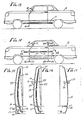
- the bar 12 is shown in a lowered position in Figure 13 and in a raised position in Figure 14. In the lowered position, the bar 12 does not interfere with the door of the vehicle 14. In the upper position, the bar 12 protects the side of the vehicle and also prevents the door from being opened. It may be noted in Figure 11 that the bar 12 is positioned on the vehicle where the vehicle is subject to the greatest possibility of impact from adjacent car doors and the like. The bar 12 is also spaced outwardly from the vehicle a small distance. This provides added protection to stop any door even before a protruding guard on the offending door can contact the side of the protected vehicle.
- the forward body panel and structure of the vehicle is shown to include a curved forward fender 36 and a lower panel 37.
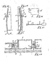
- Fixed on the fender panel 36 is a track 38.
- the track 38 is illustrated to be divided into two portions, a first upper portion and a second lower portion. The upper portion down to approximately the bottom edge of the fender panel 34 is curved so as to remain the same distance away from the fender panel 36. At the lower second portion, the track 38 curves inwardly away from the lower panel 37.
- the track is illustrated in cross section in Figure 28 and is shown to be a channel with inwardly extending flanges 40 and 44.
- the resulting structure includes an elongate passage area to operate as a semienclosed track.
- the mounting bracket 46 is shown to include a first head 48 which resides within the cavity defined in the track 38.
- the flanges 40 and 44 cooperate with the head 48 of the mounting bracket 46 to define interlocking surfaces for retaining the bracket 46 in the track 38 such that it can slide vertically therein.
- the mounting bracket 46 also includes an extended portion 50 which extends outwardly of the vehicle.
- Controlling the location of the mounting bracket 46 is a flexible, elongate element 52.
- This element is preferably in the form of a cable which extends through the track 38 and is fixed to the head 48 of the bracket 46.
- Multiple drive systems are illustrated.
- the cable and drive system of Figure 20 is generally preferred.
- Figures 15 and 16 illustrate a continuous loop of cable 52.
- This cable 52 is threaded over a pulley 54 above the track 38 and a shaft 56 below the track 38.
- movement of the cable 52 will result in movement of the bracket 46, the displacement of which is illustrated in Figures 13 and 14.
- the shaft 56 is part of a drive means for actuating the system. Illustrated in Figure 14 is the shaft 56 associated with a motor 58. Activation of the motor 58 drives the shaft 56 and in turn the cable 52. Limit switches may conventionally be employed to limit the operation of the system between two extreme positions. A detail of the motor 58 and the cables 52 on the shaft 56 is illustrated in Figure 27.
- the arrangement of the shaft 56 and motor 58 may be determined by the available room and construction of the vehicle. For example, shafts 56 may extend down the lower panels 36 on either side of the vehicle. Alternatively, a center shaft 56 may be employed to operate both sides of the vehicle. As a further alternative, one or two shafts may extend transversely of the vehicle to cooperate with cables in a similar manner.
- a second track 60 is illustrated in Figures 25 and 28.
- the track 60 can be seen in cross section in its placement as cooperating with a mounting bracket 62.
- the mounting bracket 62 is shown to be straight rather than bent, as is the mounting bracket 46, to accommodate the difference in placement between the tracks 38 and 60.
- a flexible, elongate element in the form of a cable 64 is associated with the bracket 62 to run through the track 60.
- the protection member 12 which is fixed to each of the brackets.
- the protection member 12 is shown to extend beyond the brackets.
- the brackets are of sufficient length such that the bar 12 is displaced outwardly away from the body panel of the vehicle when in the upper position and yet drawn much closer to the body panel in the lower, stored position.
- the bar 12 is preferably of structural material in order that it might not easily bend upon impact or be torn off by an intruder.
- a reflector 65 is shown in the bar 12 of Figure 26 on the outer side thereof. This is an aesthetic and safety option.
- a length of cable 66 is positioned in the track 38.
- the track 38 provides sufficient lateral constraint such that the cable 66, when in the track 38, is able to push as well as pull the protection member 12.
- the cable 66 is provided with a ridge 68 wrapped about the cable 66 to cooperate with a toothed sprocket 70.
- the toothed sprocket 70 is driven by a motor 72 through its shaft 74.
- An additional guide 76 constrains the cable 66 in engagement with the sprocket 70.
- a second cable 66 is similarly arranged on the other side of the sprocket 70 which is employed to drive a second bracket 46 or 62.
- FIG 19 One such arrangement is illustrated in Figure 19 where a single shaft 74 is driven by a motor 72 to drive four such cables 66.
- a crank 78 may be employed as an emergency mechanism to replace the motor 72 in the event of a power failure in the vehicle.
- a second battery can be employed with an appropriate bypass switch to operate the side protection members in the event of power failure of the vehicle.
- Figure 23 illustrates a drive using an automobile radio antenna type drive.
- a case 100 contains a shaft 102 which is motor driven.
- the cable 104 is wound in the case 100 and attached to the shaft 102. By rotation of the shaft, the cable 104 may be driven from or into a track 38.
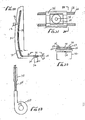
- a latch 110 is shown associated with the bracket 62 to move up and down with the protection member 12.
- the latch 110 rides within slits 112 and 114 located in the door and rear fender body panel of the vehicle. This extension of the latch 110 between the door and door jam prevents one from opening the door with the protection system in place.
- the slits 112 and 114 extend downwardly into the lower body panel in order that the latch 110 may be extracted from a position locking the car door.
- the lower body panel 37 includes outwardly extending slits 116 and 118 to accommodate the brackets 46 and 62, respectively, when the protection member the brackets 46 and 62, respectively, when the protection member 12 is in its stowed position.
Landscapes
- Engineering & Computer Science (AREA)
- Mechanical Engineering (AREA)
- Power-Operated Mechanisms For Wings (AREA)
- Window Of Vehicle (AREA)
Applications Claiming Priority (2)
| Application Number | Priority Date | Filing Date | Title |
|---|---|---|---|
| US24481488A | 1988-09-14 | 1988-09-14 | |
| US244814 | 1988-09-14 |
Publications (2)
| Publication Number | Publication Date |
|---|---|
| EP0364062A2 true EP0364062A2 (fr) | 1990-04-18 |
| EP0364062A3 EP0364062A3 (fr) | 1991-05-02 |
Family
ID=22924208
Family Applications (1)
| Application Number | Title | Priority Date | Filing Date |
|---|---|---|---|
| EP19890301251 Ceased EP0364062A3 (fr) | 1988-09-14 | 1989-02-09 | Système de protection pour véhicule |
Country Status (4)
| Country | Link |
|---|---|
| US (1) | US5129677A (fr) |
| EP (1) | EP0364062A3 (fr) |
| JP (1) | JPH0288345A (fr) |
| KR (1) | KR900004563A (fr) |
Cited By (3)
| Publication number | Priority date | Publication date | Assignee | Title |
|---|---|---|---|---|
| GB2255756A (en) * | 1991-05-15 | 1992-11-18 | Derek John Preece | Security barrier |
| GB2304662A (en) * | 1995-09-08 | 1997-03-26 | Treacy Brothers | Van door guard |
| EP0958975A1 (fr) | 1998-05-22 | 1999-11-24 | Neil Harriman | Fenêtre de sécurité pour véhicule |
Families Citing this family (9)
| Publication number | Priority date | Publication date | Assignee | Title |
|---|---|---|---|---|
| US5232144A (en) * | 1992-06-26 | 1993-08-03 | Motorola, Inc. | Apparatus for tape automated bonding |
| US5435362A (en) * | 1993-10-18 | 1995-07-25 | Chiang; Hsi-Ming | Car cab cover |
| US5414966A (en) * | 1994-04-08 | 1995-05-16 | Montoya; Robert F. | Vehicle enclosure |
| US5518283A (en) * | 1994-08-23 | 1996-05-21 | Egelske; Brett A. | Protective guard assembly for vehicles |
| US5642818A (en) * | 1995-06-13 | 1997-07-01 | Adam Brent | Structure for supporting articles against vehicles |
| US7320499B2 (en) * | 2005-10-27 | 2008-01-22 | Specialty Vehicle Acquisition Corp. | Movable roof drive system |
| US20150291116A1 (en) * | 2014-04-14 | 2015-10-15 | Konrad David Pi | Deployable side protector for vehicles |
| US9079478B1 (en) * | 2014-07-10 | 2015-07-14 | Paul Hirneise | Double door for personal vehicle |
| US9428949B2 (en) * | 2014-07-10 | 2016-08-30 | Paul Hirneise | Double door system for personal vehicles |
Family Cites Families (12)
| Publication number | Priority date | Publication date | Assignee | Title |
|---|---|---|---|---|
| CA762339A (en) * | 1967-07-04 | Pickles Joseph | Top lift assembly | |
| US2754149A (en) * | 1953-03-11 | 1956-07-10 | John R Mcgrath | Convertible automobile top with telescoping sections |
| US3718357A (en) * | 1971-10-26 | 1973-02-27 | A Hertzell | Retractable side bumper guard |
| JPS5147299Y2 (fr) * | 1972-03-22 | 1976-11-15 | ||
| US4217715A (en) * | 1979-02-08 | 1980-08-19 | Bryan William G Jr | Side protector for vehicles |
| US4221410A (en) * | 1979-05-10 | 1980-09-09 | Dawson Jeffrey S | Vehicle protective guard |
| US4530519A (en) * | 1982-08-09 | 1985-07-23 | Marshall Donald J | Vehicle car door protection system |
| US4437697A (en) * | 1982-08-19 | 1984-03-20 | Hinojos Paul R | Retractable automobile sideguard |
| EP0204044A1 (fr) * | 1985-06-05 | 1986-12-10 | Jan-Chou Ou | Structure de toit extensible pour une automobile |
| US4648644A (en) * | 1985-07-22 | 1987-03-10 | Swanson Mark E | Automobile protection device |
| GB8621661D0 (en) * | 1986-09-09 | 1986-10-15 | Canning J M | Vehicle cab guard |
| US4693508A (en) * | 1986-09-26 | 1987-09-15 | Pettit Dorothy E | Track assemblies for mounting covers and canopies on pickup truck beds |
-
1989
- 1989-02-09 EP EP19890301251 patent/EP0364062A3/fr not_active Ceased
- 1989-03-18 KR KR1019890003370A patent/KR900004563A/ko not_active Withdrawn
- 1989-04-28 JP JP1111914A patent/JPH0288345A/ja active Pending
-
1990
- 1990-06-15 US US07/540,882 patent/US5129677A/en not_active Expired - Fee Related
Cited By (3)
| Publication number | Priority date | Publication date | Assignee | Title |
|---|---|---|---|---|
| GB2255756A (en) * | 1991-05-15 | 1992-11-18 | Derek John Preece | Security barrier |
| GB2304662A (en) * | 1995-09-08 | 1997-03-26 | Treacy Brothers | Van door guard |
| EP0958975A1 (fr) | 1998-05-22 | 1999-11-24 | Neil Harriman | Fenêtre de sécurité pour véhicule |
Also Published As
| Publication number | Publication date |
|---|---|
| KR900004563A (ko) | 1990-04-12 |
| JPH0288345A (ja) | 1990-03-28 |
| EP0364062A3 (fr) | 1991-05-02 |
| US5129677A (en) | 1992-07-14 |
Similar Documents
| Publication | Publication Date | Title |
|---|---|---|
| EP0364062A2 (fr) | Système de protection pour véhicule | |
| DE60106109T2 (de) | Fahrzeugtür und Montageverfahren der Fahrzeugtür | |
| US4850636A (en) | Cartridge assmebly for a vehicle door, a vehicle door shell and a door assembly | |
| US6604776B2 (en) | Vehicle theft prevention system | |
| WO2003066380A1 (fr) | Barre de frottement de vehicule a moteur | |
| CN111560880B (zh) | 高安全性的浅埋式路障机及其工作方法 | |
| US6561568B1 (en) | Window shield for vehicle body | |
| US6168225B1 (en) | Apparatus for covering automobile windshields | |
| JP3760120B2 (ja) | 作業機械のガード装置 | |
| US20140103683A1 (en) | Deployable Vehicle Window Glass Protection System | |
| JP2004027563A (ja) | テールゲートの構造 | |
| JP3689338B2 (ja) | 建設機械のガード装置 | |
| US5566962A (en) | Truck step guard | |
| EP0152277A1 (fr) | Dispositif de verrouillage pour camion | |
| EP3765696B1 (fr) | Dispositif d'actionnement d'urgence | |
| US20020162276A1 (en) | Anti car-theft device | |
| JP3144571B2 (ja) | 自動車のドア構造 | |
| KR20060018350A (ko) | 보조도어가 구비되는 차량의 테일게이트 | |
| KR100422877B1 (ko) | 도어모듈 케이블 고정구 | |
| JP3835407B2 (ja) | 自動車用ドア | |
| GB2255756A (en) | Security barrier | |
| KR0134298Y1 (ko) | 택시(승용차)운전석 보안장치 | |
| GB2035051A (en) | Passive seat belt system | |
| RU12076U1 (ru) | Дверь | |
| WO1995005950A1 (fr) | Ameliorations relatives a la securite des vehicules |
Legal Events
| Date | Code | Title | Description |
|---|---|---|---|
| PUAI | Public reference made under article 153(3) epc to a published international application that has entered the european phase |
Free format text: ORIGINAL CODE: 0009012 |
|
| AK | Designated contracting states |
Kind code of ref document: A2 Designated state(s): DE GB IT SE |
|
| PUAL | Search report despatched |
Free format text: ORIGINAL CODE: 0009013 |
|
| AK | Designated contracting states |
Kind code of ref document: A3 Designated state(s): DE GB IT SE |
|
| 17P | Request for examination filed |
Effective date: 19911023 |
|
| 17Q | First examination report despatched |
Effective date: 19920918 |
|
| STAA | Information on the status of an ep patent application or granted ep patent |
Free format text: STATUS: THE APPLICATION HAS BEEN REFUSED |
|
| 18R | Application refused |
Effective date: 19940508 |