EP0364066A1 - Jonction des extrémités du tissu d'une machine à papier - Google Patents
Jonction des extrémités du tissu d'une machine à papier Download PDFInfo
- Publication number
- EP0364066A1 EP0364066A1 EP89304732A EP89304732A EP0364066A1 EP 0364066 A1 EP0364066 A1 EP 0364066A1 EP 89304732 A EP89304732 A EP 89304732A EP 89304732 A EP89304732 A EP 89304732A EP 0364066 A1 EP0364066 A1 EP 0364066A1
- Authority
- EP
- European Patent Office
- Prior art keywords
- fabric
- seam
- caliper
- spiral seam
- define
- Prior art date
- Legal status (The legal status is an assumption and is not a legal conclusion. Google has not performed a legal analysis and makes no representation as to the accuracy of the status listed.)
- Granted
Links
Images

Classifications
-
- D—TEXTILES; PAPER
- D21—PAPER-MAKING; PRODUCTION OF CELLULOSE
- D21F—PAPER-MAKING MACHINES; METHODS OF PRODUCING PAPER THEREON
- D21F1/00—Wet end of machines for making continuous webs of paper
- D21F1/0027—Screen-cloths
- D21F1/0072—Link belts
-
- D—TEXTILES; PAPER
- D21—PAPER-MAKING; PRODUCTION OF CELLULOSE
- D21F—PAPER-MAKING MACHINES; METHODS OF PRODUCING PAPER THEREON
- D21F1/00—Wet end of machines for making continuous webs of paper
- D21F1/0027—Screen-cloths
- D21F1/0054—Seams thereof
-
- F—MECHANICAL ENGINEERING; LIGHTING; HEATING; WEAPONS; BLASTING
- F16—ENGINEERING ELEMENTS AND UNITS; GENERAL MEASURES FOR PRODUCING AND MAINTAINING EFFECTIVE FUNCTIONING OF MACHINES OR INSTALLATIONS; THERMAL INSULATION IN GENERAL
- F16G—BELTS, CABLES, OR ROPES, PREDOMINANTLY USED FOR DRIVING PURPOSES; CHAINS; FITTINGS PREDOMINANTLY USED THEREFOR
- F16G3/00—Belt fastenings, e.g. for conveyor belts
- F16G3/02—Belt fastenings, e.g. for conveyor belts with series of eyes or the like, interposed and linked by a pin to form a hinge
-
- Y—GENERAL TAGGING OF NEW TECHNOLOGICAL DEVELOPMENTS; GENERAL TAGGING OF CROSS-SECTIONAL TECHNOLOGIES SPANNING OVER SEVERAL SECTIONS OF THE IPC; TECHNICAL SUBJECTS COVERED BY FORMER USPC CROSS-REFERENCE ART COLLECTIONS [XRACs] AND DIGESTS
- Y10—TECHNICAL SUBJECTS COVERED BY FORMER USPC
- Y10S—TECHNICAL SUBJECTS COVERED BY FORMER USPC CROSS-REFERENCE ART COLLECTIONS [XRACs] AND DIGESTS
- Y10S162/00—Paper making and fiber liberation
- Y10S162/904—Paper making and fiber liberation with specified seam structure of papermaking belt
-
- Y—GENERAL TAGGING OF NEW TECHNOLOGICAL DEVELOPMENTS; GENERAL TAGGING OF CROSS-SECTIONAL TECHNOLOGIES SPANNING OVER SEVERAL SECTIONS OF THE IPC; TECHNICAL SUBJECTS COVERED BY FORMER USPC CROSS-REFERENCE ART COLLECTIONS [XRACs] AND DIGESTS
- Y10—TECHNICAL SUBJECTS COVERED BY FORMER USPC
- Y10T—TECHNICAL SUBJECTS COVERED BY FORMER US CLASSIFICATION
- Y10T24/00—Buckles, buttons, clasps, etc.
- Y10T24/16—Belt fasteners
- Y10T24/1608—Hinged
- Y10T24/162—Pintle pin connected belt ends
Definitions
- the present invention relates to a seam construction for a papermaker's fabric, in general and, in particular, to a seam construction for a papermaker's dryer fabric.
- seam constructions will be known to those skilled in the art.
- One type of known seam is the clipper hook seam.
- the hooks generally of stiff wire, are affixed to each end of the fabric and the ends of the fabric are meshed together and a cable inserted to complete the seam.
- Another known seam is the multifilament seam.
- multifilament yarn connecting loops are woven into a webbing that has been sewed to the fabric body.
- spiral seam Another known seam is the spiral seam. This seam is generally formed of all plastic materials. Loops of a continuous spiral are affixed to either end of the fabric, the loops are intermeshed and interconnected with a pintle wire to form the seam.
- Another known seam is the pin seam.
- connecting loops of machine direction monofilament yarns are woven back into the fabric body.
- the back woven yarns are woven to complement the weave pattern of the fabric body.
- the loops are intermeshed and joined as a seam by a monofilament connecting pin or pintle.
- the seam characteristics are critical to the performance of the fabric as a papermaker's fabric.
- the seam must resemble the body of the fabric as closely as possible.
- the seam must be uniform and lie flat within the plane of the papermaker's fabric.
- the present invention provides an improved spiral seam construction which is especially useful for joining the ends of a papermaker's fabric comprised of interwoven machine and cross machine direction yarns.
- the final papermaker's fabrics may include the woven fabric and an additional fabric layer or batt adhered thereto.
- the maximum caliper of the seam will be limited by the caliper of the final papermaker's fabric being joined.
- the fabric seam permitted to extend beyond the planes defined by the upper paper carrying surface and the lower running surface of the fabric as installed on the papermaking equipment.
- the seam of the present invention is constructed by attaching spiral seaming elements to each end of the fabric.
- the spiral seaming elements are preferably attached by back weaving machine direction yarns in what is commonly referred to as a pin seam back weave construction.
- the improved seam construction utilizes monofilament spiral seam members having a plurality of headcurves which are interconnected by a plurality of winding legs.
- the winding legs define the maximum caliper of the seam.
- the upper winding leg is a paper carrying or support winding leg and the lower winding leg is a machine contact or running winding leg.
- the winding legs do not extend beyond the plane defined by the upper and lower surfaces of the papermaker's fabric.
- the winding legs define the maximum caliper of the seam and that caliper does not exceed the final fabric caliper.
- Each of the winding legs has a cross sectional configuration having a vertical component that is less than the corresponding vertical component of the headcurve This configuration makes it possible to use a larger seaming pintle without increasing the seam caliper.
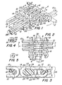
- Figure 1 illustrates a section of the coil members utilized in the seam construction according to the invention.
- the illustrated coil members are formed from a circular monofilament.
- Figure 2 illustrates a section of the seam construction with the coil members intermeshed and the pintle in place. This is illustrative of the final seam construction in the fabric on the papermaking machine. It also illustrates an alternative circular rather than shaped pintle.
- Figure 3 is a section through the line 3-3 of Figure 2 and illustrates the enlarged size of the pintle in the present seam construction.
- Figure 4 is a section through the line 4-4 of Figure 1 and illustrates the respective geometry of the winding legs versus the headcurves.
- Figure 5 is a section through the line 5-5 of Figure 1 and may be compared width Figure 4 as a further illustration of the configuration of the coil member in the present seam construction.
- Figure 6 illustrates a section of coil seam members fabricated from shaped monofilament yarn in accordance with the invention.
- Figure 7 shows the seam construction of Figure 6 with the coil members intermeshed and the pintle in place.
- Figure 7 also includes, in phantom, an alternative circular rather than shaped pintle.
- Figure 8 is a section through the line 8-8 of Figure 7 and illustrates the relationship of the enlarged coil member to the seam construction.
- Figure 9 is a section through the line 9-9 of Figure 6 .
- Figure 10 is a section through the line 10-10 of Figure 6 .
- FIG. 1 there is illustrated a portion of the seam construction prior to closing of the seam.
- the fabric has two opposed ends, 2 and 4, each of which is provided with a coil member 6 .
- the coil members 6 are produced from continuous monofilament yarns.
- the yarns in this configuration have a circular cross section.
- Each coil member 6 has a plurality of angular headcurves 16 which are adjacent the fabric body, not illustrated, and a plurality of vertical headcurves 14 which extend towards the opposite end of the fabric.
- the vertical end curves 14 of each spiral member 6 are spaced by a sufficient distance to permit intermeshing with the opposite spiral member. This configuration will be known to those skilled in the art.
- Each of the angular headcurves 16 is spaced apart by a distance which is sufficient to permit two machine direction yarns 10 to be received between adjacent headcurves. It will be understood by those skilled in the art that the angular headcurves are also angled in accordance with the space requirements between the adjacent vertical headcurves 14 . Thus, the space between angular headcurves will have a minimum determined by the space requirements of the two machine direction loops 10 and a maximum determined by the space requirements of the vertical headcurves.
- the angular headcurves and vertical headcurves are interconnected by upper or supporting winding legs 18 and lower or running winding legs 20 .
- winding legs 18 and 20 are generally parallel to each other and within the same vertical plane as the respective vertical headcurve 14 .
- both the upper and lower winding legs are provided with exterior flat surfaces 22 and interior flat surfaces 24 .
- the winding legs have both interior and exterior flat surfaces, however, the exterior flat surfaces 22 are not essential to obtain some of the benefits of the present invention. This distinction will be discussed in more detail hereinafter.
- the spiral members 6 will define an interior channel void 26 which has a greater distance between the interior flat surfaces 24 than would be available in a uniformly circular coil member without the flat surfaces 24 .
- the pintle channel which is defined by intermeshing the coil member 6 has a greater vertical dimension than would be available in a coil of the same uniformly sized monofilament without the flattened surfaces 24 .
- the coil members 6 have flattened support surfaces 22 . Spiral coils having flattened support surfaces usable with the present invention are disclosed in U.S. Patents 4,606,792 and 4,654,122.
- spiral coils may be formed by wrapping suitable synthetic monofilament materials about a mandrel.
- a mandrel is selected having a vertical dimension which corresponds to the required vertical dimension of the channel 26 .
- the coil material is then wrapped about the mandrel under sufficient conditions of heat and pressure to cause of a softening and flow of the coil material in the area of the interior surfaces 24 .
- the degree of heat and temperature required to cause formation of the surfaces 24 will depend upon the material selected for spiral member 6 .
- the interior and exterior radius of the vertical headcurve 14 is virtually unaltered by the modification of the surfaces 24 .
- the interior and exterior radii of the angular headcurves 16 are virtually unaltered.
- this attachment is accomplished in substantially the same manner as that utilized by the prior art to form a pin seam.
- the conventional pin seam one in four of the machine direction yarns is used to form the seaming loops.
- the present invention utilizes two in four of the machine direction yarns to bind the coil members 6 to the fabric body.
- the machine direction loops do not form the seaming loop, as in a common pin seam, rather they form the binding loops which secure the coil member to the fabric body.
- the seam construction is strengthened through the utilization of twice as many machine direction yarns.
- the machine direction yarns 10 which are utilized to forth the binding loops 10 for the coil members 6 are twinned or paired and are positioned between and over the angular headcurves 16 .
- the coil members 6 are intermeshed to forth a channel which receives the pintle 30 .
- the pintle 30 has a non-circular configuration and is generally oval in configuration.
- the pintle may be round, rectangular, bone shaped or of other configurations.
- the present invention is particularly suitable for use with a fabric seam tightening pintle of the type disclosed in copending U.S. application Serial No. 108,376, which is assigned to the same assignee as the present invention.
- the advantages of the flattened interior surfaces 24 can be seen by comparing seaming pintle 30 with the tying wire or pintle 12 which generally illustrates the maximum pintle height possible without modification of the interior air space or channel 26 . Absent the modification of the interior surface of the coil member 6, the vertical height of the seaming pintle 30 would be limited by the starting monofilament material in a manner similar to that illustrated for tying wire or pintle 12 .
- the numeral 28 in Figure 3 represents the caliper of the fabric. As this fabric caliper is reduced in an unmodified coil, the interior channel void 26 which accommodates the pintle 30 is likewise reduced. Accordingly, the vertical dimension of the pintle 30 is reduced and the strength of the seam is likewise reduced. With the present invention, reductions in the fabric caliper 28 do not necessitate further equivalent reductions in the pintle 30 .
- the flattened exterior surfaces 22 are maintained within the caliper of the seam. By so maintaining the flattened surfaces 22, it is possible to provide a seamed fabric which is essentially planar throughout its length without any differential in the seam area.
- the degree of flattening accomplished on the surface 22 will be rel at ed to the surface characteristics of the host fabric. As the fabric becomes courser or more open, the degree of flattening may be reduced so that the upper surface of the coil member 6 more nearly approaches the geometry of the headcurve portions.
- insertion of a circular pintle or an oval pintle with a reduced horizontal component will permit the seam to open to a greater degree and thereby alter the permeability and surface characteristics of the seam.
- the exterior flat surface 22 is in substantially the same plane as the upper most portion of the angular headcurve 16 and that the interior flat surface 24 is recessed from the lower plane defined by the bottom of the angular headcurve 16 .
- the coil member 6 in the area of the winding leg 18 will have a vertical dimension V less than the corresponding vertical dimension v of the angular headcurve 16 and a horizontal dimension H greater than the corresponding horizontal dimension h of the angular headcurve 16 .
- the lower winding leg 20 it is expected that certain applications will call for additional material on the lower winding leg, due to abrasion or wear characteristics of the papermaking equipment. Accordingly, it is contemplated that in certain embodiments the lower winding leg may not incorporate the exterior flat surface 22 . However, in all embodiments, it is contemplated that the interior flat surfaces 24 will be formed on winding legs 18 and 20 . At this time, it is believed that the use of interior flattened surfaces 24 on both winding legs is and 20 will assure alignment of the pintle during operation of the fabric.
- FIG. 6 through 10 there is illustrated an embodiment of the present invention which utilizes shaped or flat monofilament coil material.
- the coil members 56 may be prepared as previously described.
- the attachment of the coil members 56 to the body of the fabric will be as previously described.
- the use of a tying yarn or pintle 12 in connection with the loops 10 is preferred.
- Each of the coil members 56 will be comprised of a series of angular headcurves 66 and vertical headcurves 64 which are interconnected by winding legs 68 and 70 .
- the coil members 56 have exterior flattened surfaces 72 and interior flattened surfaces 74 are within the caliper 78 of the fabric.
- the increase in the horizontal dimension of the winding legs 68 and 70 relative to the headcurves will be less than that exhibited with round monofilament.
- the preshaped nature of the starting monofilament coil material means that there is less material available for reshaping or relocation. Notwithstanding this limitation, the advantage of increased pintle size may still be obtained with shaped monofilament.
- the vertical headcurve 64 will undergo a slight horizontal expansion which results in the headcurve 64 having a slightly larger horizontal component than the angular headcurve 66 .
- the horizontal component of the vertical headcurve 64 has been found to be slightly less than that of the winding legs 68 and 70 .
- the phantom lines 82 indicate a vertical headcurve which has maintained the same horizontal dimension as the angular headcurve 66 .
- a circular pintle 40 and 90 respectively.
- a circular pintle may be utilized as a means of accomplishing this end. Utilization of a circular pintle will result in a more open seam configuration, but will still benefit from the increased pintle size.
- each of the coil members 6 may have a uniform geometric throughout the headcurve and winding legs.
- This alternative embodiment will find use in those higher caliper fabrics where further modification of the winding legs is not necessary to achieve caliper height but it is desirable to include an enlarged pintle in the seam construction.
- each of the coil members 6 would be comprised of a single monofilament having a flattened or generally rectangular configuration.
- the entire monofilament would have a cross sectional geometry which corresponds to that illustrated in Figure 10 for the headcurve 66 .
- the shaped monofilament is utilized instead of the circular monofilament.
- the resulting coil member will define a pintle receiving channel having a larger cross sectional area than could be accomplished with a coil member having a circular yarn of equal denier within the same maximum caliper.
- the pintles may utilize configurations of the type disclosed as stuffers in U.S. Patent 4,567,077 as a means for further controlling characteristics such as air and moisture permeability.
- the coil member 6 in certain embodiments, may have flocking or fiber segments adhered thereto, such as disclosed in U.S. Patent 4,654,122.
- the present invention provides a seam construction with increased strength in the seam area in general and in the pintle area in particular. Furthermore, it will be recognized that the present seam incorporates the advantages of both prior art pin and coil seams.
Landscapes
- Engineering & Computer Science (AREA)
- General Engineering & Computer Science (AREA)
- Mechanical Engineering (AREA)
- Paper (AREA)
- Storage Of Web-Like Or Filamentary Materials (AREA)
- Details Of Garments (AREA)
Priority Applications (1)
| Application Number | Priority Date | Filing Date | Title |
|---|---|---|---|
| AT89304732T ATE99365T1 (de) | 1988-10-14 | 1989-05-10 | Saumbildung fuer ein papiermachergewebe. |
Applications Claiming Priority (2)
| Application Number | Priority Date | Filing Date | Title |
|---|---|---|---|
| US07/257,963 US4862926A (en) | 1988-10-14 | 1988-10-14 | Shaped monofilament coil seam and fabrics |
| US257963 | 1994-06-07 |
Publications (2)
| Publication Number | Publication Date |
|---|---|
| EP0364066A1 true EP0364066A1 (fr) | 1990-04-18 |
| EP0364066B1 EP0364066B1 (fr) | 1993-12-29 |
Family
ID=22978526
Family Applications (1)
| Application Number | Title | Priority Date | Filing Date |
|---|---|---|---|
| EP89304732A Expired - Lifetime EP0364066B1 (fr) | 1988-10-14 | 1989-05-10 | Jonction des extrémités du tissu d'une machine à papier |
Country Status (7)
| Country | Link |
|---|---|
| US (1) | US4862926A (fr) |
| EP (1) | EP0364066B1 (fr) |
| AT (1) | ATE99365T1 (fr) |
| AU (1) | AU606522B2 (fr) |
| CA (1) | CA1320066C (fr) |
| DE (1) | DE68911839T2 (fr) |
| NZ (1) | NZ229117A (fr) |
Cited By (5)
| Publication number | Priority date | Publication date | Assignee | Title |
|---|---|---|---|---|
| EP0837179A3 (fr) * | 1996-10-11 | 1998-08-05 | Albany International Corp. | Toile pour papeterie contenant des paires de fils sens machine identiques, tissés ensemble |
| EP0851057A3 (fr) * | 1996-12-02 | 1998-08-19 | Albany International Corp. | Toíle de papeterie avec des paires de fils de chaíne différents tissés ensemble |
| US6241081B1 (en) | 1997-02-18 | 2001-06-05 | Voith Fabrics Heidenheim Gmbh & Co. Kg | Modified spiral seam arrangement |
| WO2003054416A1 (fr) * | 2001-12-10 | 2003-07-03 | Lippert Pintlepin Mfg. Inc. | Spirale permettant de raccorder les extremites des segments d'une courroie sans fin |
| US9471969B2 (en) | 2014-06-23 | 2016-10-18 | Exxonmobil Upstream Research Company | Methods for differential image quality enhancement for a multiple detector system, systems and use thereof |
Families Citing this family (11)
| Publication number | Priority date | Publication date | Assignee | Title |
|---|---|---|---|---|
| US4976293A (en) * | 1990-01-31 | 1990-12-11 | Niagara Lockport Industries Inc. | Built up seam for papermakers fabric |
| US5480604A (en) * | 1991-01-23 | 1996-01-02 | Asten, Inc. | Molded seam for papermakers fabric and method |
| US5269129A (en) * | 1992-02-14 | 1993-12-14 | Aluminum Company Of America | Chain of fiber-reinforced resin composite material |
| US5488976A (en) * | 1994-03-16 | 1996-02-06 | Asten, Inc. | Coil seam for single layer industrial fabrics having an uneven shed pattern |
| US5601120A (en) * | 1996-01-30 | 1997-02-11 | Asten, Inc. | Pin seam with double end loops and method |
| US5875822A (en) * | 1996-06-25 | 1999-03-02 | Albany International Corp. | Polyamide spiral seam for seamed papermakers' fabrics |
| US6643899B2 (en) | 2000-06-16 | 2003-11-11 | André Corriveau | Spiral for interconnecting ends of endless belt segments |
| US6880583B2 (en) * | 2002-05-29 | 2005-04-19 | Albany International Corp. | Papermaker's and industrial fabric seam |
| US8640862B2 (en) * | 2006-04-10 | 2014-02-04 | Albany International Corp. | Seam-on laminated belt |
| US10689796B2 (en) | 2013-03-14 | 2020-06-23 | Albany International Corp. | Infinity shape coil for spiral seams |
| US10689807B2 (en) | 2013-03-14 | 2020-06-23 | Albany International Corp. | Industrial fabrics comprising infinity shape coils |
Citations (5)
| Publication number | Priority date | Publication date | Assignee | Title |
|---|---|---|---|---|
| DE2429162A1 (de) * | 1974-06-18 | 1976-01-08 | Heinz Kerber | Endlose verbindung von mehrlagigen trockenfilzen- und sieben |
| US4315049A (en) * | 1979-12-06 | 1982-02-09 | Asten Group, Incorporated | Stitchless low bulk, pin-type seam for use in paper making equipment fabrics, such as dryer felts |
| GB2134062A (en) * | 1983-01-26 | 1984-08-08 | Scapa Porritt Ltd | Link belts |
| EP0161579A2 (fr) * | 1984-05-01 | 1985-11-21 | JWI Ltd. | Toile de séchage comprenant des fils de chaîne en polyphénylène sulphide extrudable au fondu |
| US4695015A (en) * | 1985-03-22 | 1987-09-22 | Tamfelt Oy Ab | Improvements relating to belts of inter-woven spiral wires |
Family Cites Families (9)
| Publication number | Priority date | Publication date | Assignee | Title |
|---|---|---|---|---|
| GB1266891A (fr) * | 1969-02-21 | 1972-03-15 | ||
| SE355389B (fr) * | 1970-12-31 | 1973-04-16 | Nordiska Maskinfilt Ab | |
| US4314589A (en) * | 1978-10-23 | 1982-02-09 | Jwi Ltd. | Duplex forming fabric |
| US4438788A (en) * | 1980-09-30 | 1984-03-27 | Scapa Inc. | Papermakers belt formed from warp yarns of non-circular cross section |
| FR2494318B1 (fr) * | 1980-11-14 | 1986-10-10 | Feutres Papeteries Tissus Indl | Bande constituee de spirales |
| US4574435A (en) * | 1985-03-12 | 1986-03-11 | Albany International Corp. | Seam construction for papermachine clothing |
| FR2578869B1 (fr) * | 1985-03-12 | 1988-09-30 | Binet Feutres Sa | Dispositif de jonction pour feutre de presse humide et toile de papeterie. |
| DE3581930D1 (de) * | 1985-03-26 | 1991-04-04 | Asten Group | Endloses siebband fuer papiermaschinen o.dgl. |
| DE3633395A1 (de) * | 1986-10-01 | 1988-04-14 | Heimbach Gmbh Thomas Josef | Maschinenbespannung, insbesondere papiermaschinenfilz oder -sieb |
-
1988
- 1988-10-14 US US07/257,963 patent/US4862926A/en not_active Expired - Fee Related
-
1989
- 1989-05-10 EP EP89304732A patent/EP0364066B1/fr not_active Expired - Lifetime
- 1989-05-10 DE DE68911839T patent/DE68911839T2/de not_active Expired - Fee Related
- 1989-05-10 AT AT89304732T patent/ATE99365T1/de not_active IP Right Cessation
- 1989-05-15 NZ NZ229117A patent/NZ229117A/xx unknown
- 1989-05-15 CA CA000599640A patent/CA1320066C/fr not_active Expired - Fee Related
- 1989-05-18 AU AU34938/89A patent/AU606522B2/en not_active Ceased
Patent Citations (5)
| Publication number | Priority date | Publication date | Assignee | Title |
|---|---|---|---|---|
| DE2429162A1 (de) * | 1974-06-18 | 1976-01-08 | Heinz Kerber | Endlose verbindung von mehrlagigen trockenfilzen- und sieben |
| US4315049A (en) * | 1979-12-06 | 1982-02-09 | Asten Group, Incorporated | Stitchless low bulk, pin-type seam for use in paper making equipment fabrics, such as dryer felts |
| GB2134062A (en) * | 1983-01-26 | 1984-08-08 | Scapa Porritt Ltd | Link belts |
| EP0161579A2 (fr) * | 1984-05-01 | 1985-11-21 | JWI Ltd. | Toile de séchage comprenant des fils de chaîne en polyphénylène sulphide extrudable au fondu |
| US4695015A (en) * | 1985-03-22 | 1987-09-22 | Tamfelt Oy Ab | Improvements relating to belts of inter-woven spiral wires |
Cited By (5)
| Publication number | Priority date | Publication date | Assignee | Title |
|---|---|---|---|---|
| EP0837179A3 (fr) * | 1996-10-11 | 1998-08-05 | Albany International Corp. | Toile pour papeterie contenant des paires de fils sens machine identiques, tissés ensemble |
| EP0851057A3 (fr) * | 1996-12-02 | 1998-08-19 | Albany International Corp. | Toíle de papeterie avec des paires de fils de chaíne différents tissés ensemble |
| US6241081B1 (en) | 1997-02-18 | 2001-06-05 | Voith Fabrics Heidenheim Gmbh & Co. Kg | Modified spiral seam arrangement |
| WO2003054416A1 (fr) * | 2001-12-10 | 2003-07-03 | Lippert Pintlepin Mfg. Inc. | Spirale permettant de raccorder les extremites des segments d'une courroie sans fin |
| US9471969B2 (en) | 2014-06-23 | 2016-10-18 | Exxonmobil Upstream Research Company | Methods for differential image quality enhancement for a multiple detector system, systems and use thereof |
Also Published As
| Publication number | Publication date |
|---|---|
| ATE99365T1 (de) | 1994-01-15 |
| AU3493889A (en) | 1990-04-26 |
| DE68911839T2 (de) | 1994-05-19 |
| DE68911839D1 (de) | 1994-02-10 |
| CA1320066C (fr) | 1993-07-13 |
| EP0364066B1 (fr) | 1993-12-29 |
| AU606522B2 (en) | 1991-02-07 |
| US4862926A (en) | 1989-09-05 |
| NZ229117A (en) | 1991-01-29 |
Similar Documents
| Publication | Publication Date | Title |
|---|---|---|
| EP0364066B1 (fr) | Jonction des extrémités du tissu d'une machine à papier | |
| CA1257798A (fr) | Couture spirale pour tissus monofilament multicouche a fils de chaine plats | |
| US4896702A (en) | Seam construction for papermaking fabrics | |
| US4883096A (en) | Seam design for seamed felts | |
| US4846231A (en) | Seam design for seamed felts | |
| US5015220A (en) | Seam for work fabric and method of manufacture thereof | |
| EP0425523A1 (fr) | Materiaux de fabrication de papier. | |
| WO1991014884A1 (fr) | Couture pour tissus de travail et procede de realisation de celle-ci | |
| US5787936A (en) | Laminated papermaker's fabric having projecting seaming loops | |
| EP0817883B1 (fr) | Habillage comportant une couture et spirale utilisable dans ce type de couture | |
| US5601120A (en) | Pin seam with double end loops and method | |
| US5488976A (en) | Coil seam for single layer industrial fabrics having an uneven shed pattern | |
| US5005610A (en) | Papermaking fabric pin seam with braided yarns in joining loops | |
| US5411062A (en) | Papermakers fabric with orthogonal machine direction yarn seaming loops | |
| US7141144B2 (en) | Multi-layer woven seam baseweave having different sized seam attachments | |
| EP1540203B1 (fr) | Tissu industriel a couture sur machine, a anneaux de renforcement de coutures | |
| CA1329502C (fr) | Fil d'agrafage pour points de toile de machine a papier | |
| EP1597428B1 (fr) | Tissu industriel pouvant etre assemble en machine et etant constitue d'anneaux interconnectes | |
| USRE35966E (en) | Papermakers fabric with orthogonal machine direction yarn seaming loops | |
| NZ235990A (en) | Pin seam for paper machine endless fabric belt: pintle held within flattened section spirals | |
| GB2325881A (en) | Seam construction for papermaking fabric |
Legal Events
| Date | Code | Title | Description |
|---|---|---|---|
| PUAI | Public reference made under article 153(3) epc to a published international application that has entered the european phase |
Free format text: ORIGINAL CODE: 0009012 |
|
| AK | Designated contracting states |
Kind code of ref document: A1 Designated state(s): AT BE CH DE ES FR GB GR IT LI LU NL SE |
|
| 17P | Request for examination filed |
Effective date: 19900924 |
|
| 17Q | First examination report despatched |
Effective date: 19920408 |
|
| GRAA | (expected) grant |
Free format text: ORIGINAL CODE: 0009210 |
|
| AK | Designated contracting states |
Kind code of ref document: B1 Designated state(s): AT BE CH DE ES FR GB GR IT LI LU NL SE |
|
| PG25 | Lapsed in a contracting state [announced via postgrant information from national office to epo] |
Ref country code: AT Effective date: 19931229 Ref country code: IT Free format text: LAPSE BECAUSE OF FAILURE TO SUBMIT A TRANSLATION OF THE DESCRIPTION OR TO PAY THE FEE WITHIN THE PRE;WARNING: LAPSES OF ITALIAN PATENTS WITH EFFECTIVE DATE BEFORE 2007 MAY HAVE OCCURRED AT ANY TIME BEFORE 2007. THE CORRECT EFFECTIVE DATE MAY BE DIFFERENT FROM THE ONE RECORDED.SCRIBED TIME-LIMIT Effective date: 19931229 Ref country code: GR Free format text: LAPSE BECAUSE OF FAILURE TO SUBMIT A TRANSLATION OF THE DESCRIPTION OR TO PAY THE FEE WITHIN THE PRESCRIBED TIME-LIMIT Effective date: 19931229 Ref country code: BE Effective date: 19931229 Ref country code: SE Effective date: 19931229 Ref country code: LI Effective date: 19931229 Ref country code: CH Effective date: 19931229 Ref country code: ES Free format text: THE PATENT HAS BEEN ANNULLED BY A DECISION OF A NATIONAL AUTHORITY Effective date: 19931229 Ref country code: NL Effective date: 19931229 |
|
| REF | Corresponds to: |
Ref document number: 99365 Country of ref document: AT Date of ref document: 19940115 Kind code of ref document: T |
|
| REF | Corresponds to: |
Ref document number: 68911839 Country of ref document: DE Date of ref document: 19940210 |
|
| ET | Fr: translation filed | ||
| REG | Reference to a national code |
Ref country code: CH Ref legal event code: PL |
|
| PG25 | Lapsed in a contracting state [announced via postgrant information from national office to epo] |
Ref country code: GB Effective date: 19940510 |
|
| PG25 | Lapsed in a contracting state [announced via postgrant information from national office to epo] |
Ref country code: LU Free format text: LAPSE BECAUSE OF NON-PAYMENT OF DUE FEES Effective date: 19940531 |
|
| NLV1 | Nl: lapsed or annulled due to failure to fulfill the requirements of art. 29p and 29m of the patents act | ||
| PLBE | No opposition filed within time limit |
Free format text: ORIGINAL CODE: 0009261 |
|
| STAA | Information on the status of an ep patent application or granted ep patent |
Free format text: STATUS: NO OPPOSITION FILED WITHIN TIME LIMIT |
|
| 26N | No opposition filed | ||
| GBPC | Gb: european patent ceased through non-payment of renewal fee |
Effective date: 19940510 |
|
| PGFP | Annual fee paid to national office [announced via postgrant information from national office to epo] |
Ref country code: DE Payment date: 20000508 Year of fee payment: 12 |
|
| PGFP | Annual fee paid to national office [announced via postgrant information from national office to epo] |
Ref country code: FR Payment date: 20000510 Year of fee payment: 12 |
|
| PG25 | Lapsed in a contracting state [announced via postgrant information from national office to epo] |
Ref country code: FR Free format text: LAPSE BECAUSE OF NON-PAYMENT OF DUE FEES Effective date: 20020131 |
|
| PG25 | Lapsed in a contracting state [announced via postgrant information from national office to epo] |
Ref country code: DE Free format text: LAPSE BECAUSE OF NON-PAYMENT OF DUE FEES Effective date: 20020301 |