EP0364076B1 - Kraftstoffeinspritzpumpe - Google Patents
Kraftstoffeinspritzpumpe Download PDFInfo
- Publication number
- EP0364076B1 EP0364076B1 EP89307760A EP89307760A EP0364076B1 EP 0364076 B1 EP0364076 B1 EP 0364076B1 EP 89307760 A EP89307760 A EP 89307760A EP 89307760 A EP89307760 A EP 89307760A EP 0364076 B1 EP0364076 B1 EP 0364076B1
- Authority
- EP
- European Patent Office
- Prior art keywords
- plunger
- piston
- fuel
- bore
- movement
- Prior art date
- Legal status (The legal status is an assumption and is not a legal conclusion. Google has not performed a legal analysis and makes no representation as to the accuracy of the status listed.)
- Expired - Lifetime
Links
- 239000000446 fuel Substances 0.000 title claims description 75
- 238000005086 pumping Methods 0.000 title claims description 18
- 239000012530 fluid Substances 0.000 claims description 20
- 238000002347 injection Methods 0.000 claims description 6
- 239000007924 injection Substances 0.000 claims description 6
- 238000002485 combustion reaction Methods 0.000 claims description 3
- 238000007789 sealing Methods 0.000 claims description 2
- 230000000694 effects Effects 0.000 description 3
- 230000006835 compression Effects 0.000 description 2
- 238000007906 compression Methods 0.000 description 2
- 230000002093 peripheral effect Effects 0.000 description 2
- 239000000463 material Substances 0.000 description 1
- 238000011144 upstream manufacturing Methods 0.000 description 1
Images
Classifications
-
- F—MECHANICAL ENGINEERING; LIGHTING; HEATING; WEAPONS; BLASTING
- F02—COMBUSTION ENGINES; HOT-GAS OR COMBUSTION-PRODUCT ENGINE PLANTS
- F02M—SUPPLYING COMBUSTION ENGINES IN GENERAL WITH COMBUSTIBLE MIXTURES OR CONSTITUENTS THEREOF
- F02M41/00—Fuel-injection apparatus with two or more injectors fed from a common pressure-source sequentially by means of a distributor
- F02M41/08—Fuel-injection apparatus with two or more injectors fed from a common pressure-source sequentially by means of a distributor the distributor and pumping elements being combined
- F02M41/14—Fuel-injection apparatus with two or more injectors fed from a common pressure-source sequentially by means of a distributor the distributor and pumping elements being combined rotary distributor supporting pump pistons
- F02M41/1405—Fuel-injection apparatus with two or more injectors fed from a common pressure-source sequentially by means of a distributor the distributor and pumping elements being combined rotary distributor supporting pump pistons pistons being disposed radially with respect to rotation axis
- F02M41/1411—Fuel-injection apparatus with two or more injectors fed from a common pressure-source sequentially by means of a distributor the distributor and pumping elements being combined rotary distributor supporting pump pistons pistons being disposed radially with respect to rotation axis characterised by means for varying fuel delivery or injection timing
-
- F—MECHANICAL ENGINEERING; LIGHTING; HEATING; WEAPONS; BLASTING
- F02—COMBUSTION ENGINES; HOT-GAS OR COMBUSTION-PRODUCT ENGINE PLANTS
- F02M—SUPPLYING COMBUSTION ENGINES IN GENERAL WITH COMBUSTIBLE MIXTURES OR CONSTITUENTS THEREOF
- F02M59/00—Pumps specially adapted for fuel-injection and not provided for in groups F02M39/00 -F02M57/00, e.g. rotary cylinder-block type of pumps
- F02M59/20—Varying fuel delivery in quantity or timing
- F02M59/36—Varying fuel delivery in quantity or timing by variably-timed valves controlling fuel passages to pumping elements or overflow passages
- F02M59/365—Varying fuel delivery in quantity or timing by variably-timed valves controlling fuel passages to pumping elements or overflow passages valves being actuated by the fluid pressure produced in an auxiliary pump, e.g. pumps with differential pistons; Regulated pressure of supply pump actuating a metering valve, e.g. a sleeve surrounding the pump piston
Definitions
- This invention relates to a fuel pumping apparatus for supplying fuel to an internal combustion engine, the apparatus being of the kind including a plunger slidably mounted in a bore, a cam for imparting inward movement to the plunger, an outlet through which fuel can flow during inward movement of the plunger the outlet in use, being connected to a fuel injection nozzle of the associated engine and means for feeding fuel to the bore to effect outward movement of the plunger.
- An alternative approach is to arrange for the bore to be completely filled with fuel and to spill a portion of the fuel expelled from the bore during the inward movement of the plunger.
- the spillage of fuel may be effected using a so called spill muff which surrounds the plunger or a rotary member mounting the plunger and which with the plunger or rotary member defines a spill path which is opened at a predetermined position during the inward movement of the plunger.
- the aforesaid position can be varied to enable the amount of fuel supplied to the engine to be controlled.
- CH-A-350833 describes a fuel pumping apparatus having a reciprocable pumping plunger mounted in a bore and actuated by a cam so that during inward movement of the plunger fuel is delivered through an outlet providing a spill valve is closed.
- the spill valve is in the form of a slide valve biased towards one end of a cylinder by a spring the force exerted by which can be adjusted.
- the one end of the cylinder is supplied with fluid by means of a further plunger which is operated in synchronism with the pumping plunger and fluid can escape from the one end of the cylinder through a variable restrictor the size of which depends upon the position of the slide valve.
- the slide valve moves to the open position to spill fuel, only when the fluid pressure upstream of the restrictor rises to a value such that the spring force is overcome. A speed governing effect is therefore obtained.
- a non return valve is provided between the one end of the cylinder and the bore containing the further plunger and in order to allow the slide valve to return to the one end of the cylinder at the end of the pumping stroke of the pumping plunger a further valve which also comprises a spring loaded slide valve is provided. This valve is biased by its spring to the open position and is closed by the initial volume of fluid delivered by the further plunger. On the return stroke of the further plunger the further valve connects the one end of the cylinder to drain.
- EP-A-0069115 shows a spring biased piston which is contained in a cylinder communicating with the pumping chamber of a reciprocable plunger fuel injection pump the plunger of which can be moved angularly to control the quantity of fuel delivered.
- the piston is moved outwardly into engagement with an adjustable stop during the initial portion of the pumping stroke of the plunger before fuel is delivered to an associated engine. Adjustment of the stop alters the timing of fuel delivery to the engine.
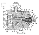
- the apparatus comprises a multi part body 10 in which is housed a rotary cylindrical distributor member 11, the distributor member being coupled to a drive shaft (not shown) which is connected to and therefore rotates in synchronism with the associated engine.
- the distributor member has an enlarged portion 12 in which is formed a pair of diametrically disposed bores 13, 14.
- the bore 13 mounts a pair of pumping plungers 15 which at their outer ends engage cam followers 16 each of the cam followers having a roller 17 which engages the internal peripheral service of an annular cam ring 18 mounted within the body part.
- the cam ring has on its internal peripheral surface four equi-angularly spaced cam lobes.
- the space defined between the plungers 15 communicates with a longitudinally extending passage 19 formed in the distributor member and which communicates with in the particular example, four equi-angularly spaced and radially extending inlet passages 20.
- the passages 20 can register in turn and as the distributor member rotates, with an inlet port 21 formed in the body part and in constant communication with a low pressure fuel supply pump 22.
- the passage 19 also communicates with a delivery passage 23 which extends to the periphery of the distributor member and is positioned to communicate in turn as the distributor member rotates, with four equi-angularly spaced outlets 24 which in use communicate with the injection nozzles respectively of the associated engine.
- a spill valve which is generally indicated at 25.
- the spill valve comprises a body member 26 which is in the example, in screw thread engagement with the distributor member.
- the body member defines a head 27 on the underside of which is formed a frusto conical seating 28 and adjacent the head the body member is provided with a circumferential groove which by means of an axially extending passage in the body member, is in constant communication with the passage 19 in the distributor member.
- Slidable about the spill valve body member is a spill valve member 29 which is of hollow cylindrical form having an outwardly extending flange and shaped for engagement with the seating.
- the flange is engaged by one end of a coiled compression spring 39 the other end of which bears against an annular abutment 40 which is located against a step formed on the periphery of the distributor member the abutment 40 extends outwardly beyond the distributor member and also engages a step defined in a recess 41 defined in the body.
- the open end of the recess is closed by a closure member 42 in which is formed a cylinder 43.
- a closure member 42 in which is formed a cylinder 43.
- a first piston 44 which when fluid under pressure is supplied to the cylinder, is urged towards the head 27 of the spill valve.
- a stirrup is interposed between the piston 44 and the spill valve member 29, the stirrup being slidable about the circumferential surface of the head 27.
- a further cylinder 45 is defined in the body part the cylinder 45 containing a second piston 46 which has an extension 47.
- the piston 46 is biased towards the closed end of the cylinder by means of a coiled compression spring 48 and the two cylinders 45 and 43 are in communication with each other by way of a passage 49 formed in the body part and the end closure member 42.
- the passage 49 communicates with a circumferential groove 50 formed on the periphery of the distributor member and the groove 50 is in constant communication with the intermediate portion of the bore 14.
- Located in the bore 14 are a further pair of plungers 51 which at their outer ends engage the followers 16 respectively.
- Communicating with the circumferential groove 50 are four equi-angularly spaced longitundinal grooves 52 which are positioned to register with a supply port 53 formed in the body part and communicating with the low pressure supply pump 22.
- the grooves 52 are positioned to register with the supply port 53 at the same time that the inlet passages 20 register with the inlet port 21.
- the extension 47 of the piston 46 is engageable with a stop means which in the example is shown as a wedge member 54 and the wedge member can be moved to vary the extent of allowed outward movement of the piston 46, by a governor system 55.
- a stop means which in the example is shown as a wedge member 54 and the wedge member can be moved to vary the extent of allowed outward movement of the piston 46, by a governor system 55.
- the plungers 51 are moved inwardly, the fuel displaced from the bore 14 is supplied to the cylinders 43 and 45.
- the strength of the spring 39 and the area of the piston 44 are such in relation to the strength of the spring 48 and the area of the piston 46, that the piston 46 moves outwardly in preference to movement of the piston 44.
- the initial volume of fluid in this case fuel, displaced by the plungers 51 is absorbed by outward movement of the piston 46 and only when the extension 47 engages the wedge member 54 does the pressure in the cylinders rise to the extent that movement of the piston 44 occurs to displace the spill valve member against the action of its spring.
- the plungers 15 and 51 are moved inwardly at the same time and hence so long as the piston 46 is moving outwardly, fuel will be delivered to the associated engine.
- the spill valve member is lifted from the seating 28 and the further quantity of fuel delivered by the plungers 15 is spilled into the recess 41.
- a port 56 which is formed in the wall of the bore 14 and which can register with a circumferential groove 57 formed on one of the plungers 51 when the plunger has moved outwardly its maximum extent.
- the groove 57 communicates with the portion of the bore 14 lying between the plungers. When the groove uncovers the port 56 a flow of fuel can take place from the bore 14, the fuel being supplied from the low pressure pump.
- a restricted vent passage which is shown in dotted outline at 58 the passage 58 is positioned to communicate with one of the grooves 52 when another one of the grooves is in communication with the supply port 53.
- the volume of fuel which is displaced by the plungers 51 be capable of being absorbed by movement of the pistons 44 and 46 other wise an hydraulic lock will be created.
- the wedge member When the wedge member is set to provide the maximum amount of fuel the piston 46 undergoes its maximum movement and the movement of the piston 44 will only be sufficient to ensure that the spill valve member is lifted from its seating so that the pressure of fuel developed by the plungers 15 is relieved before the followers move over the crests of the cam lobes.
- the wedge member is set to provide the minimum flow of fuel to the associated engine, the movement of the piston 46 is substantially less and hence the piston 44 must be capable of moving a sufficient extent to absorb the majority of the fuel displaced by the plungers 51. Movement of the piston 44 requires corresponding movement of the valve member 29 and if it is not possible to provide the required range of movement of the valve member, the bore 43 may be provided with a spill port which is uncovered after a predetermined movement of the piston 44.
- the apparatus as described provides a constant start of fuel delivery irrespective of the quantity of fuel supplied to the associated engine and furthermore the fuel pressure intermediate the pumping plungers 15 is relieved before the cam followers move over the crests of the cam lobes. Since advance of the timing of delivery of fuel by the apparatus will be required with increasing engine speed, the cam ring 18 can be moved angularly in the usual manner.
- the governor system 55 can be of a mechanical nature or it may be an electronic system with an actuator to position the wedge member and a position sensor to provide a feedback signal to the system.
Landscapes
- Engineering & Computer Science (AREA)
- Chemical & Material Sciences (AREA)
- Combustion & Propulsion (AREA)
- Mechanical Engineering (AREA)
- General Engineering & Computer Science (AREA)
- Physics & Mathematics (AREA)
- Fluid Mechanics (AREA)
- Fuel-Injection Apparatus (AREA)
- Reciprocating Pumps (AREA)
- Details Of Reciprocating Pumps (AREA)
Claims (8)
- Kraftstoffpumpvorrichtung zur Zuführung von Kraftstoff zu einer Brennkraftmaschine mit einem Pumpenplungerkolben (15), der in einer Bohrung (13) montiert ist, einem Nocken (18), um den Plungerkolben (15) einwärts zu bewegen, einem Auslaß (24), durch den der Kraftstoff während der Einwärtsbewegung des Plungerkolbens (15) fließen kann, wobei der Auslaß (24) im Betrieb an eine Kraftstoffeinspritzdüse angeschlossen ist, Einrichtungen (22) zur Zuführung von Kraftstoff in die Bohrung (13), einem Abführventil (25), mit dem Kraftstoff während der Einwärtsbewegung des Plungerkolbens (15) aus der Bohrung (13) abgeführt werden kann, um die durch den Auslaß (24) abgegebene Kraftstoffmenge festzulegen, einem weiteren Plungerkolben (51), der snychron zum Pumpenplungerkolben (15) betätigbar ist und in einer weiteren Bohrung (14) montiert ist, aus der Strömungsmittel während der Einwärtsbewegung des weiteren Plungerkolbens verdrängt wird, wobei das Abführventil (25) ein Abführventilelement (29) aufweist, das in die geschlossene Position vorgespannt ist, einen ersten Kolben (44), der in einem ersten Zylinder (43) gleiten kann, welcher mit der weiteren Bohrung (14) in Verbindung steht, um Strömungsmittel aufzunehmen, das während der Einwärtsbewegung des weiteren Plungerkolbens verdrängt wird, wobei der erste Kolben (44) mit dem Abführventilelement (29) verbunden ist, so daß dann, wenn der Druck im ersten Zylinder (43) einen vorgegebenen Wert erreicht, das Abführventilelement (29) in eine offene Position bewegt wird, einen zweiten Kolben (46), der gleitend in einem zweiten Zylinder (45) gelagert ist, welcher mit der weiteren Bohrung (14) in Verbindung steht, um während der Einwärtsbewegung des weiteren Plungerkolbens verdrängtes Strömungsmittel aufzunehmen, Federeinrichtungen (48), die den zweiten Kolben (46) gegen die Wirkung des Strömungsmitteldrucks in der weiteren Bohrung (14) vorspannen, wobei der zur Bewegung des zweiten Kolbens (46) gegen die Wirkung der Federeinrichtungen (48) erforderliche Druck geringer ist als der vorgegebene Druckwert, der zur Bewegung des ersten Kolbens (44) erforderlich ist, und Anschlageinrichtungen (54) zur Begrenzung der Bewegung des zweiten Kolbens (46), dadurch gekennzeichnet, daß die Anschlageinrichtungen (54) verstellbar sind und daß eine Steuereinrichtung (55) zur Veränderung der Einstellung der Anschlageinrichtungen (54) vorgesehen ist, wobei das gesamte Strömungsmittel, das aus der weiteren Bohrung (14) verdrängt ist, zu einer Bewegung des zweiten Kolbens (46) und mindestens zur Anfangsbewegung des ersten Kolbens (44) führt und wobei das während der Einwärtsbewegung des Plungerkolbens und des weiteren Plungerkolbens (15, 51) verdrängte Strömungsmittel anfangs durch die Bewegung des zweiten Kolbens (46) absorbiert wird, bis dessen Bewegung durch die Anschlageinrichtungen (54) gestoppt wird, so daß der Strömungsmitteldruck im ersten Zylinder (43) mindestens auf den vorgegebenen Wert ansteigt und das Abführventilelement (29) in die offene Position bewegt wird, um die Abgabe von Kraftstoff durch den Auslaß (24) zu beenden.
- Vorrichtung nach Anspruch 1, gekennzeichnet durch Einrichtungen (52, 53), durch die Strömungsmittel unter Druck der weiteren Bohrung (14) und den Zylindern (43, 45) während der Auswärtsbewegung des weiteren Plungerkolbens (51) zugeführt werden kann.
- Vorrichtung nach Anspruch 1 oder 2, dadurch gekennzeichnet, daß das Abführventilelement (29) die Form einer Hülse besitzt, die um einen Ventilkörper (26) gleitbar ist, wobei der Ventilkörper einen Kopf (27) aufweist, der Kopf und die Hülse zusammenwirkende Sitzflächen bilden und der Ventilkörper eine Nut benachbart zum Kopf aufweist, die mit der zuerst erwähnten Bohrung (13) in Verbindung steht.
- Vorrichtung nach Anspruch 3, gekennzeichnet durch einen Bügel, der um den Kopf (27) gleitbar ist und mit dem ersten Kolben (44) und der Hülse in Eingriff steht, wobei die Hülse einen Flansch aufweist, mit dem eine Feder (39) in Eingriff steht, die die Sitzflächen in dichtenden Eingriff preßt.
- Vorrichtung nach Anspruch 4 mit einer drehbaren Verteilereinrichtung (11), in der die Bohrung und die weitere Bohrung (13, 14) ausgebildet sind, dadurch gekennzeichnet, daß der Ventilkörper (26) axial am Verteilerelement (11) montiert ist.
- Vorrichtung nach Anspruch 5, dadurch gekennzeichnet, daß der erste Zylinder (43) koaxial zum Verteilerelement (11) angeordnet ist.
- Vorrichtung nach Anspruch 1, dadurch gekennzeichnet, daß der weitere Plungerkolben (51) in seiner äußersten Position in der weiteren Bohrung (14) einen Entlüftungsweg (57, 56) aus der weiteren Bohrung öffnet.
- Vorrichtung nach Anspruch 1, gekennzeichnet durch einen Abflußkanal, der vom ersten Kolben (44) nach einer vorgegebenen Bewegung des Kolbens gegen die Wirkung der Feder (39) freigegeben wird.
Applications Claiming Priority (2)
| Application Number | Priority Date | Filing Date | Title |
|---|---|---|---|
| GB8823846 | 1988-10-11 | ||
| GB888823846A GB8823846D0 (en) | 1988-10-11 | 1988-10-11 | Fuel pumping apparatus |
Publications (3)
| Publication Number | Publication Date |
|---|---|
| EP0364076A2 EP0364076A2 (de) | 1990-04-18 |
| EP0364076A3 EP0364076A3 (en) | 1990-09-19 |
| EP0364076B1 true EP0364076B1 (de) | 1993-07-21 |
Family
ID=10645039
Family Applications (1)
| Application Number | Title | Priority Date | Filing Date |
|---|---|---|---|
| EP89307760A Expired - Lifetime EP0364076B1 (de) | 1988-10-11 | 1989-07-31 | Kraftstoffeinspritzpumpe |
Country Status (6)
| Country | Link |
|---|---|
| US (1) | US4896645A (de) |
| EP (1) | EP0364076B1 (de) |
| JP (1) | JPH02169857A (de) |
| DE (1) | DE68907683T2 (de) |
| ES (1) | ES2043023T3 (de) |
| GB (1) | GB8823846D0 (de) |
Families Citing this family (12)
| Publication number | Priority date | Publication date | Assignee | Title |
|---|---|---|---|---|
| DE3844363A1 (de) * | 1988-12-30 | 1990-07-05 | Bosch Gmbh Robert | Elektrisch gesteuerte kraftstoffeinspritzpumpe |
| GB8902860D0 (en) * | 1989-02-09 | 1989-03-30 | Lucas Ind Plc | Fuel injection pump |
| GB8918429D0 (en) * | 1989-08-12 | 1989-09-20 | Lucas Ind Plc | Fuel pumping apparatus |
| GB8923487D0 (en) * | 1989-10-18 | 1989-12-06 | Lucas Ind Plc | Fuel pumping apparatus |
| GB8923485D0 (en) * | 1989-10-18 | 1989-12-06 | Lucas Ind Plc | Fuel pumping apparatus |
| GB2239058A (en) * | 1989-11-23 | 1991-06-19 | Lucas Ind Plc | Fuel pumping apparatus |
| GB8926477D0 (en) * | 1989-11-23 | 1990-01-10 | Lucas Ind Plc | Fuel pumping apparatus |
| GB2239057A (en) * | 1989-11-23 | 1991-06-19 | Lucas Ind Plc | Fuel pumping apparatus |
| WO1993013308A1 (en) * | 1991-12-20 | 1993-07-08 | Lucas Industries Public Limited Company | Fuel pumping apparatus |
| US5228844A (en) * | 1992-10-14 | 1993-07-20 | Stanadyne Automotive Corp. | Rotary distributor type fuel injection pump |
| GB9319363D0 (en) * | 1993-09-18 | 1993-11-03 | Lucas Ind Plc | Fuel pumps |
| US5685275A (en) * | 1996-04-30 | 1997-11-11 | Stanadyne Automotive Corp. | Fuel injection pump with spill and line pressure regulating systems |
Family Cites Families (15)
| Publication number | Priority date | Publication date | Assignee | Title |
|---|---|---|---|---|
| US2674236A (en) * | 1952-03-29 | 1954-04-06 | American Bosch Corp | Fuel injection pump |
| CH350833A (fr) * | 1957-12-24 | 1960-12-15 | Etienne Bessiere Pierre | Pompe alternative autorégulatrice, notamment pour l'injection de combustible dans les moteurs |
| FR1491304A (fr) * | 1966-05-09 | 1967-08-11 | Bosch Gmbh Robert | Perfectionnements apportés aux pompes alternatives d'injection de combustible |
| US4083345A (en) * | 1975-10-14 | 1978-04-11 | Stanadyne, Inc. | Fuel injection pump |
| BR7604389A (pt) * | 1975-11-20 | 1978-01-17 | Lucas Industries Ltd | Aparelho de bombeamento de combustivel para suprir combustivel a um motor de combustao interna |
| GB1603415A (en) * | 1977-04-30 | 1981-11-25 | Lucas Industries Ltd | Liquid fuel injection pumps |
| US4376432A (en) * | 1981-04-13 | 1983-03-15 | Stanadyne, Inc. | Fuel injection pump with spill control mechanism |
| EP0069115A1 (de) * | 1981-06-24 | 1983-01-05 | Friedmann & Maier Aktiengesellschaft | Einspritzpumpe |
| JPS58186165U (ja) * | 1982-06-04 | 1983-12-10 | 日産自動車株式会社 | 分配型燃料噴射ポンプ |
| DE3224152A1 (de) * | 1982-06-29 | 1983-12-29 | Robert Bosch Gmbh, 7000 Stuttgart | Kraftstoffeinspritzpumpe |
| JPS5968554A (ja) * | 1982-10-14 | 1984-04-18 | Nissan Motor Co Ltd | デイ−ゼルエンジンの燃料噴射ポンプ |
| DE3342993A1 (de) * | 1982-12-06 | 1984-06-07 | Nissan Motor Co., Ltd., Yokohama, Kanagawa | Steuereinrichtung fuer die treibstoffeinspritzmenge bei einem verbrennungsmotor |
| GB8417862D0 (en) * | 1984-07-13 | 1984-08-15 | Lucas Ind Plc | Fuel pumping apparatus |
| US4550702A (en) * | 1984-10-05 | 1985-11-05 | Stanadyne, Inc. | Spill control system for distributor pump |
| US4552117A (en) * | 1984-10-09 | 1985-11-12 | Stanadyne, Inc. | Fuel injection pump with spill control mechanism |
-
1988
- 1988-10-11 GB GB888823846A patent/GB8823846D0/en active Pending
-
1989
- 1989-07-31 DE DE89307760T patent/DE68907683T2/de not_active Expired - Fee Related
- 1989-07-31 EP EP89307760A patent/EP0364076B1/de not_active Expired - Lifetime
- 1989-07-31 ES ES89307760T patent/ES2043023T3/es not_active Expired - Lifetime
- 1989-08-04 US US07/389,487 patent/US4896645A/en not_active Expired - Fee Related
- 1989-10-09 JP JP1263786A patent/JPH02169857A/ja active Pending
Also Published As
| Publication number | Publication date |
|---|---|
| ES2043023T3 (es) | 1993-12-16 |
| EP0364076A2 (de) | 1990-04-18 |
| DE68907683D1 (de) | 1993-08-26 |
| EP0364076A3 (en) | 1990-09-19 |
| DE68907683T2 (de) | 1993-10-28 |
| GB8823846D0 (en) | 1988-11-16 |
| JPH02169857A (ja) | 1990-06-29 |
| US4896645A (en) | 1990-01-30 |
Similar Documents
| Publication | Publication Date | Title |
|---|---|---|
| US4896645A (en) | Fuel pumping apparatus | |
| US4567872A (en) | Unit fuel injector and system therefor | |
| US4920940A (en) | Fuel pumping apparatus | |
| US4976236A (en) | Fuel injection pump | |
| US4550702A (en) | Spill control system for distributor pump | |
| EP0603221B1 (de) | Kraftstoffeinspritzpumpe | |
| EP0430492B1 (de) | Kraftstoffpumpenvorrichtung | |
| US4573444A (en) | Fuel injection pumping apparatus | |
| US5044345A (en) | Fuel pumping apparatus | |
| US4793315A (en) | Fuel pumping apparatus | |
| US5044899A (en) | Fuel pumping apparatus | |
| US5207202A (en) | Fuel pumping apparatus | |
| US2949904A (en) | Fuel injection pump | |
| US5413081A (en) | Fuel pumps | |
| US5119786A (en) | Fuel pumping apparatus | |
| US5546906A (en) | Fuel injection pump | |
| EP0471436B1 (de) | Kraftstoffpumpenvorrichtung | |
| EP0383546B1 (de) | Kraftstoffeinspritzpumpe | |
| EP0381343B1 (de) | Brennstoffpumpenvorrichtung | |
| US5462033A (en) | Fuel pumping apparatus | |
| EP0640760B1 (de) | Kraftstoffpumpe | |
| GB2275741A (en) | Fuel injection pump | |
| GB2239058A (en) | Fuel pumping apparatus | |
| GB2281357A (en) | Fuel pumping apparatus | |
| GB2041442A (en) | Fuel pumping apparatus |
Legal Events
| Date | Code | Title | Description |
|---|---|---|---|
| PUAI | Public reference made under article 153(3) epc to a published international application that has entered the european phase |
Free format text: ORIGINAL CODE: 0009012 |
|
| AK | Designated contracting states |
Kind code of ref document: A2 Designated state(s): DE ES FR GB IT |
|
| PUAL | Search report despatched |
Free format text: ORIGINAL CODE: 0009013 |
|
| AK | Designated contracting states |
Kind code of ref document: A3 Designated state(s): DE ES FR GB IT |
|
| 17P | Request for examination filed |
Effective date: 19910306 |
|
| 17Q | First examination report despatched |
Effective date: 19910717 |
|
| RAP1 | Party data changed (applicant data changed or rights of an application transferred) |
Owner name: LUCAS INDUSTRIES PUBLIC LIMITED COMPANY |
|
| GRAA | (expected) grant |
Free format text: ORIGINAL CODE: 0009210 |
|
| AK | Designated contracting states |
Kind code of ref document: B1 Designated state(s): DE ES FR GB IT |
|
| REF | Corresponds to: |
Ref document number: 68907683 Country of ref document: DE Date of ref document: 19930826 |
|
| ITF | It: translation for a ep patent filed | ||
| ET | Fr: translation filed | ||
| REG | Reference to a national code |
Ref country code: ES Ref legal event code: FG2A Ref document number: 2043023 Country of ref document: ES Kind code of ref document: T3 |
|
| PLBE | No opposition filed within time limit |
Free format text: ORIGINAL CODE: 0009261 |
|
| STAA | Information on the status of an ep patent application or granted ep patent |
Free format text: STATUS: NO OPPOSITION FILED WITHIN TIME LIMIT |
|
| 26N | No opposition filed | ||
| PGFP | Annual fee paid to national office [announced via postgrant information from national office to epo] |
Ref country code: FR Payment date: 19960709 Year of fee payment: 8 |
|
| PGFP | Annual fee paid to national office [announced via postgrant information from national office to epo] |
Ref country code: GB Payment date: 19960722 Year of fee payment: 8 |
|
| PGFP | Annual fee paid to national office [announced via postgrant information from national office to epo] |
Ref country code: ES Payment date: 19960729 Year of fee payment: 8 |
|
| PGFP | Annual fee paid to national office [announced via postgrant information from national office to epo] |
Ref country code: DE Payment date: 19960812 Year of fee payment: 8 |
|
| PG25 | Lapsed in a contracting state [announced via postgrant information from national office to epo] |
Ref country code: GB Free format text: LAPSE BECAUSE OF NON-PAYMENT OF DUE FEES Effective date: 19970731 |
|
| PG25 | Lapsed in a contracting state [announced via postgrant information from national office to epo] |
Ref country code: ES Free format text: LAPSE BECAUSE OF THE APPLICANT RENOUNCES Effective date: 19970801 |
|
| GBPC | Gb: european patent ceased through non-payment of renewal fee |
Effective date: 19970731 |
|
| PG25 | Lapsed in a contracting state [announced via postgrant information from national office to epo] |
Ref country code: FR Free format text: LAPSE BECAUSE OF NON-PAYMENT OF DUE FEES Effective date: 19980331 |
|
| PG25 | Lapsed in a contracting state [announced via postgrant information from national office to epo] |
Ref country code: DE Free format text: LAPSE BECAUSE OF NON-PAYMENT OF DUE FEES Effective date: 19980401 |
|
| REG | Reference to a national code |
Ref country code: FR Ref legal event code: ST |
|
| REG | Reference to a national code |
Ref country code: ES Ref legal event code: FD2A Effective date: 20001009 |
|
| PG25 | Lapsed in a contracting state [announced via postgrant information from national office to epo] |
Ref country code: IT Free format text: LAPSE BECAUSE OF NON-PAYMENT OF DUE FEES;WARNING: LAPSES OF ITALIAN PATENTS WITH EFFECTIVE DATE BEFORE 2007 MAY HAVE OCCURRED AT ANY TIME BEFORE 2007. THE CORRECT EFFECTIVE DATE MAY BE DIFFERENT FROM THE ONE RECORDED. Effective date: 20050731 |