EP0364083A2 - Detektor zur Bestimmung der Phasenänderung eines Flüssigkeits-Dampf-Systems - Google Patents
Detektor zur Bestimmung der Phasenänderung eines Flüssigkeits-Dampf-Systems Download PDFInfo
- Publication number
- EP0364083A2 EP0364083A2 EP89308215A EP89308215A EP0364083A2 EP 0364083 A2 EP0364083 A2 EP 0364083A2 EP 89308215 A EP89308215 A EP 89308215A EP 89308215 A EP89308215 A EP 89308215A EP 0364083 A2 EP0364083 A2 EP 0364083A2
- Authority
- EP
- European Patent Office
- Prior art keywords
- detector
- fluid
- circuit
- radiation
- signal
- Prior art date
- Legal status (The legal status is an assumption and is not a legal conclusion. Google has not performed a legal analysis and makes no representation as to the accuracy of the status listed.)
- Withdrawn
Links
Images
Classifications
-
- G—PHYSICS
- G01—MEASURING; TESTING
- G01N—INVESTIGATING OR ANALYSING MATERIALS BY DETERMINING THEIR CHEMICAL OR PHYSICAL PROPERTIES
- G01N21/00—Investigating or analysing materials by the use of optical means, i.e. using sub-millimetre waves, infrared, visible or ultraviolet light
- G01N21/84—Systems specially adapted for particular applications
- G01N21/85—Investigating moving fluids or granular solids
-
- G—PHYSICS
- G01—MEASURING; TESTING
- G01N—INVESTIGATING OR ANALYSING MATERIALS BY DETERMINING THEIR CHEMICAL OR PHYSICAL PROPERTIES
- G01N21/00—Investigating or analysing materials by the use of optical means, i.e. using sub-millimetre waves, infrared, visible or ultraviolet light
- G01N21/17—Systems in which incident light is modified in accordance with the properties of the material investigated
- G01N21/25—Colour; Spectral properties, i.e. comparison of effect of material on the light at two or more different wavelengths or wavelength bands
- G01N21/31—Investigating relative effect of material at wavelengths characteristic of specific elements or molecules, e.g. atomic absorption spectrometry
- G01N21/35—Investigating relative effect of material at wavelengths characteristic of specific elements or molecules, e.g. atomic absorption spectrometry using infrared light
- G01N21/3577—Investigating relative effect of material at wavelengths characteristic of specific elements or molecules, e.g. atomic absorption spectrometry using infrared light for analysing liquids, e.g. polluted water
-
- G—PHYSICS
- G01—MEASURING; TESTING
- G01N—INVESTIGATING OR ANALYSING MATERIALS BY DETERMINING THEIR CHEMICAL OR PHYSICAL PROPERTIES
- G01N15/00—Investigating characteristics of particles; Investigating permeability, pore-volume or surface-area of porous materials
- G01N2015/0007—Investigating dispersion of gas
- G01N2015/0011—Investigating dispersion of gas in liquids, e.g. bubbles
-
- G—PHYSICS
- G01—MEASURING; TESTING
- G01N—INVESTIGATING OR ANALYSING MATERIALS BY DETERMINING THEIR CHEMICAL OR PHYSICAL PROPERTIES
- G01N21/00—Investigating or analysing materials by the use of optical means, i.e. using sub-millimetre waves, infrared, visible or ultraviolet light
- G01N21/17—Systems in which incident light is modified in accordance with the properties of the material investigated
- G01N21/25—Colour; Spectral properties, i.e. comparison of effect of material on the light at two or more different wavelengths or wavelength bands
- G01N21/31—Investigating relative effect of material at wavelengths characteristic of specific elements or molecules, e.g. atomic absorption spectrometry
- G01N21/35—Investigating relative effect of material at wavelengths characteristic of specific elements or molecules, e.g. atomic absorption spectrometry using infrared light
-
- Y—GENERAL TAGGING OF NEW TECHNOLOGICAL DEVELOPMENTS; GENERAL TAGGING OF CROSS-SECTIONAL TECHNOLOGIES SPANNING OVER SEVERAL SECTIONS OF THE IPC; TECHNICAL SUBJECTS COVERED BY FORMER USPC CROSS-REFERENCE ART COLLECTIONS [XRACs] AND DIGESTS
- Y10—TECHNICAL SUBJECTS COVERED BY FORMER USPC
- Y10S—TECHNICAL SUBJECTS COVERED BY FORMER USPC CROSS-REFERENCE ART COLLECTIONS [XRACs] AND DIGESTS
- Y10S73/00—Measuring and testing
- Y10S73/11—Photoelectric cell
Definitions
- This invention is directed generally to the monitoring of a flow of fluid, such as anhydrous ammonia (NH3), and more particularly to a novel apparatus for detecting a change, in the flowing fluid, from the liquid to the vapor phase.
- a flow of fluid such as anhydrous ammonia (NH3)
- Anhydrous ammonia (NH3) is extensively used as a fertilizer material in agriculture. Moreover, in relatively large-scale mechanized agriculture, relatively expensive and complex machinery is utilized to apply anhydrous ammonia to cultivated fields. This equipment is made somewhat more complex by the necessity of providing for proper and safe handling of anhydrous ammonia, including relatively large tanks for storage of a supply of the material, and well-sealed tubing, valves, metering devices and the like to carefully control the application thereof.
- the anhydrous ammonia is most commonly applied by a so-called "knife", comprising a narrow blade-like implement which generally opens a narrow furrow or kerf and applies the anhydrous ammonia into the recently opened furrow through a narrow tube behind the blade.
- a plurality of such knives are generally provided in parallel, spaced sets on an elongate frame which is pulled by a suitable implement for applying material at the desired density.
- any heat exchanger and/or other system of practical size and cost will only operate to convert a given proportion (i.e., less than 100%) of vapor to liquid at a given temperature. Beyond this practical limit, some vapor will pass through the flow meter resulting in some proportionate error in the measurement of flow. While the power rating for a given heat or thermal exchanger is readily determinable, this information is not particularly useful in actual NH3 application operations. Rather, the primary matter of interest is maintaining the maximum vehicle speed over the ground consistent with maintaining the desired application density of the material. In large scale farming operations, it is important to optimize all operations, which in turn requires that a maximum speed of operation be attained in passing over the field for planting, fertilizing and cultivation procedures.
- apparatus for detecting a liquid-vapor change of phase in a fluid substance traveling through a conduit comprises detector housing means providing a path of travel for said fluid and interposed in a portion of the fluid-carrying conduit in which said change of phase is to be detected; a source of radiation disposed for directing radiation into said path of travel; detector means for detecting radiation disposed generally at an opposite side of said path of travel from said source, such that radiation from said source will pass through the fluid in the path of travel prior to reaching said detector means; said detector means being responsive to radiation detected thereat for producing a corresponding electrical signal; and detector circuit means responsive to said electrical signal produced by said detector means for producing an output signal indicative of a liquid-vapor change of phase of the fluid in the conduit.
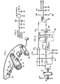
- apparatus for detecting a liquid-vapor change of phase in a fluid substance traveling through a conduit comprises a detector housing means or member 10 which provides a path of travel for the fluid and is interposed in a portion of the fluid-carrying conduit (not shown) in which the change of phase is to be detected.
- a source of radiation such as a light emitting diode (LED) 12 is disposed generally adjacent the housing means 10 for directing radiation into the path of travel therethrough.
- the housing means 10 is preferably provided with a suitable fitting or other means 14 which is, at least in part, transparent to the radiation produced by the source of radiation and, in the embodiment illustrated herein transparent to radiation in the infrared range produced by LED 12.
- a detector means or detector of radiation such as an infrared sensitive diode 16 (“photodiode”) or other similar transducer is placed at an opposite side of the path of travel from the source of radiation 12, such that the radiation from the source must pass through the fluid in the path of travel provided by housing 10 in order to reach the detector 16.
- the light sensitive diode or detector means 16 is responsive to the infrared electromagnetic radiation which reaches it for producing a corresponding electrical signal.
- a detector circuit or circuit means 20 is coupled in circuit for receiving this electrical signal produced by the detector means or diode 16 and is responsive thereto for providing a usable electrical signal for indicating a change of phase in the fluid flowing through the housing 10.
- this circuit means includes a differential peak detector circuit portion 22 which is coupled in circuit for providing a peak value signal corresponding to a peak value of the electrical signal produced at the transducer or detector means 16.
- the differential peak detector circuit portion 22 has a suitable time constant and operates into an open loop difference amplifier 24. Accordingly, it will be seen that the peak detector will provide a peak value signal corresponding generally to a peak value of the electrical signal produced by the detector or photodiode 16. The coupling with the difference amplifier results in the production of an output signal which will undergo an abrupt change in level in response to the peak value signal reaching or exceeding a predetermined level.
- a further band pass amplifier circuit 26 is interposed between the detector or photodiode 16 and the differential peak detector circuit 22.
- This will amplify the signal received at the differential peak detector and limit the pass band so as to focus on the desired detector signal and eliminate much of the background noise and other unwanted electrical interference. Accordingly, this circuit operates essentially to produce a "noise” output signal from detector 16 when bubbles pass through the conduit 10 and this "noise" signal is amplified, peak detected and, if above a certain level triggers an abrupt change in level of the output of amplifier 24.
- This abrupt change of level can be used to trigger or turn on other downstream equipment to form a suitable alarm, to drive a meter or give other suitable indication of the presence of bubbles, and hence of the start of a change from liquid to vapor state of the NH3.
- the pass band of band pass amplifier circuit 26 is on the order of 16 hertz to about 20 kilohertz. This approximate upper frequency will be defined essentially by the additional stray capacitance of this circuit, and is not a particularly critical limit.
- the infrared source is a light emitting diode of the type generally designated XL880C and the detector is a photodiode of the type generally designated SFH205 (Siemens).
- an additional output buffer amplifier circuit 28 is utilized to effectively buffer and interface the illustrated circuit from downstream circuitry, meters, alarms or other devices which the circuit is intended to operate in a given installation.
- the housing 10 comprises a tubular, open-ended member which has couplings or coupling means at respective ends thereof for interfitting with a fluid-carrying conduit.
- the coupling means 30, 32 comprise respective pipe threads such that the housing may be readily threaded in series in a conduit formed of similar pipe-threaded conduit members.
- Respective fittings or fitting means 40, 42 are located at generally diametrically opposed sides of the housing and are generally in diametrically opposed alignment with a transverse section through the housing. These fittings provide areas for mounting the LED 12 and photodiode 16, respectively.
- the photodiode 16 and LED 12 are preferably potted or otherwise enclosed in suitable environmentally protective housings of plastics material designated generally by reference numerals 44 and 46.
- These housings 44 and 46 are adapted to removably interfit over the respective fittings 40 and 42, in order to permit disassembly of these members for cleaning, if and as necessary.
- Additional mating fitting members 50, 52 are additionally provided which in turn receive the respective housings 44, 46 and interfit, preferably through mating machine screw threads, with fittings 40, 42.
- additional sealing means such as rubber O-rings or grommets 54, 56, are sealingly engaged between the respective fittings 40, 42 and 50, 52.
- These latter fittings 50, 52 are also constructed at least in part of a material which is transparent to the form of radiation utilized, and in the illustrated embodiment, this is electromagnetic radiation the infrared or near-visible spectrum. Accordingly, the fittings 50, 52 in effect define windows to the interior of the housing for said radiation to leave the LED and enter the photodiode, respectively.
Landscapes
- Physics & Mathematics (AREA)
- Biochemistry (AREA)
- Health & Medical Sciences (AREA)
- Life Sciences & Earth Sciences (AREA)
- Chemical & Material Sciences (AREA)
- Analytical Chemistry (AREA)
- Spectroscopy & Molecular Physics (AREA)
- General Health & Medical Sciences (AREA)
- General Physics & Mathematics (AREA)
- Immunology (AREA)
- Pathology (AREA)
- Investigating Or Analysing Materials By Optical Means (AREA)
- Investigating Or Analyzing Materials By The Use Of Electric Means (AREA)
Applications Claiming Priority (2)
| Application Number | Priority Date | Filing Date | Title |
|---|---|---|---|
| US233065 | 1988-08-17 | ||
| US07/233,065 US4931774A (en) | 1988-08-17 | 1988-08-17 | Liquid-vapor change of phase detector |
Publications (2)
| Publication Number | Publication Date |
|---|---|
| EP0364083A2 true EP0364083A2 (de) | 1990-04-18 |
| EP0364083A3 EP0364083A3 (de) | 1991-01-09 |
Family
ID=22875741
Family Applications (1)
| Application Number | Title | Priority Date | Filing Date |
|---|---|---|---|
| EP19890308215 Withdrawn EP0364083A3 (de) | 1988-08-17 | 1989-08-14 | Detektor zur Bestimmung der Phasenänderung eines Flüssigkeits-Dampf-Systems |
Country Status (6)
| Country | Link |
|---|---|
| US (1) | US4931774A (de) |
| EP (1) | EP0364083A3 (de) |
| AR (1) | AR241964A1 (de) |
| AU (1) | AU619880B2 (de) |
| BR (1) | BR8904116A (de) |
| CA (1) | CA1322582C (de) |
Cited By (2)
| Publication number | Priority date | Publication date | Assignee | Title |
|---|---|---|---|---|
| WO1991018280A1 (en) * | 1990-05-17 | 1991-11-28 | Roger George Jackson | Tomographic monitoring of fluid flows |
| EP0491552A3 (en) * | 1990-12-17 | 1992-08-26 | Sanden Corporation | Refrigerant charge detection system for an air conditioning system |
Families Citing this family (10)
| Publication number | Priority date | Publication date | Assignee | Title |
|---|---|---|---|---|
| US5475614A (en) * | 1994-01-13 | 1995-12-12 | Micro-Trak Systems, Inc. | Method and apparatus for controlling a variable fluid delivery system |
| US5574657A (en) * | 1994-02-08 | 1996-11-12 | Micro-Trak Systems, Inc. | Electronic rate meter controller and method |
| US5539386A (en) * | 1994-03-07 | 1996-07-23 | J-Kem Electronics, Inc. | Sensor for detecting air/liquid transitions in a transparent tubing |
| US6250130B1 (en) | 1995-07-10 | 2001-06-26 | Bayer Corporation | Method and apparatus for monitoring an aspirating and dispensing system |
| CA2177658A1 (en) * | 1995-07-10 | 1997-01-11 | Kurukundi Ramesh Murthy | Volume detection apparatus and method |
| AT403007B (de) * | 1995-07-24 | 1997-10-27 | Katschnig Helmut | Anlage zum erhitzen, desinfizieren und sterilisieren von gütern |
| WO2005038409A2 (en) * | 2003-10-17 | 2005-04-28 | Invensys Systems, Inc. | Flow assurance monitoring |
| US20060219941A1 (en) * | 2005-03-29 | 2006-10-05 | Clifford Edward T | Bubble type radiation detectors having automated read-out |
| US9482568B2 (en) * | 2013-09-03 | 2016-11-01 | Hadronex, Inc. | Detecting a sediment condition in a conduit |
| US20180224357A1 (en) * | 2017-01-17 | 2018-08-09 | Christopher James Hintz | Cavitation-induced equilibrium gas-phase spectrometry |
Family Cites Families (11)
| Publication number | Priority date | Publication date | Assignee | Title |
|---|---|---|---|---|
| US3544798A (en) * | 1968-04-16 | 1970-12-01 | Bowser Inc | Radiation sensitive device for detecting interface between fluids |
| US3810695A (en) * | 1972-12-14 | 1974-05-14 | Gam Rad | Fluid analyzer with variable light path |
| CH627272A5 (en) * | 1976-10-11 | 1981-12-31 | Gerhard Lauer | Device for determining the optical transparency of a flowing medium |
| FR2396305A1 (fr) * | 1977-06-28 | 1979-01-26 | Charbonnages Ste Chimique | Detecteur de mouvement et, notamment, de surveillance de personnes |
| AT357348B (de) * | 1977-09-20 | 1980-07-10 | Inst Cercetari Moderniza | Opazitaetsmessgeraet zur bestimmung der anwesen- heit fester, undurchsichtiger, in einem durch- sichtigen medium ungleichmaessig verteilter partikel |
| US4251809A (en) * | 1979-02-16 | 1981-02-17 | Alco Standard Corporation | Method and apparatus for detecting the presence of water in oil |
| DE3406176A1 (de) * | 1983-04-28 | 1984-10-31 | Philips Patentverwaltung Gmbh, 2000 Hamburg | Anordnung zum pruefen einer fluessigkeit auf beimengungen |
| US4631529A (en) * | 1984-10-17 | 1986-12-23 | Ivek Corporation | Electro-optical fluid detector |
| US4658244A (en) * | 1985-03-28 | 1987-04-14 | Imed Corporation | Air-in-line detector |
| US4713547A (en) * | 1986-01-03 | 1987-12-15 | Gte Products Corporation | Method and apparatus for monitoring the flow of mercury in a system |
| US4816695A (en) * | 1987-08-31 | 1989-03-28 | Lavin Thomas N | Optical fluid detector |
-
1988
- 1988-08-17 US US07/233,065 patent/US4931774A/en not_active Expired - Fee Related
-
1989
- 1989-08-14 EP EP19890308215 patent/EP0364083A3/de not_active Withdrawn
- 1989-08-16 CA CA000608545A patent/CA1322582C/en not_active Expired - Fee Related
- 1989-08-16 BR BR898904116A patent/BR8904116A/pt not_active IP Right Cessation
- 1989-08-16 AU AU39926/89A patent/AU619880B2/en not_active Ceased
- 1989-08-17 AR AR89314684A patent/AR241964A1/es active
Cited By (2)
| Publication number | Priority date | Publication date | Assignee | Title |
|---|---|---|---|---|
| WO1991018280A1 (en) * | 1990-05-17 | 1991-11-28 | Roger George Jackson | Tomographic monitoring of fluid flows |
| EP0491552A3 (en) * | 1990-12-17 | 1992-08-26 | Sanden Corporation | Refrigerant charge detection system for an air conditioning system |
Also Published As
| Publication number | Publication date |
|---|---|
| EP0364083A3 (de) | 1991-01-09 |
| BR8904116A (pt) | 1990-04-10 |
| AU619880B2 (en) | 1992-02-06 |
| AR241964A1 (es) | 1993-01-29 |
| US4931774A (en) | 1990-06-05 |
| CA1322582C (en) | 1993-09-28 |
| AU3992689A (en) | 1990-02-22 |
Similar Documents
| Publication | Publication Date | Title |
|---|---|---|
| US4931774A (en) | Liquid-vapor change of phase detector | |
| US5315862A (en) | Flow meter | |
| DE19882239B3 (de) | Wirbel-Durchflußmesser mit Signalverarbeitung | |
| US6487916B1 (en) | Ultrasonic flow metering system | |
| EP0511651B1 (de) | Rohreinbau-Fluidüberwachungssystem und Verfahren | |
| US6208255B1 (en) | Non-resonant electromagnetic energy sensor | |
| AU648928B2 (en) | Monitoring film fouling in a process stream | |
| US3958449A (en) | Process and apparatus for testing pipelines for leaks | |
| US6401525B1 (en) | Leak detection in liquid carrying conduits | |
| US20020170362A1 (en) | Method and apparatus for flow control of NH3 | |
| US4170135A (en) | Coaxial cavity for measuring level of liquid in a container | |
| CN103558179A (zh) | 一种测量管道内气液两相流的截面相含率的装置及方法 | |
| CN109283090A (zh) | 热力循环系统水中不溶物含量在线检测装置及方法 | |
| US5459568A (en) | Concentration measuring apparatus | |
| US6346888B1 (en) | Non-resonant electromagnetic energy sensor | |
| US11187661B2 (en) | Detecting black powder levels in flow-lines | |
| US5798699A (en) | Method for monitoring and selectively sampling a fluid flow stream | |
| CA2001030C (en) | Method and apparatus for measuring entrained gas bubble content of flowing fluid | |
| US4347747A (en) | Single phase flow measurement | |
| US4664772A (en) | Insertion probe system for continuous measurement of pH level in process lines | |
| US9696192B2 (en) | In-line flow meter | |
| CN113932866A (zh) | 一种管道内密度不固定的流体质量流量测量系统及其方法 | |
| Tinham et al. | Biofouling assessment using an infrared monitor | |
| JP2733717B2 (ja) | 二相流流量計 | |
| US4450712A (en) | Pulp consistancy measurement |
Legal Events
| Date | Code | Title | Description |
|---|---|---|---|
| PUAI | Public reference made under article 153(3) epc to a published international application that has entered the european phase |
Free format text: ORIGINAL CODE: 0009012 |
|
| AK | Designated contracting states |
Kind code of ref document: A2 Designated state(s): DE ES FR GB IT |
|
| PUAL | Search report despatched |
Free format text: ORIGINAL CODE: 0009013 |
|
| AK | Designated contracting states |
Kind code of ref document: A3 Designated state(s): DE ES FR GB IT |
|
| RHK1 | Main classification (correction) |
Ipc: G01N 21/59 |
|
| 17P | Request for examination filed |
Effective date: 19910703 |
|
| 17Q | First examination report despatched |
Effective date: 19930115 |
|
| STAA | Information on the status of an ep patent application or granted ep patent |
Free format text: STATUS: THE APPLICATION IS DEEMED TO BE WITHDRAWN |
|
| 18D | Application deemed to be withdrawn |
Effective date: 19950715 |