EP0364088A2 - Calibrage du diamètre d'une roue pour véhicule de chemin de fer - Google Patents
Calibrage du diamètre d'une roue pour véhicule de chemin de fer Download PDFInfo
- Publication number
- EP0364088A2 EP0364088A2 EP89308456A EP89308456A EP0364088A2 EP 0364088 A2 EP0364088 A2 EP 0364088A2 EP 89308456 A EP89308456 A EP 89308456A EP 89308456 A EP89308456 A EP 89308456A EP 0364088 A2 EP0364088 A2 EP 0364088A2
- Authority
- EP
- European Patent Office
- Prior art keywords
- tachometer
- vehicle
- track
- pulses
- detection
- Prior art date
- Legal status (The legal status is an assumption and is not a legal conclusion. Google has not performed a legal analysis and makes no representation as to the accuracy of the status listed.)
- Withdrawn
Links
- 238000001514 detection method Methods 0.000 claims abstract description 14
- 230000001419 dependent effect Effects 0.000 claims abstract description 4
- 230000004044 response Effects 0.000 claims abstract description 3
- 238000012937 correction Methods 0.000 description 4
- 238000012423 maintenance Methods 0.000 description 3
- 238000005096 rolling process Methods 0.000 description 3
- 230000001939 inductive effect Effects 0.000 description 2
- 230000001133 acceleration Effects 0.000 description 1
- 238000004891 communication Methods 0.000 description 1
- 239000013078 crystal Substances 0.000 description 1
- 238000013481 data capture Methods 0.000 description 1
- 230000006866 deterioration Effects 0.000 description 1
- 238000011161 development Methods 0.000 description 1
- 238000010586 diagram Methods 0.000 description 1
- 238000002955 isolation Methods 0.000 description 1
- 238000005259 measurement Methods 0.000 description 1
- 238000000034 method Methods 0.000 description 1
- 238000012544 monitoring process Methods 0.000 description 1
Images


Classifications
-
- B—PERFORMING OPERATIONS; TRANSPORTING
- B61—RAILWAYS
- B61L—GUIDING RAILWAY TRAFFIC; ENSURING THE SAFETY OF RAILWAY TRAFFIC
- B61L25/00—Recording or indicating positions or identities of vehicles or trains or setting of track apparatus
- B61L25/02—Indicating or recording positions or identities of vehicles or trains
- B61L25/026—Relative localisation, e.g. using odometer
-
- B—PERFORMING OPERATIONS; TRANSPORTING
- B61—RAILWAYS
- B61L—GUIDING RAILWAY TRAFFIC; ENSURING THE SAFETY OF RAILWAY TRAFFIC
- B61L25/00—Recording or indicating positions or identities of vehicles or trains or setting of track apparatus
- B61L25/02—Indicating or recording positions or identities of vehicles or trains
- B61L25/021—Measuring and recording of train speed
-
- G—PHYSICS
- G01—MEASURING; TESTING
- G01P—MEASURING LINEAR OR ANGULAR SPEED, ACCELERATION, DECELERATION, OR SHOCK; INDICATING PRESENCE, ABSENCE, OR DIRECTION, OF MOVEMENT
- G01P21/00—Testing or calibrating of apparatus or devices covered by the preceding groups
- G01P21/02—Testing or calibrating of apparatus or devices covered by the preceding groups of speedometers
Definitions
- the present invention relates to wheel diameter calibration for a railway vehicle.
- the present invention may be applied to the automatic correction of the output counts of a tachometer of a railway vehicle in order that speed and/or distance may be accurately calculated with correction for changes in wheel diameter due to wheel wear and wheel turning.
- a tachometer attached to an axle of a railway vehicle has been used with manually settable correction for wheel diameter, in order to display speed to the driver of such a vehicle, and the correction setting is only adjusted when the wheels of a particular axle associated with the tachometer have been removed from the vehicle for maintenance purposes, or for turning down to remove flats due to wheelslide.
- Modern railway rolling stock is being designed to incorporate advanced microprocessor based control and data capture systems working in association with a through-train data bus communication network to control passenger information and driver advisory equipment.
- Such systems require precise positional data, which have previously been provided by means of trackside transponders or inductive loops.
- the provision of such devices is expensive in both capital and maintenance costs, and does not meet the requirement for flexibility necessitated by such as temporary speed restrictions, and schedule changes, or for the precise position recording of fault or unusual events.
- a solution to the above difficulties would be a distance measuring device driven by a wheel tachometer with an accuracy at least two orders of magnitude better than available from current equipment.
- a railway system comprising:-
- the system includes a third such device in or adjacent the track, the second device being intermediate the first and third devices and the distance between the point of detection by said detecting means of the second device and the point of detection by said detecting means of said third device being the same as said known distance, said deriving means being arranged for deriving said count from the mean of the number of pulses from the tachometer between detecting the first and second devices and the number of pulses from the tachometer between detecting the second and third devices.
- Each of said devices could comprise an infra-red beam emitting beacon, said detecting means comprising infra-red detecting means.
- each of the beacons emits at least two infra-red beams, spaced one above the other and meeting substantially at said detecting means in use of system.
- reference numerals 1 and 2 denote two vehicles of a railway train travelling in the direction of the arrow.
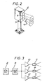
- a driver's cab DC At each end of each of vehicles 1 and 2 is a driver's cab DC, each cab having an infra-red detector 3 and a control unit 4, the unit 4 in the forward cab of the leading vehicle (1) being used as a master unit.
- Three trackside beacons A, B and C are provided, with a clearance between each beacon and the train of approximately 500 millimetres, with a distance between beacons A and B of 100 metres and with a distance between beacons B and C of 100 metres.
- each of beacons A, B and C has three infra-red emitters 5, 6 and 7 disposed one above the other and producing three narrow infra-red beams such that the edges of the upper and lower beams meet at the clearance distance to be detected by the detector 3 in the forward cab of the leading vehicle, to produce at the detector a narrow beam in the direction of travel of the train but a beam which is wide enough in the vertical direction to compensate for variations in detector height due to vehicle loading or rolling. Also, this provides for a protection against failure of a single emitter. Typically, each emitter has a beam angle of 10 o .
- each of the emitters 5, 6 and 7 is pulsed with a 10% active output at a fixed frequency in the range from 10kHz to 50kHz in order to provide greater output power from the emitter during the 10% on period.
- This is achieved in each beacon by a crystal oscillator 8 whose output feeds a pulse generator 9 (derived using a Johnson counter) the output of which feeds the emitters 5, 6 and 7 via amplifiers 10, 11 and 12 respectively.
- the output of pulse generator 9 is shown in Figure 4a) and the output of oscillator 8 is shown in Figure 4b).
- the emitter outputs are modulated at a frequency which is one tenth of the frequency of oscillator 8 and, typically, the modulation frequency for beacon A is 10kHz, the modulation frequency for beacon B is 13kHz and the modulation frequency for beacon C is 16kHz.
- each wheel tachometer 13 of a vehicle is coupled via an isolation transformer 14, a signal amplifier 15 and a low pass filter 16 to a 16-bit counter 17 in the control unit 4 of the vehicle.
- the output of each detector 3 is connected via a signal amplifier 18 and a band-pass filter 19 to the input of a gate latch 20 in the associated control unit 4.
- One output of the latch 20 is fed to a priority interrupt controller 21 (whose output is connected to a microprocessor 22), another output of latch 20 being connected to an input of an AND gate 23, the other input of which is connected to an output of a 1MHz clock 24.
- the output of AND gate 23 is fed to an input of a 16-bit counter 25 whose output is fed to another input of the controller 21.
- Reference numeral 27 denotes an erasable programmable read only memory (EPROM)
- reference numeral 28 denotes an address and control bus
- reference numeral 29 denotes a data bus which, for controlling the train, carries "speed set and coasting advisory" information.
- Reference numeral 30 denotes a train data bus controller which interfaces via a bus 31 with the train management system, the controller 30 being provided with a train data bus port 32 connected via a train data bus 33 to slave controllers of the train.
- the detector 3 in the forward cab of the leading vehicle produces a resultant output signal which is amplified in amplifier 18 and filtered in filter 19 to eliminate spurious triggering.
- the frequency is checked within the band pass limits, and then the number of pulses received within a given gate period, say 5mS, are counted.
- the detector system is interrogated by the microprocessor 22 at the termination of the gate period and the resultant count then compared with a look-up table in the microprocessor memory.
- the controlling microprocessor 22 in the unit 4 of the forward cab of the leading vehicle will instruct, by means of the train data bus 33, all other controllers on the train to start counting incoming tachometer wheel pulses until a further valid wheel calibration emitter beacon frequency is detected, at which point the count from the first beacon (C) to the second beacon (B) will be stored by the system, and a second count started between the second beacon (B) and the third beacon (A). The two results will then be totalled and divided by two to provide a mean tachometer pulse count over the nominal inter-beacon distance of 100 metres.
- the three beacons are modulated at different frequencies within the overall bandwidth of the band-pass filter 19 so that the train equipment will be able to identify each of the three beacons.
- it will be possible to calibrate between any two remaining beacons, and at the same time provide a fault report to be logged in an on train data monitor, but more importantly, it will permit health monitoring of the beacons to detect deterioration in performance, and raise a fault report before complete failure occurs.
- one half of the count between beacons C and A, or the count between beacons B and A or the count between beacons C and B could be used.
- the tachometer would generate a known pulse count per nominal metre of wheel circumference, say 200 pulses per metre. With the beacons accurately positioned at 100 metre intervals, then if the wheels were on nominal diameter, the tachometer would generate 20,000 pulses between detecting the first beacon (C) and the second (B). If the wheels of the axle to which the tachometer is fitted are small by 1%, then the number of pulses generated between the beacons would be 20,200 and any speed and/or distance measurement, and/or assumed value of wheel diameter, and/or actual tachometer pulse count would be reduced by multiplying by a factor equal to:
- each tachometer on the train it is necessary for each tachometer on the train to be calibrated independently as wheel diameters on different axles may vary considerably, and using the train data bus 33 to initiate the count on each tachometer means that only the infra-red detector 4 in the controlling vehicle will have to be powered up, and will only have to be fitted to one side of the vehicle, with the emitter beacons and the detector always on the same side of the track.
- Data related to the wheel diameter compensation factor will be recorded in an on train monitor recorder each time the unit is powered up, and each time a wheel diameter calibration takes place. This information will enable wheel diameters to be monitored for maintenance purposes, and also to ensure that the calibration is consistent.
- infra-red beacon system As an alternative to the infra-red beacon system described above, it would also be possible to use inductive loops as beacons, or ultra-sonic transponders, but in either case it would be necessary to increase the inter-beacon distance by a factor of ten to ensure that the detection distance variation possible with either of these alternatives would bear the same proportion to the total inter-beacon count as a narrow infra-red beam.
Landscapes
- Engineering & Computer Science (AREA)
- Mechanical Engineering (AREA)
- Physics & Mathematics (AREA)
- General Physics & Mathematics (AREA)
- Electric Propulsion And Braking For Vehicles (AREA)
Applications Claiming Priority (2)
| Application Number | Priority Date | Filing Date | Title |
|---|---|---|---|
| GB8821125A GB2223588B (en) | 1988-09-09 | 1988-09-09 | Wheel diameter calibration for a railway vehicle |
| GB8821125 | 1988-09-09 |
Publications (2)
| Publication Number | Publication Date |
|---|---|
| EP0364088A2 true EP0364088A2 (fr) | 1990-04-18 |
| EP0364088A3 EP0364088A3 (fr) | 1990-10-31 |
Family
ID=10643288
Family Applications (1)
| Application Number | Title | Priority Date | Filing Date |
|---|---|---|---|
| EP19890308456 Withdrawn EP0364088A3 (fr) | 1988-09-09 | 1989-08-21 | Calibrage du diamètre d'une roue pour véhicule de chemin de fer |
Country Status (3)
| Country | Link |
|---|---|
| EP (1) | EP0364088A3 (fr) |
| CA (1) | CA1326964C (fr) |
| GB (1) | GB2223588B (fr) |
Cited By (9)
| Publication number | Priority date | Publication date | Assignee | Title |
|---|---|---|---|---|
| DE19736712C1 (de) * | 1997-08-18 | 1999-02-11 | Siemens Ag | Verfahren zum Kalibrieren einer Geschwindigkeitsmeßanlage |
| GB2328749A (en) * | 1997-08-29 | 1999-03-03 | Tvi Europ Ltd | A method for calibrating a speed or distance measuring device |
| US6148269A (en) * | 1998-07-20 | 2000-11-14 | General Electric Company | Wheel diameter calibration system for vehicle slip/slide control |
| WO2010046172A1 (fr) * | 2008-10-23 | 2010-04-29 | Siemens Aktiengesellschaft | Procédé de réalisation d'un essai de roulement d'un véhicule ferroviaire et dispositif de commande correspondant |
| WO2015147659A1 (fr) * | 2014-03-26 | 2015-10-01 | Amateo Sp. Z.O.O. | Système d'identification d'objet irid |
| CN105899908A (zh) * | 2013-11-12 | 2016-08-24 | 泰雷兹加拿大公司 | 动态轮径确定系统和方法 |
| CN106598041A (zh) * | 2015-10-20 | 2017-04-26 | 沈阳新松机器人自动化股份有限公司 | 带有轮径校正功能的双轮差动底盘控制装置及其控制方法 |
| DE102016200436A1 (de) | 2016-01-15 | 2017-07-20 | Siemens Aktiengesellschaft | Verfahren und Vorrichtung zur automatischen Kalibrierung eines Messsensors einer angetriebenen Achse eines Schienenfahrzeugs |
| GB2633069A (en) * | 2023-08-31 | 2025-03-05 | Siemens Mobility Ltd | Method of calibrating an onboard computer installed in a rail vehicle |
Families Citing this family (1)
| Publication number | Priority date | Publication date | Assignee | Title |
|---|---|---|---|---|
| US5377127A (en) * | 1993-11-15 | 1994-12-27 | Ford Motor Company | Software calibration of speed sensors |
Family Cites Families (4)
| Publication number | Priority date | Publication date | Assignee | Title |
|---|---|---|---|---|
| CH351127A (de) * | 1957-02-26 | 1960-12-31 | Westinghouse Bremsen Und Signa | Verfahren und Apparat zur Messung der Geschwindigkeit von vorbeifahrenden Fahrzeugen |
| DE1248091B (de) * | 1964-04-28 | 1967-08-24 | Siemens Ag | Einrichtung in einem Fahrzeuggeraet fuer Anlagen zur linienfoermigen Zugbeeinflussung |
| GB1335985A (en) * | 1970-10-06 | 1973-10-31 | Secretary Environment Brit | Vehicle control apparatus |
| DE3044503A1 (de) * | 1980-11-22 | 1982-06-03 | Licentia Patent-Verwaltungs-Gmbh, 6000 Frankfurt | "einrichtung zur automatischen eichung von wegmessvorrichtungen" |
-
1988
- 1988-09-09 GB GB8821125A patent/GB2223588B/en not_active Expired - Lifetime
-
1989
- 1989-08-21 EP EP19890308456 patent/EP0364088A3/fr not_active Withdrawn
- 1989-08-24 CA CA 609261 patent/CA1326964C/fr not_active Expired - Fee Related
Cited By (11)
| Publication number | Priority date | Publication date | Assignee | Title |
|---|---|---|---|---|
| DE19736712C1 (de) * | 1997-08-18 | 1999-02-11 | Siemens Ag | Verfahren zum Kalibrieren einer Geschwindigkeitsmeßanlage |
| GB2328749A (en) * | 1997-08-29 | 1999-03-03 | Tvi Europ Ltd | A method for calibrating a speed or distance measuring device |
| GB2328749B (en) * | 1997-08-29 | 2001-05-09 | Tvi Europ Ltd | A method for calibrating a speed or distance measuring device |
| US6148269A (en) * | 1998-07-20 | 2000-11-14 | General Electric Company | Wheel diameter calibration system for vehicle slip/slide control |
| WO2010046172A1 (fr) * | 2008-10-23 | 2010-04-29 | Siemens Aktiengesellschaft | Procédé de réalisation d'un essai de roulement d'un véhicule ferroviaire et dispositif de commande correspondant |
| CN105899908A (zh) * | 2013-11-12 | 2016-08-24 | 泰雷兹加拿大公司 | 动态轮径确定系统和方法 |
| US9469318B2 (en) | 2013-11-12 | 2016-10-18 | Thales Canada Inc | Dynamic wheel diameter determination system and method |
| WO2015147659A1 (fr) * | 2014-03-26 | 2015-10-01 | Amateo Sp. Z.O.O. | Système d'identification d'objet irid |
| CN106598041A (zh) * | 2015-10-20 | 2017-04-26 | 沈阳新松机器人自动化股份有限公司 | 带有轮径校正功能的双轮差动底盘控制装置及其控制方法 |
| DE102016200436A1 (de) | 2016-01-15 | 2017-07-20 | Siemens Aktiengesellschaft | Verfahren und Vorrichtung zur automatischen Kalibrierung eines Messsensors einer angetriebenen Achse eines Schienenfahrzeugs |
| GB2633069A (en) * | 2023-08-31 | 2025-03-05 | Siemens Mobility Ltd | Method of calibrating an onboard computer installed in a rail vehicle |
Also Published As
| Publication number | Publication date |
|---|---|
| GB2223588A (en) | 1990-04-11 |
| GB8821125D0 (en) | 1988-10-12 |
| EP0364088A3 (fr) | 1990-10-31 |
| GB2223588B (en) | 1992-01-29 |
| CA1326964C (fr) | 1994-02-15 |
Similar Documents
| Publication | Publication Date | Title |
|---|---|---|
| DD292880A5 (de) | Steuerungssystem fuer die abfolge mehrerer eisenbahnzuege auf einem netz | |
| AU635687B2 (en) | Method and apparatus for verification of rail braking distances | |
| CA2102140C (fr) | Systeme fixe de surveillance de l'angle d'attaque des roues de wagon de chemin de fer | |
| EP0204817B1 (fr) | Mesure des charges transmises par des roues de vehicules | |
| EP0364088A2 (fr) | Calibrage du diamètre d'une roue pour véhicule de chemin de fer | |
| US3772640A (en) | Vehicle control system with vehicle location error checking means | |
| GB1565520A (en) | Slip-slide detector system for railway car wheels | |
| CA1168726A (fr) | Detecteur de roue de materiel roulant ferroviaire | |
| EP0715579B1 (fr) | Systeme de liberation de l'ouverture des portes de vehicules sur rails | |
| JP3082002B2 (ja) | 鉄道車輪踏面の異常検出装置 | |
| DE19729990A1 (de) | Verfahren und Vorrichtung zur Bestimmung der zurückgelegten Wegstrecke und der Geschwindigkeit von Schienenfahrzeugen | |
| EP3495847B1 (fr) | Agencement de tachygraphe et procédé de fonctionnement d'un agencement de tachygraphe | |
| US4274611A (en) | Device for the detection of the position of a railway vehicle | |
| RU2560211C1 (ru) | Способ и устройство управления для определения длины по меньшей мере одного участка пути | |
| DE3720653A1 (de) | Verfahren und vorrichtung zur geschwindigkeitsmessung von fahrzeugen | |
| JP2665481B2 (ja) | 連続位置検知による列車長検出方法 | |
| RU2000979C1 (ru) | Способ идентификации поездов | |
| JPS62254607A (ja) | 列車の自動運転装置 | |
| AU686258B2 (en) | Wayside monitoring of the angle-of-attack of railway vehicle wheelsets | |
| JPH0775205A (ja) | 速度照査装置 | |
| JP3903218B2 (ja) | 保守用車の事故防止装置 | |
| JP2925288B2 (ja) | 列車位置検出装置及びその装置を用いた列車制御方式 | |
| AT400028B (de) | Einrichtung zur adaptiven beeinflussung eines motoriebenen vehikels | |
| SU658017A1 (ru) | Устройство дл автоматического управлени торможением поезда | |
| GB1347013A (en) | Mobile rail mounted machine for carrying out railway track work at intervals along the track |
Legal Events
| Date | Code | Title | Description |
|---|---|---|---|
| PUAI | Public reference made under article 153(3) epc to a published international application that has entered the european phase |
Free format text: ORIGINAL CODE: 0009012 |
|
| AK | Designated contracting states |
Kind code of ref document: A2 Designated state(s): BE DE ES FR IT |
|
| PUAL | Search report despatched |
Free format text: ORIGINAL CODE: 0009013 |
|
| AK | Designated contracting states |
Kind code of ref document: A3 Designated state(s): BE DE ES FR IT |
|
| STAA | Information on the status of an ep patent application or granted ep patent |
Free format text: STATUS: THE APPLICATION IS DEEMED TO BE WITHDRAWN |
|
| 18D | Application deemed to be withdrawn |
Effective date: 19910503 |