EP0364101A2 - Méthode de formation d'une jonction Josephson de type liaison faible et dispositif supraconducteur utilisant la jonction - Google Patents
Méthode de formation d'une jonction Josephson de type liaison faible et dispositif supraconducteur utilisant la jonction Download PDFInfo
- Publication number
- EP0364101A2 EP0364101A2 EP89309231A EP89309231A EP0364101A2 EP 0364101 A2 EP0364101 A2 EP 0364101A2 EP 89309231 A EP89309231 A EP 89309231A EP 89309231 A EP89309231 A EP 89309231A EP 0364101 A2 EP0364101 A2 EP 0364101A2
- Authority
- EP
- European Patent Office
- Prior art keywords
- substrate
- thin film
- weak
- film
- grain boundary
- Prior art date
- Legal status (The legal status is an assumption and is not a legal conclusion. Google has not performed a legal analysis and makes no representation as to the accuracy of the status listed.)
- Granted
Links
Images


Classifications
-
- H—ELECTRICITY
- H10—SEMICONDUCTOR DEVICES; ELECTRIC SOLID-STATE DEVICES NOT OTHERWISE PROVIDED FOR
- H10N—ELECTRIC SOLID-STATE DEVICES NOT OTHERWISE PROVIDED FOR
- H10N60/00—Superconducting devices
- H10N60/01—Manufacture or treatment
- H10N60/0912—Manufacture or treatment of Josephson-effect devices
- H10N60/0941—Manufacture or treatment of Josephson-effect devices comprising high-Tc ceramic materials
-
- Y—GENERAL TAGGING OF NEW TECHNOLOGICAL DEVELOPMENTS; GENERAL TAGGING OF CROSS-SECTIONAL TECHNOLOGIES SPANNING OVER SEVERAL SECTIONS OF THE IPC; TECHNICAL SUBJECTS COVERED BY FORMER USPC CROSS-REFERENCE ART COLLECTIONS [XRACs] AND DIGESTS
- Y10—TECHNICAL SUBJECTS COVERED BY FORMER USPC
- Y10S—TECHNICAL SUBJECTS COVERED BY FORMER USPC CROSS-REFERENCE ART COLLECTIONS [XRACs] AND DIGESTS
- Y10S505/00—Superconductor technology: apparatus, material, process
- Y10S505/70—High TC, above 30 k, superconducting device, article, or structured stock
- Y10S505/701—Coated or thin film device, i.e. active or passive
- Y10S505/702—Josephson junction present
-
- Y—GENERAL TAGGING OF NEW TECHNOLOGICAL DEVELOPMENTS; GENERAL TAGGING OF CROSS-SECTIONAL TECHNOLOGIES SPANNING OVER SEVERAL SECTIONS OF THE IPC; TECHNICAL SUBJECTS COVERED BY FORMER USPC CROSS-REFERENCE ART COLLECTIONS [XRACs] AND DIGESTS
- Y10—TECHNICAL SUBJECTS COVERED BY FORMER USPC
- Y10S—TECHNICAL SUBJECTS COVERED BY FORMER USPC CROSS-REFERENCE ART COLLECTIONS [XRACs] AND DIGESTS
- Y10S505/00—Superconductor technology: apparatus, material, process
- Y10S505/725—Process of making or treating high tc, above 30 k, superconducting shaped material, article, or device
- Y10S505/729—Growing single crystal, e.g. epitaxy, bulk
Definitions
- the present invention relates to a method of forming a Josephson junction particularly a weak-link junction, of oxide superconductor, and also to a superconducting device employing the junction.
- the insulating layer must be made thinner than in the conventional case, and (2) in order to obtain thin superconductor films of high Tc, the films must be formed under the condition of a high substrate temperature or must be annealed at high temperatures.
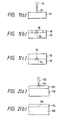
- the oxide superconductor is prone to react with insulating materials (in general, oxides) and is therefore very difficult of forming the tunneling type Josephson junction. For these reasons, Josephson junctions have heretofore been obtained only when a bar 10 of superconductor ceramics is pressed against the superconductor 11 as shown in Fig. 14, and a Josephson junction in the form of layered films has not been fabricated.
- a practicable method of forming the weak link is one wherein, as shown in Fig. 15, a substrate 20 is provided with a step 21, and the thickness of the thin superconducting film 22 formed thereon is changed.
- a method wherein hydrogen ions are implanted, thereby causing the superconducting current to flow through only the narrow region a method wherein grain boundaries are utilized, and so forth. Examples of the method which utilizes the grain boundaries are described in Phys. Rev. Lett. 60 (1988) 1653 and the official gazette of Japanese Patent Application Laid-open No. 273782/1987.
- the prior-art method of forming a weak-link Josephson junction by the use of a thin film of oxide superconductor is difficult of forming weak-link Josephson junctions of uniform characteristics at a predetermined position, and has been problematic in point of reliability.
- An object of the present invention is to reproducibly form the weak-link Josephson junctions of uniform characteristics at the predetermined position.
- Another object is to fabricate a superconducting device by the use of the weak-link Josephson junction thus formed.
- the present invention utilizes as the weak-link Josephson junction a crystal grain boundary which is produced reflecting an artificial crystalline defect.
- atoms of different species from a superconducting material are deposited on a substrate, or the surface of a substrate is disturbed.
- a thin film is epitaxially grown on the substrate.
- An ion beam which is accelerated and focused is used as means for the deposition or destruction.
- Figs. 1(a) - 1(c) The concrete operation of this expedient will be described in conjunction with Figs. 1(a) - 1(c).
- the metal is deposited or a damaged layer 32 is formed down to a depth of about 100 - 200 ⁇ below the surface of the substrate 30, in accordance with the magnitude of the acceleration voltage of the ion beam 31 (Fig. 1(a)).
- the width of the deposited region or damaged region can be changed by the way of focusing the ion beam 31, and can be made 1 ⁇ m or less.
- the thickness of the deposited matter is determined by an ion dose and a beam width.
- the deposited matter comes to have a thickness of 39 ⁇ .
- the substrate 30 thus processed is formed with a superconducting thin film 33 under the condition of epitaxial growth. Then, on regions not subjected to the deposition or damages, the superconducting thin film 33 is epitaxially grown, whereas on the region 34 processed by the ion beam 31, the epitaxial growth is hindered, and microcrystals 35 are produced (Fig. 1(b)).
- the film 33 thickens, crystals which have grown from both the sides of the region 34 processed by the ion beam 31 collide against each other.
- a superconducting thin film epitaxially grown on a substrate is diffused with atoms of different species which hinders a superconducting current from flowing, or it has the vicinity of its surface disturbed, and the resultant superconducting thin film is annealed, thereby to form a crystal grain boundary.
- An ion beam which is accelerated and focused is used as means for the diffusion or damaging.
- Still another expedient is as follows: A part of different crystal plane orientation is artificially formed on a substrate, and superconducting thin films of different growth orientations are epitaxially grown on the substrate, whereby a crystal grain boundary which hinders a superconducting current from flowing is formed on the part of the substrate at which the crystal face orientations thereof have been changed.
- Oxide superconductor materials formulated by Ln1Ba2Cu3O y (where Ln denotes a rare-earth metal such as Y, Er or Ho) have an orthorhombic perovskite structure, the a-axis, b-axis and c-axis of which have lengths of 3.83 ⁇ , 3.89 ⁇ and 11.7 ⁇ , respectively.
- Tc critical temperature
- Jc critical current density
- the oxide-superconductor thin-film material undergoes a high temperature process of 600 °C - 950 °C in a film forming process, a material having a low reactivity with the thin films needs to be selected as the substrate material.
- a substrate having few crystal grain boundaries and facilitating epitaxial growth needs to be selected.
- the substrate materials which are desirable from these viewpoints are strontium titanate (SrTiO3), magnesium oxide (MgO), zirconium dioxide (ZrO2), etc.
- the growth directions of thein film crystals differ depending upon the kinds of substrate materials and the crystal plane orientations of substrates.
- the thin film of the oxide superconductor is formed on the substrate of MgO (100) or ZrO2 (100)
- the lattice constants of the substrate and the a- and b-axes of the thin film mismatch greatly, and hence, the film whose c-plane, most stable in term of energy, lies in contact with the plane of the substrate, is formed.
- the lattice constant (3.90 ⁇ ) of SrTiO3 is substantially equal to the lattice constant of the b-axis or the length of 1/3 of c-axis of the oxide-superconductor thin film, and hence, the oxide-superconductor thin film is epitaxially grown on the substrate into an a-axis oriented one.
- an oxide-superconductor thin film oriented in the direction (110) is formed on a substrate of SrTiO3 (110).
- the off angle ⁇ should desirably be 0.5 degree or more. Besides, similar effects are attained even when SrTiO3 (110), SrTiO3 (111), MgO and ZrO2 substrates are employed.
- SrTiO3 110
- SrTiO3 111
- MgO magnesium
- ZrO2 substrates magnesium
- Example 1 of the present invention will be described with reference to Figs. 4(a) - 4(c).
- gallium (Ga) 41 was irradiated in the form of lines in directions [011] and [001] by a focused ion beam (FIB) method.
- the conditions of the projection were an acceleration voltage of 30 kV, a line width of 1 ⁇ m (measured by SIM: scanning ion microscopy), and a line length of 0.5 mm.
- the doses of the Ga were 5 x 10¹¹ - 5 x 10¹⁸ /cm2, and were changed one order in succession.
- the eight lines 42 of the respective doses were formed at intervals of 3 mm.
- a thin film of ErBa2Cu3O 7- ⁇ 44 was formed by sputtering.
- the temperature of the substrate 43 was held at 700 °C during the formation of the film 44.
- the thickness of the film 44 was 0.7 ⁇ m.
- linear defects were noted in correspondence with the places irradiated with the Ga ions. Exactly, the linear defects were observed in correspondence with the five lines whose doses were 5 x 10¹⁴ /cm2 or above.
- the film 44 was annealed in oxygen at 830 °C for 2 hours. The linear defects, namely, grain boundaries 45 became clear after the annealing.
- the parts of the superconducting film 44 at both the ends of the grain boundary 45 were removed to form the neck portion of this superconducting film, and the I - V characteristic of the grain boundary 45 was measured by a conventional four-probe method.
- the I - V curve exhibited the feature of a superconductivity.
- a critical current density at 77 K in a region having no grain boundary was 2 x 10⁴ A/cm2.
- Example 1 Using a substrate which was irradiated with ions under the same conditions as in Example 1, a thin film of ErBa2Cu3O 7- ⁇ was formed thereon by sputtering. Conditions for the film formation were the same as in Example 1 except for a film thickness of 3500 ⁇ . In the film which was annealed in oxygen at 830 °C for 2 hours, grain boundaries were observed in correspondence with seven lines whose doses were 5 x 10¹² /cm2 or above. As in the case of Example 1, the I - V characteristics of the grain boundaries were investigated by the conventional four-probe method. The film of Example 1 had a critical temperature (Tc) as high as 88 K, but the temperature Tc of the film being 3500 ⁇ thick lowered to 83 K.
- Tc critical temperature
- a thin film of ErBa2Cu3O7 -w was formed to a thickness of 1000 ⁇ on a substrate irradiated with ions and was annealed in oxygen.
- the critical temperature (Tc) of the film was 80 K. After the annealing, grain boundaries were observed in places corresponding to all lines.
- a critical current density at 77 K in a region having no grain boundary was 2 x 10³ A/cm2, while critical current densities across the grain boundaries lowered in a range from 75 % to 0 % as listed in Table 1.
- Example 1 a thin film of ErBa2Cu3O 7- ⁇ was formed to a thickness of 1.5 ⁇ m on a substrate irradiated with ions and was annealed in oxygen.
- the critical temperature (Tc) of the film was 85 K. After the annealing, grain boundaries were observed in places corresponding to lines whose doses were 5 x 10¹⁶ /cm2 5 x 10¹⁸ /cm2.
- a critical current density at 77 K in a region having no grain boundary was 3 x 10⁴ A/cm2, while critical current densities in the places of the grain boundaries lowered in a range from 60 % to 32 % as listed in Table 1.
- the thickness of a thin film of ErBa2Cu3O 7- ⁇ to be formed was set at 3 ⁇ m. In this case, a grain boundary was observed in only a place corresponding to a line which was irradiated at a dose of 5 x 10¹⁸ / cm2. It was found that only the corresponding part could be utilized as a weak-link Josephson junction.
- Ti being the constituent element of a strontium titanate (SrTiO3) substrate.
- SrTiO3 (110) substrate was irradiated with the Ti in the form of lines under the same conditions as in Example 1.
- a thin film of ErBa2Cu3O 7- ⁇ which was 0.7 ⁇ m thick as in Example 1 was formed on the resultant substrate.
- the ion source was altered from the Ga to the Ti, no difference was noted as to the appearance of grain boundaries. It was also found that the I - V characteristic and the value of Jc exhibited very high reproducibilities.
- the acceleration voltage thereof was lowered from 30 kV to 15 kV.
- an SrTiO3 (110) substrate was irradiated with the Ga ions in the form of lines.
- a thin film of ErBa2Cu3O 7- ⁇ having a thickness of 0.35 ⁇ m was formed on the resultant substrate by sputtering. Grain boundaries after the annealing of the thin film were observed in places corresponding to the lines whose doses were 5 x 10¹⁴ /cm2 or above. The reason why the irradiation was less effective for the formation of the grain boundaries than in the case of the acceleration voltage of 30 kV, will be that the substrate was damaged at a lower degree, to approximate the situation of the vapor deposition of Ga.
- SrTiO3 (100) was employed for a substrate, which was irradiated with Ga ions in the form of lines under the same conditions as in Example 1.
- a thin film of YBa2Cu3O 7- ⁇ having a thickness of 0.7 ⁇ m was formed on the substrate subjected to the ion beam processing.
- the thin film was grown so that the a-axis [100] thereof might become perpendicular to the plane of the film.
- grain boundaries were clearly observed in correspondence with the linear parts irradiated with the Ga and formed under the same conditions of doses as in Example 1. This indicated that the grain boundaries were hardly affected by the orientation of the substrate and the material of the superconducting thin film.
- Magnesium oxide (MgO) (100) was used for a substrate, which was irradiated with Ti ions at an acceleration voltage of 30 kV and at doses of 5 x 10¹¹ /cm2 - 5 x 10¹⁸ /cm2 as in Example 6.
- a thin film of YBa2Cu3O 7- ⁇ having a thickness of 0.35 ⁇ m was formed on the resultant substrate.
- the thin film was such that the c-axis thereof became perpendicular to the plane of the substrate, and that the a-axis and b-axis thereof could not be distinguished.
- grain boundaries appeared in places corresponding to lines whose doses were 5 x 10¹² - 5 x 10¹⁸ /cm2.
- the value of Jc in a region where no grain boundary was formed, was substantially stipulated by the film thickness and the dose irrespective of the kind of the substrate.
- the crystal grain boundaries formed by the method indicated by the above examples 1 - 9 were utilized for the weak-link Josephson junctions, and dcSQUID (direct-current superconducting quantum interference device) was fabricated.
- An SrTiO3 (110) substrate 70 was irradiated with Ga ions in the form of two serial lines having a line width of 1 ⁇ m, a length of 0.5 mm and an interval of 0.8 mm, under the conditions of an acceleration voltage of 30 kV and a dose of 5 x 10¹⁵ /cm2.
- An ErBa2Cu3O 7- ⁇ thin film 71 having a thickness of 0.35 ⁇ m was formed on the resultant substrate under the same conditions as in Example 1.
- the thin film thus formed was processed by photolithography and chemical etching into the pattern of the SQUID which utilized two grain boundaries 72 as shown in Fig. 6.
- a magnetic flux was measured at 76 K by causing a bias current to flow through the SQUID.
- a voltage corresponding to a quantum flux was observed as shown in Fig. 13. It has accordingly been indicated that the weak-link junctions which utilize the grain boundaries formed by the present invention are applicable to superconducting devices.
- Example 11 of the present invention will be described with reference to Figs. 7(a) - 7(c).
- a thin film of ErBa2Cu3O 7- ⁇ 141 was formed by sputtering.
- the temperature of the substrate 140 was held at 700 °C during the formation of the film 141.
- the thickness of the film 141 was 0.7 ⁇ m.
- a focused ion beam (FIB) of gallium (Ga) 142 was projected in the form of lines in directions [011] and [001] on the thin film 141.
- the conditions of the irradiation were an acceleration voltage of 30 kV, a line width of 1 ⁇ m (measured by SIM: scanning ion microscopy), and a line length of 0.5 mm.
- the doses of the Ga were 1 x 10¹² - 1 x 10¹⁹ /cm2, and were changed one order in succession.
- the eight lines 143 of the respective doses were formed at intervals of 3 mm.
- the resultant thin film 144 subjected to the processing was annealed in oxygen at 830 °C for 2 hours. After the annealing, the grain boundaries of defects appeared in the places bombarded with the ions. Exactly, the linear defects were observed in the five lines whose doses were 1 x 10¹⁵ /cm2 or above. The linear defects, namely, grain boundaries 145 of the film 144 became clear.
- the parts of the superconducting film 144 at both the ends of the grain boundary 145 were removed to form the neck portion of this superconducting film, and the I - V characteristic of the grain boundary 145 was measured by the conventional four-probe method.
- the I - V curve exhibited the feature of a superconductivity.
- a critical current density in a direction [110], at 77 K in a region having no grain boundary was 2 x 10⁵ A/cm2.
- a thin film of ErBa2Cu3O 7- ⁇ having a thickness of 0.35 ⁇ m was formed by sputtering under the same conditions for the film formation as in Example 11, and was irradiated with ions under the same conditions as in Example 11. Thereafter, the thin film was annealed in oxygen at 830 °C for 2 hours.
- grain boundaries were observed in correspondence with seven lines whose doses were 1 x 10¹³ /cm2 or above.
- the I - V characteristics of the grain boundaries were investigated by the conventional four-probe method.
- the film of Example 11 had as high a critical temperature (Tc) as 88 K, but the temperature Tc of the film being 0.35 ⁇ m thick lowered to 83 K.
- a critical current density at 77 K in a region having no grain boundary was 6 x 10⁴ A/cm2.
- critical current densities in the places of the grain boundaries lowered in a range from 50 % to 1 %.
- the critical current density of the place where the grain boundary 145 was not observed had almost no difference from that of the non-irradiated region, as in Example 11.
- Example 11 a thin film of ErBa2Cu3O 7- ⁇ was formed to a thickness of 1000 ⁇ , and it was irradiated with ions and then annealed in oxygen.
- the critical temperature (Tc) of the film was 80 K. After the annealing, grain boundaries were observed in the places of all lines.
- a critical current density at 77 K in a region having no grain boundary was 2 x 10³ A/cm2, while critical current densities across the grain boundaries lowered in a range from 39 % to 0 % as listed in Table 2.
- a thin film of ErBa2Cu3O 7- ⁇ with 1.5 ⁇ m thick was formed on a substrate, and it was irradiated with ions and then annealed in oxygen as in Example 11.
- the critical temperature (Tc) of the film was 85 K. After the annealing, grain boundaries were observed in places corresponding to lines whose doses were 1 x 10¹⁷ /cm2 - 1 x 10¹⁸ /cm2.
- a critical current density at 77 K in a region having no grain boundary was 3 x 10⁵ A/cm2, while critical current densities across the grain boundaries lowered in a range from 64 % to 35 %.
- the thickness of a thin film of ErBa2Cu3O 7- ⁇ to be formed was set at 7 ⁇ m. In this case, a grain boundary was observed in only a place corresponding to a line which was irradiated at a dose of 1 x 10¹⁹ /cm2. It was found that only the corresponding part could be utilized as a weak-link Josephson junction.
- Ti being the constituent element of a strontium titanate (SrTiO3) substrate.
- SrTiO3 strontium titanate
- the acceleration voltage thereof was lowered from 30 kV to 15 kV.
- an ErBa2Cu3O 7- ⁇ thin film 0.35 ⁇ m thick formed on an SrTiO3 (110) substrate was irradiated with the Ga ions in the form of lines. Grain boundaries after the annealing of the thin film were observed in places corresponding to the lines whose doses were 1 x 10¹⁵ /cm2 or above. The reason why the irradiation was less effective for the formation of the grain boundaries than in the case of the acceleration voltage of 30 kV, will be that the thin film was damaged at a lower degree, to approximate the situation of the vapor deposition of Ga.
- SrTiO3 (100) was employed for a substrate, on which a thin film of YBa2Cu3O 7- ⁇ having thickness 0.7 ⁇ m was formed.
- the thin film was irradiated with Ga ions in the form of lines under the same conditions as in Example 11.
- the thin film subjected to the ion beam processing had been grown so that the a-axis [100] thereof might become perpendicular to the plane thereof.
- the c-axis and b-axis of the film mixed within the plane thereof grain boundaries were clearly observed in correspondence with the linear parts irradiated with the Ga and formed under the same conditions of doses as in Example 11. This indicated that the grain boundaries were hardly affected by the orientation of the substrate and the material of the superconducting thin film.
- Magnesium oxide (MgO) (100) was used for a substrate, on which a thin film of YBa2Cu3O 7- ⁇ having a thickness of 0.35 ⁇ m was formed.
- the thin film was irradiated with Ti ions at an acceleration voltage of 30 kV and at doses of 1 x 10¹² - 1 x 10¹⁹ /cm2
- the thin film was such that the c-axis thereof became perpendicular to the plane of the substrate, and that the a-axis and b-axis thereof could not be distinguished.
- grain boundaries appeared in places corresponding to lines whose doses were 1 x 10¹³ - 1 x 10¹⁹ /cm2.
- the value of Jc in a region where no grain boundary was formed, was substantially stipulated by the film thickness and the dose irrespective of the kind of the substrate.
- the crystal grain boundaries formed by the method indicated by the above examples 11 - 19 were utilized for the eak-link Josephson junctions, and a dcSQUID was fabricated.
- An SrTiO3 (110) substrate 170 was overlaid with an ErBa2Cu3O 7- ⁇ thin film 171 at a thickness of 0.35 ⁇ m under the same conditions as in Example 11.
- the thin film 171 was irradiated with Ga ions in the form of two serial lines having a line width of 1 ⁇ m, a length of 0.5 mm and an interval of 0.8 mm, under the conditions of an acceleration voltage of 30 kV and a dose of 5 x 10¹⁵ /cm2.
- the thin film thus formed was processed by photolithography and chemical etching into the pattern of the SQUID which utilized two grain boundaries 172 as shown in Fig. 9.
- a magnetic flux was measured at 76 K by causing a bias current to flow through the SQUID.
- a voltage corresponding to a quantum flux was observed as shown in Fig. 13. It has accordingly been indicated that the weak-link junctions which utilize the grain boundaries formed by the present invention are applicable to superconductor devices.
- a single crystal grain boundary can be formed at a predetermined position, and it can therefore be utilized for a superconducting weak-link Josephson junction. It is also a great merit that a bias current during the fabrication of a device can be controlled by selecting the thickness of a film and the level of a dose.
- the method of forming a thin film in the present invention has been sputtering or layered deposition.
- the thin film of oxide superconductor can also be formed by reactive evaporation, and other methods of forming a film are applicable.
- Example 21 of the present invention will be described with reference to Figs. 10(a) and 10(b).
- a single-crystal substrate 240 of strontium titanate (SrTiO3) having a plane orientation (100) was cut into a surface part 241 which was exactly conformed to the plane orientation (100) and a surface part 242 which was inclined an angle ⁇ relative to the surface part 241.
- the respective surface parts were polished into mirror surfaces having no distortion.
- the layered film 243 consisted of layers of Er2O3, BaO and Cu, which were respectively 60 ⁇ , 185 ⁇ and 60 ⁇ thick in terms of each single layer, and it had a total thickness of 0.7 ⁇ m.
- the thin film 243 was annealed in oxygen at 900 °C for 2 hours, thereby to form oxide-superconductor films of Er1Ba2Cu3O7 as shown in Fig. 10(b).
- the oxide-superconductor film oriented in the a-axis direction of the superconductor was formed on the region 241 exactly conformed to the plane orientation (100).
- the oxide-superconductor film oriented in the c-axis direction of the superconductor was formed on the region 242 inclined the angle ⁇ relative to the plane orientation (100).
- a crystal grain boundary 244 was created by the difference of the orientations fo the thin film crystals at the boundary part of the substrate 240 at which the crystal plane thereof began to incline.
- Example 2 In order to examine the superconducting properties of the grain boundary 244, as in Example 1, the parts of the superconducting film 243 at both the ends of the grain boundary 244 were removed to form the neck portion of this superconducting film, and the I - V characteristic of the grain boundary 244 was measured by a conventional four-probe method. As illustrated by a typical example in Fig. 12, the I - V curve exhibited the feature of a superconductivity. A critical current density at 77 K in the region having no grain boundary was 2 x 10⁵ A/cm2. As listed in Table 3, critical current densities in the places of the grain boundaries 244 in the samples lowered in a range from 52 % to 11 % in accordance with the values of the inclination angles ⁇ .
- a single-crystal substrate of magnesium oxide (MgO) having a plane orientation (100) was worked into a shape similar to that of Example 21 as shown in Fig. 10(a), whereupon the respective surface parts of the substrate were polished into mirror surfaces having no distortion.
- an oxide-superconductor film of Er1Ba2Cu3O7 having a thickness of 0.3 ⁇ m was formed on the substrate by sputtering.
- the temperature of the substrate during the film formation was set at 700 °C. Thereafter, the film was annealed in oxygen at 830 °C for 2 hours.
- the film became superconductor during the sputtering, so that the subsequent annealing process was not always necessary.
- a dcSQUID as shown in Fig. 11 was fabricated by utilizing the weak-link Josephson junctions in Examples 21 - 22 of the present invention.
- a grain boundary 262 was produced at the position of the substrate 260 at which the surface part began to incline.
- the grain boundary part of the thin film thus formed was processed by photolithography and chemical etching into the pattern of the SQUID which utilized two grain boundaries 262 as shown in Fig. 11.
- a magnetic flux was measured at 76 K by causing a bias current to flow through the SQUID.
- a voltage corresponding to a quantum flux was observed as shown in Fig. 13. It has accordingly been indicated that the weak-link junctions which utilize the grain boundaries formed by the present invention are applicable to superconductor devices.
- a single crystal grain boundary can be formed at a predetermined position, and it can therefore be utilized for a superconducting weaklink Josephson junction.
- the method of forming a thin film in the present invention has been sputtering or layered deposition.
- the thin film of oxide superconductor can also be formed by reactive evaporation, and other methods of forming a film are applicable.
Landscapes
- Engineering & Computer Science (AREA)
- Chemical & Material Sciences (AREA)
- Ceramic Engineering (AREA)
- Manufacturing & Machinery (AREA)
- Superconductor Devices And Manufacturing Methods Thereof (AREA)
Applications Claiming Priority (6)
| Application Number | Priority Date | Filing Date | Title |
|---|---|---|---|
| JP22868688 | 1988-09-14 | ||
| JP228686/88 | 1988-09-14 | ||
| JP228687/88 | 1988-09-14 | ||
| JP22868788 | 1988-09-14 | ||
| JP26149288 | 1988-10-19 | ||
| JP261492/88 | 1988-10-19 |
Publications (3)
| Publication Number | Publication Date |
|---|---|
| EP0364101A2 true EP0364101A2 (fr) | 1990-04-18 |
| EP0364101A3 EP0364101A3 (en) | 1990-05-02 |
| EP0364101B1 EP0364101B1 (fr) | 1996-03-27 |
Family
ID=27331423
Family Applications (1)
| Application Number | Title | Priority Date | Filing Date |
|---|---|---|---|
| EP89309231A Expired - Lifetime EP0364101B1 (fr) | 1988-09-14 | 1989-09-12 | Méthode de formation d'une jonction Josephson de type liaison faible et dispositif supraconducteur utilisant la jonction |
Country Status (4)
| Country | Link |
|---|---|
| US (1) | US5077266A (fr) |
| EP (1) | EP0364101B1 (fr) |
| JP (1) | JP3064306B2 (fr) |
| DE (1) | DE68926087T2 (fr) |
Cited By (17)
| Publication number | Priority date | Publication date | Assignee | Title |
|---|---|---|---|---|
| EP0483679A1 (fr) * | 1990-10-31 | 1992-05-06 | Forschungszentrum Jülich Gmbh | Dispositif à supraconducteur |
| DE4109766A1 (de) * | 1991-03-25 | 1992-10-01 | Siemens Ag | Verfahren zur herstellung eines korngrenzen-josephsonkontaktes |
| US5157466A (en) * | 1991-03-19 | 1992-10-20 | Conductus, Inc. | Grain boundary junctions in high temperature superconductor films |
| DE4212028A1 (de) * | 1991-05-08 | 1992-11-12 | Siemens Ag | Korngrenzen-josephsonelement, verfahren zu dessen herstellung sowie verwendung des elementes |
| EP0545777A3 (en) * | 1991-11-30 | 1993-09-01 | Sumitomo Electric Industries, Ltd. | Method for manufacturing superconducting thin film formed of oxide superconductor having a portion of a reduced thickness, superconducting thin film manufactured thereby, and superconducting device utilizing the superconducting thin film |
| DE4227163A1 (de) * | 1992-08-17 | 1994-02-24 | Siemens Ag | Josephson-Kontakt zwischen zwei Leiterstücken aus Hoch-T-Supraleitermaterial und Verfahren zur Herstellung dieses Kontaktes |
| EP0597663A1 (fr) * | 1992-11-10 | 1994-05-18 | International Superconductivity Technology Center | Procédé de fabrication d'une jonction Josephson |
| DE4317966A1 (de) * | 1993-05-28 | 1994-12-01 | Siemens Ag | Squid-Einrichtung mit einer supraleitenden Detektionsfläche |
| EP0675553A1 (fr) * | 1994-04-01 | 1995-10-04 | Superconductivity Research Laboratory | Matériau pour jonction supraconductrice et procédé de fabrication |
| US5514877A (en) * | 1990-09-27 | 1996-05-07 | Sumitomo Electric Industries, Ltd. | Superconducting device and a method for manufacturing the same |
| US5550101A (en) * | 1991-10-31 | 1996-08-27 | Sharp Kabushiki Kaisha | Superconducting magnetoresistive element having a plurality of weak-coupling portions and a method of fabricating the same |
| DE19619585C2 (de) * | 1996-05-15 | 1999-11-11 | Bosch Gmbh Robert | Schaltbarer planarer Hochfrequenzresonator und Filter |
| EP0501220B2 (fr) † | 1991-02-26 | 2002-03-27 | Seiko Instruments Inc. | Procédé pour la fabrication d'un DC-squid |
| DE4433331C2 (de) * | 1994-09-19 | 2002-06-20 | Siemens Ag | Magnetfeldempfindliche SQUID-Sensoreinrichtung mit Flußtransformator unter Verwendung von Hoch-T¶c¶-Supraleitermaterial |
| DE4109765C2 (de) * | 1991-03-25 | 2002-10-10 | Siemens Ag | Korngrenzen-Josephsonkontaktelement und Verfahren zu dessen Herstellung |
| DE19505060C2 (de) * | 1995-02-15 | 2003-04-10 | Siemens Ag | Magnetfeldempfindliche SQUID-Einrichtung mit Leiterteilen aus Hoch-T¶c¶-Supraleitermaterialien |
| DE19509230C2 (de) * | 1995-03-17 | 2003-04-17 | Siemens Ag | Hochsymmetrische Gradiometer-SQUID-Einrichtung mit Leiterbahnen aus Hoch-T¶c¶-Supraleitermaterial |
Families Citing this family (19)
| Publication number | Priority date | Publication date | Assignee | Title |
|---|---|---|---|---|
| US5128316A (en) * | 1990-06-04 | 1992-07-07 | Eastman Kodak Company | Articles containing a cubic perovskite crystal structure |
| JP3568547B2 (ja) * | 1992-05-29 | 2004-09-22 | 住友電気工業株式会社 | ジョセフソン接合構造体 |
| US5612290A (en) * | 1992-05-29 | 1997-03-18 | Sumitomo Electric Industries, Ltd. | Josephson junction device formed of oxide superconductor |
| EP0973208B1 (fr) * | 1992-07-28 | 2005-04-27 | Nippon Telegraph And Telephone Corporation | Dispositif à adaptation de grille et procédé pour sa fabrication |
| US5358928A (en) * | 1992-09-22 | 1994-10-25 | Sandia Corporation | High temperature superconductor step-edge Josephson junctions using Ti-Ca-Ba-Cu-O |
| JPH06291374A (ja) * | 1993-03-31 | 1994-10-18 | Sumitomo Electric Ind Ltd | ジョセフソン接合素子 |
| JP2994183B2 (ja) * | 1993-09-21 | 1999-12-27 | 財団法人国際超電導産業技術研究センター | 超電導素子およびその作製方法 |
| FI111198B (fi) * | 1993-12-27 | 2003-06-13 | Sumitomo Electric Industries | Menetelmä portaan muodostamiseksi substraatin kasvatuspinnalle oksidisuprajohdetta käyttävää suprajohtavaa laitetta varten sekä menetelmä porrastyyppisen Josephson-liitoslaitteen valmistamiseksi |
| US5543630A (en) * | 1995-01-31 | 1996-08-06 | The United States Of America As Represented By The Secretary Of The Air Force | High Tc superconducting devices on bi-crystal substrates |
| JPH08316535A (ja) * | 1995-05-19 | 1996-11-29 | Fujitsu Ltd | ジョセフソン素子及びその製造方法 |
| JPH09121064A (ja) * | 1995-10-26 | 1997-05-06 | Fujitsu Ltd | 高温超電導ジョセフソン接合素子 |
| JP2002134803A (ja) * | 1997-09-30 | 2002-05-10 | Sentan Kagaku Gijutsu Incubation Center:Kk | 共プレーナ型ジョセフソン素子の製造方法 |
| US7365271B2 (en) * | 2003-12-31 | 2008-04-29 | Superpower, Inc. | Superconducting articles, and methods for forming and using same |
| WO2007001383A2 (fr) * | 2004-09-22 | 2007-01-04 | Superpower, Inc. | Composants supraconducteurs |
| US8571614B1 (en) | 2009-10-12 | 2013-10-29 | Hypres, Inc. | Low-power biasing networks for superconducting integrated circuits |
| US10222416B1 (en) | 2015-04-14 | 2019-03-05 | Hypres, Inc. | System and method for array diagnostics in superconducting integrated circuit |
| US11563162B2 (en) * | 2020-01-09 | 2023-01-24 | International Business Machines Corporation | Epitaxial Josephson junction transmon device |
| US11538977B2 (en) | 2020-12-09 | 2022-12-27 | International Business Machines Corporation | Qubits with ion implant Josephson junctions |
| CN115332433B (zh) * | 2022-08-26 | 2024-06-11 | 天津大学 | 一种平面约瑟夫森结的制备方法 |
Family Cites Families (8)
| Publication number | Priority date | Publication date | Assignee | Title |
|---|---|---|---|---|
| US4316785A (en) * | 1979-11-05 | 1982-02-23 | Nippon Telegraph & Telephone Public Corporation | Oxide superconductor Josephson junction and fabrication method therefor |
| US4366494A (en) * | 1980-05-20 | 1982-12-28 | Rikagaku Kenkyusho | Josephson junction and a method of making the same |
| JPH01161881A (ja) * | 1987-12-18 | 1989-06-26 | Nec Corp | ジョセフソン素子およびその製造方法 |
| JPH01182949A (ja) * | 1988-01-13 | 1989-07-20 | Sharp Corp | 超電導体光磁気記録方法 |
| JPH01202876A (ja) * | 1988-02-09 | 1989-08-15 | Canon Inc | ジョセフソン接合素子の作製方法 |
| US5162298A (en) * | 1988-02-16 | 1992-11-10 | International Business Machines Corporation | Grain boundary junction devices using high tc superconductors |
| US4940693A (en) * | 1988-07-28 | 1990-07-10 | The United States Of America As Represented By The Secretary Of The Army | High temperature superconducting thin film structure and method of making |
| US4962316A (en) * | 1989-07-31 | 1990-10-09 | Santa Barbara Research Center | Frequency domain integrating resonant superconducting transmission line detector |
-
1989
- 1989-09-11 US US07/405,737 patent/US5077266A/en not_active Expired - Fee Related
- 1989-09-12 DE DE68926087T patent/DE68926087T2/de not_active Expired - Fee Related
- 1989-09-12 EP EP89309231A patent/EP0364101B1/fr not_active Expired - Lifetime
- 1989-09-13 JP JP01235648A patent/JP3064306B2/ja not_active Expired - Fee Related
Cited By (21)
| Publication number | Priority date | Publication date | Assignee | Title |
|---|---|---|---|---|
| US5514877A (en) * | 1990-09-27 | 1996-05-07 | Sumitomo Electric Industries, Ltd. | Superconducting device and a method for manufacturing the same |
| EP0483679A1 (fr) * | 1990-10-31 | 1992-05-06 | Forschungszentrum Jülich Gmbh | Dispositif à supraconducteur |
| EP0501220B2 (fr) † | 1991-02-26 | 2002-03-27 | Seiko Instruments Inc. | Procédé pour la fabrication d'un DC-squid |
| US5157466A (en) * | 1991-03-19 | 1992-10-20 | Conductus, Inc. | Grain boundary junctions in high temperature superconductor films |
| DE4109766A1 (de) * | 1991-03-25 | 1992-10-01 | Siemens Ag | Verfahren zur herstellung eines korngrenzen-josephsonkontaktes |
| DE4109765C2 (de) * | 1991-03-25 | 2002-10-10 | Siemens Ag | Korngrenzen-Josephsonkontaktelement und Verfahren zu dessen Herstellung |
| DE4109766C2 (de) * | 1991-03-25 | 1999-02-18 | Siemens Ag | Verfahren zur Herstellung eines Korngrenzen-Josephsonkontaktes |
| DE4212028A1 (de) * | 1991-05-08 | 1992-11-12 | Siemens Ag | Korngrenzen-josephsonelement, verfahren zu dessen herstellung sowie verwendung des elementes |
| US5550101A (en) * | 1991-10-31 | 1996-08-27 | Sharp Kabushiki Kaisha | Superconducting magnetoresistive element having a plurality of weak-coupling portions and a method of fabricating the same |
| EP0545777A3 (en) * | 1991-11-30 | 1993-09-01 | Sumitomo Electric Industries, Ltd. | Method for manufacturing superconducting thin film formed of oxide superconductor having a portion of a reduced thickness, superconducting thin film manufactured thereby, and superconducting device utilizing the superconducting thin film |
| DE4227163A1 (de) * | 1992-08-17 | 1994-02-24 | Siemens Ag | Josephson-Kontakt zwischen zwei Leiterstücken aus Hoch-T-Supraleitermaterial und Verfahren zur Herstellung dieses Kontaktes |
| US5534715A (en) * | 1992-11-10 | 1996-07-09 | International Superconductivity Technology Center | Josephson junction in a wiring pattern of a superconductor oxide |
| EP0597663A1 (fr) * | 1992-11-10 | 1994-05-18 | International Superconductivity Technology Center | Procédé de fabrication d'une jonction Josephson |
| DE4317966A1 (de) * | 1993-05-28 | 1994-12-01 | Siemens Ag | Squid-Einrichtung mit einer supraleitenden Detektionsfläche |
| DE4317966C2 (de) * | 1993-05-28 | 2002-09-12 | Siemens Ag | Squid-Einrichtung mit einer supraleitenden Detektionsfläche |
| US5571778A (en) * | 1994-04-01 | 1996-11-05 | Superconductivity Research Laboratory Of International Superconductivity Technology Center | Superconducting junction material and process of preparing same |
| EP0675553A1 (fr) * | 1994-04-01 | 1995-10-04 | Superconductivity Research Laboratory | Matériau pour jonction supraconductrice et procédé de fabrication |
| DE4433331C2 (de) * | 1994-09-19 | 2002-06-20 | Siemens Ag | Magnetfeldempfindliche SQUID-Sensoreinrichtung mit Flußtransformator unter Verwendung von Hoch-T¶c¶-Supraleitermaterial |
| DE19505060C2 (de) * | 1995-02-15 | 2003-04-10 | Siemens Ag | Magnetfeldempfindliche SQUID-Einrichtung mit Leiterteilen aus Hoch-T¶c¶-Supraleitermaterialien |
| DE19509230C2 (de) * | 1995-03-17 | 2003-04-17 | Siemens Ag | Hochsymmetrische Gradiometer-SQUID-Einrichtung mit Leiterbahnen aus Hoch-T¶c¶-Supraleitermaterial |
| DE19619585C2 (de) * | 1996-05-15 | 1999-11-11 | Bosch Gmbh Robert | Schaltbarer planarer Hochfrequenzresonator und Filter |
Also Published As
| Publication number | Publication date |
|---|---|
| JP3064306B2 (ja) | 2000-07-12 |
| DE68926087D1 (de) | 1996-05-02 |
| DE68926087T2 (de) | 1996-11-28 |
| EP0364101B1 (fr) | 1996-03-27 |
| US5077266A (en) | 1991-12-31 |
| JPH02186683A (ja) | 1990-07-20 |
| EP0364101A3 (en) | 1990-05-02 |
Similar Documents
| Publication | Publication Date | Title |
|---|---|---|
| EP0364101B1 (fr) | Méthode de formation d'une jonction Josephson de type liaison faible et dispositif supraconducteur utilisant la jonction | |
| JP3275836B2 (ja) | 超電導デバイス | |
| US5366953A (en) | Method of forming grain boundary junctions in high temperature superconductor films | |
| EP0430737B1 (fr) | Un film mince supraconducteur | |
| US5278140A (en) | Method for forming grain boundary junction devices using high Tc superconductors | |
| US20030146432A1 (en) | High temperature superconductor Josephson junction element and manufacturing method for the same | |
| Katsuno et al. | Characteristics of interface-engineered Josephson junctions using a YbBa 2 Cu 3 O y counterelectrode layer | |
| JPH0577347B2 (fr) | ||
| Hellman et al. | Molecular‐beam epitaxy and deposition of high‐T c superconductors | |
| KR100372889B1 (ko) | 경사형 모서리 조셉슨 접합소자 및 그 제조방법 | |
| EP0553593B1 (fr) | Structures d'ancrage des vortex pour films minces supraconducteurs et méthode pour leur fabrication | |
| EP0297617B1 (fr) | Dispositif supraconducteur de type oxyde | |
| Ishimaru et al. | Observation of barrier recrystallization process and properties of ramp-edge Josephson junctions with interface-modified barrier | |
| Blank et al. | The effect of ion milling on the morphology of ramp-type Josephson junctions | |
| Jia et al. | High‐temperature superconductor Josephson junctions with a gradient Pr‐doped Y1− x Pr x Ba2Cu3O7− δ (x= 0.1, 0.3, 0.5) as barriers | |
| Ramesh et al. | Thin film Y Ba Cu O high Tc superconductors: structure-property relationships | |
| US20040266627A1 (en) | High-temperature superconductor devices and methods of forming the same | |
| US20040134967A1 (en) | Interface engineered high-Tc Josephson junctions | |
| US6160266A (en) | Superconducting device and a method of manufacturing the same | |
| Satoh et al. | High-temperature superconducting edge-type Josephson junctions with modified interface barriers | |
| RU2107358C1 (ru) | Способ изготовления высокотемпературного сверхпроводящего перехода джозефсона | |
| Gavaler et al. | Optimization of YBCO surfaces of tunnel junctions | |
| Goto et al. | Preparation of YBCO films on sapphire with CeO/sub 2/deposited by ion beam sputtering | |
| EP0364068A2 (fr) | Méthode de dépôt de couches de superconducteurs d'oxyde sur un substrat | |
| Yamano et al. | Fabrication and Properties of MgO/Bi2Sr2CaCu2O x Interfaces Using Crystalline and Amorphous MgO Films Grown by the MBE Method |
Legal Events
| Date | Code | Title | Description |
|---|---|---|---|
| PUAI | Public reference made under article 153(3) epc to a published international application that has entered the european phase |
Free format text: ORIGINAL CODE: 0009012 |
|
| PUAL | Search report despatched |
Free format text: ORIGINAL CODE: 0009013 |
|
| 17P | Request for examination filed |
Effective date: 19891103 |
|
| AK | Designated contracting states |
Kind code of ref document: A2 Designated state(s): DE FR GB |
|
| AK | Designated contracting states |
Kind code of ref document: A3 Designated state(s): DE FR GB |
|
| 17Q | First examination report despatched |
Effective date: 19940208 |
|
| GRAH | Despatch of communication of intention to grant a patent |
Free format text: ORIGINAL CODE: EPIDOS IGRA |
|
| RBV | Designated contracting states (corrected) |
Designated state(s): DE GB |
|
| GRAA | (expected) grant |
Free format text: ORIGINAL CODE: 0009210 |
|
| AK | Designated contracting states |
Kind code of ref document: B1 Designated state(s): DE GB |
|
| REF | Corresponds to: |
Ref document number: 68926087 Country of ref document: DE Date of ref document: 19960502 |
|
| PLBE | No opposition filed within time limit |
Free format text: ORIGINAL CODE: 0009261 |
|
| STAA | Information on the status of an ep patent application or granted ep patent |
Free format text: STATUS: NO OPPOSITION FILED WITHIN TIME LIMIT |
|
| 26N | No opposition filed | ||
| PGFP | Annual fee paid to national office [announced via postgrant information from national office to epo] |
Ref country code: DE Payment date: 19980930 Year of fee payment: 10 |
|
| PGFP | Annual fee paid to national office [announced via postgrant information from national office to epo] |
Ref country code: GB Payment date: 19990625 Year of fee payment: 11 |
|
| PG25 | Lapsed in a contracting state [announced via postgrant information from national office to epo] |
Ref country code: DE Free format text: LAPSE BECAUSE OF NON-PAYMENT OF DUE FEES Effective date: 20000701 |
|
| PG25 | Lapsed in a contracting state [announced via postgrant information from national office to epo] |
Ref country code: GB Free format text: LAPSE BECAUSE OF NON-PAYMENT OF DUE FEES Effective date: 20000912 |
|
| GBPC | Gb: european patent ceased through non-payment of renewal fee |
Effective date: 20000912 |