EP0364108A1 - Übertragungsgetriebe für ein doppeltes Absperrventil- und Ablasssystem - Google Patents
Übertragungsgetriebe für ein doppeltes Absperrventil- und Ablasssystem Download PDFInfo
- Publication number
- EP0364108A1 EP0364108A1 EP19890309372 EP89309372A EP0364108A1 EP 0364108 A1 EP0364108 A1 EP 0364108A1 EP 19890309372 EP19890309372 EP 19890309372 EP 89309372 A EP89309372 A EP 89309372A EP 0364108 A1 EP0364108 A1 EP 0364108A1
- Authority
- EP
- European Patent Office
- Prior art keywords
- cam
- shaft
- rotation
- transmission assembly
- cam plate
- Prior art date
- Legal status (The legal status is an assumption and is not a legal conclusion. Google has not performed a legal analysis and makes no representation as to the accuracy of the status listed.)
- Withdrawn
Links
- 230000005540 biological transmission Effects 0.000 title claims abstract description 57
- 230000004044 response Effects 0.000 claims abstract description 23
- 230000000694 effects Effects 0.000 claims abstract description 11
- 230000033001 locomotion Effects 0.000 claims description 51
- 230000015572 biosynthetic process Effects 0.000 claims 3
- 239000012530 fluid Substances 0.000 description 5
- 239000007788 liquid Substances 0.000 description 3
- 239000000463 material Substances 0.000 description 3
- 238000000034 method Methods 0.000 description 3
- 230000008569 process Effects 0.000 description 3
- 238000004513 sizing Methods 0.000 description 3
- 239000007921 spray Substances 0.000 description 3
- 238000004140 cleaning Methods 0.000 description 2
- 230000003749 cleanliness Effects 0.000 description 2
- 238000013461 design Methods 0.000 description 2
- 238000012986 modification Methods 0.000 description 2
- 230000004048 modification Effects 0.000 description 2
- 230000009471 action Effects 0.000 description 1
- 230000000712 assembly Effects 0.000 description 1
- 238000000429 assembly Methods 0.000 description 1
- 235000013361 beverage Nutrition 0.000 description 1
- 238000004891 communication Methods 0.000 description 1
- 238000010276 construction Methods 0.000 description 1
- 230000008878 coupling Effects 0.000 description 1
- 238000010168 coupling process Methods 0.000 description 1
- 238000005859 coupling reaction Methods 0.000 description 1
- 235000013365 dairy product Nutrition 0.000 description 1
- 235000013305 food Nutrition 0.000 description 1
- 239000012263 liquid product Substances 0.000 description 1
- 235000014214 soft drink Nutrition 0.000 description 1
- 230000001360 synchronised effect Effects 0.000 description 1
- 238000012546 transfer Methods 0.000 description 1
Images




Classifications
-
- F—MECHANICAL ENGINEERING; LIGHTING; HEATING; WEAPONS; BLASTING
- F16—ENGINEERING ELEMENTS AND UNITS; GENERAL MEASURES FOR PRODUCING AND MAINTAINING EFFECTIVE FUNCTIONING OF MACHINES OR INSTALLATIONS; THERMAL INSULATION IN GENERAL
- F16K—VALVES; TAPS; COCKS; ACTUATING-FLOATS; DEVICES FOR VENTING OR AERATING
- F16K31/00—Actuating devices; Operating means; Releasing devices
- F16K31/02—Actuating devices; Operating means; Releasing devices electric; magnetic
- F16K31/04—Actuating devices; Operating means; Releasing devices electric; magnetic using a motor
-
- F—MECHANICAL ENGINEERING; LIGHTING; HEATING; WEAPONS; BLASTING
- F16—ENGINEERING ELEMENTS AND UNITS; GENERAL MEASURES FOR PRODUCING AND MAINTAINING EFFECTIVE FUNCTIONING OF MACHINES OR INSTALLATIONS; THERMAL INSULATION IN GENERAL
- F16K—VALVES; TAPS; COCKS; ACTUATING-FLOATS; DEVICES FOR VENTING OR AERATING
- F16K1/00—Lift valves or globe valves, i.e. cut-off apparatus with closure members having at least a component of their opening and closing motion perpendicular to the closing faces
- F16K1/16—Lift valves or globe valves, i.e. cut-off apparatus with closure members having at least a component of their opening and closing motion perpendicular to the closing faces with pivoted closure-members
- F16K1/18—Lift valves or globe valves, i.e. cut-off apparatus with closure members having at least a component of their opening and closing motion perpendicular to the closing faces with pivoted closure-members with pivoted discs or flaps
- F16K1/22—Lift valves or globe valves, i.e. cut-off apparatus with closure members having at least a component of their opening and closing motion perpendicular to the closing faces with pivoted closure-members with pivoted discs or flaps with axis of rotation crossing the valve member, e.g. butterfly valves
- F16K1/223—Lift valves or globe valves, i.e. cut-off apparatus with closure members having at least a component of their opening and closing motion perpendicular to the closing faces with pivoted closure-members with pivoted discs or flaps with axis of rotation crossing the valve member, e.g. butterfly valves with a plurality of valve members
-
- B—PERFORMING OPERATIONS; TRANSPORTING
- B08—CLEANING
- B08B—CLEANING IN GENERAL; PREVENTION OF FOULING IN GENERAL
- B08B9/00—Cleaning hollow articles by methods or apparatus specially adapted thereto
- B08B9/08—Cleaning containers, e.g. tanks
- B08B9/093—Cleaning containers, e.g. tanks by the force of jets or sprays
-
- Y—GENERAL TAGGING OF NEW TECHNOLOGICAL DEVELOPMENTS; GENERAL TAGGING OF CROSS-SECTIONAL TECHNOLOGIES SPANNING OVER SEVERAL SECTIONS OF THE IPC; TECHNICAL SUBJECTS COVERED BY FORMER USPC CROSS-REFERENCE ART COLLECTIONS [XRACs] AND DIGESTS
- Y10—TECHNICAL SUBJECTS COVERED BY FORMER USPC
- Y10T—TECHNICAL SUBJECTS COVERED BY FORMER US CLASSIFICATION
- Y10T137/00—Fluid handling
- Y10T137/8593—Systems
- Y10T137/87096—Valves with separate, correlated, actuators
- Y10T137/87113—Interlocked
-
- Y—GENERAL TAGGING OF NEW TECHNOLOGICAL DEVELOPMENTS; GENERAL TAGGING OF CROSS-SECTIONAL TECHNOLOGIES SPANNING OVER SEVERAL SECTIONS OF THE IPC; TECHNICAL SUBJECTS COVERED BY FORMER USPC CROSS-REFERENCE ART COLLECTIONS [XRACs] AND DIGESTS
- Y10—TECHNICAL SUBJECTS COVERED BY FORMER USPC
- Y10T—TECHNICAL SUBJECTS COVERED BY FORMER US CLASSIFICATION
- Y10T137/00—Fluid handling
- Y10T137/8593—Systems
- Y10T137/877—With flow control means for branched passages
- Y10T137/87708—With common valve operator
Definitions
- the present invention relates to a double block and bleed system and, more particularly, to a transmission system for interfacing between an actuating means and a double block and bleed system.
- first and second valves are interconnected by a chamber which is also provided with a bleed valve to drain the chamber, the first and second valves in turn being connectable to respective pipe sections such that the chamber between the valves may be isolated by closure of both of the valves and any material in the chamber may be removed by means of the bleed valve. Additionally, with both of the block valves in the closed position the chamber therebetween can be cleaned with a suitable spray valve in a manner shown as for example in U.S. Patent No. 4,458,706.
- Another object of the present invention is to provide a transmission assembly for use in a double block and bleed system which can utilize a single actuator to sequence operation of the block valves and the bleed valve.
- the transmission assembly of the present invention has a cam assembly which includes a cam plate journaled for rotation about a fixed axis.
- a first means interconnects the cam assembly and the shaft of the first block valve for effecting rotation of the first valve shaft in response to rotation of the cam plate.
- a second means interconnects the cam assembly and the shaft of the second block valve effecting rotation of the second valve shaft in response to rotation of the cam plate.
- the first means is operative to effect initial rotation of the first valve shaft from a first position, i.e. fully closed, in response to rotation of the cam plate while the second means is operative to effect initial rotation of the second valve from the first position, i.e. fully closed, in response to further rotation of the cam plate after initial rotation of the first valve shaft.
- the first and second means are operative to rotate the first and second valve shafts, respectively, to a second position e.g. the fully opened position, in response to further rotation of the cam plate.
- a double block and bleed system comprising an annular body 10 being disposed between a first block valve shown generally as 14 and a second block valve shown generally as 16, a closed chamber 12 being formed by body 10 and valves 14, 16 when the latter are in the closed position (see Fig. 2).
- block valves 14 and 16 are conventional butterfly valves having rotatable disks 18 and 20, respectively, which, as shown in Fig. 1, are in the open position.
- Valve 14 is connected to a pipe 22 by means of a flange connection 24 while valve 16 is connected to a pipe 26 by means of a flange connection 28.
- suitable bolts serve to connect flange 24 to flange 28 and hence compress valves 14 and 16 and body 10 therebetween. It will thus be seen, as shown by the arrows Z, Z, that with valves 14, 16 in the open position, material can flow through pipe 22 into chamber 12 and then into pipe 26.
- Valve 14 is provided with a rotatable shaft or stein 28 attached to disk 18 for rotation therewith.
- block valve 16 has a rotatable shaft or stem 30 attached to disk for rotation therewith.
- Shafts 28 and 30 extend through cylindrical neck portions 32 and 34, respectively, of valves 14 and 16, respectively.
- a bleed valve 38 Disposed in a cavity 36 of body 10 is a bleed valve 38 (shown schematically) which is of the type that can be operatively moved from a closed (Fig. 1) to an open (Fig. 2) position so as to drain any material from chamber 12 through port 40.
- a clean-in-place (CIP) assembly mounted on body 10 is a clean-in-place (CIP) assembly used to introduce a cleaning fluid into chamber 12 when disks 18 and 20 are in the closed position.
- CIP assembly 42 has a spray head 44 which can be selectively introduced and retracted into chamber 12 (compare Fig. 1 and Fig. 2), whereby the CIP fluid can be introduced into chamber 12 when valves 14 and 16 are in the closed position (see Fig. 2).
- a transmission assembly indicated generally as T is connected to neck portions 32 and 34 of valves 14 and 16, respectively, valve shafts 28 and 30, as will be seen hereafter, extending into transmission assembly T.
- an actuator A which can be of any conventional design such as pneumatic, hydraulic, electric, etc., actuator A serving as the driver to open and close valves 14 and 16. It will also be recognized that actuator A can be dispensed with and valves 14 and 16 controlled manually via transmission assembly T.
- a bowden cable 46 extends from transmission assembly T to bleed valve 38 for a purpose seen hereafter.
- FIG. 2 shows the block and bleed system when valves 14 and 16 are in the closed position isolating chamber 12 from the flow passages formed by pipes 22 and 26. Accordingly, CIP apparatus 42 can be actuated and a CIP fluid, as shown, introduced into chamber 12 to thoroughly clean the interior thereof. Bleed valve 38 having been moved to the open position, when valves 14 and 16 are closed, the CIP fluid can be drained from chamber 12 via port 40.
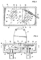
- the transmission assembly T has a housing 50 including a bottom wall 52 and a cover plate 54.
- First valve shaft 28 extends through an opening 56 in bottom wall 52 while second valve shaft 30 extends through an opening 58 in bottom wall 52.
- a drive shaft 62 from actuator A extends through an opening 60 in cover plate 54 of transmission assembly T.
- Drive shaft 62 is fixedly connected to a generally triangular cam plate 64 of a cam assembly C such that cam plate 64 rotates in response to rotation of drive shaft 62.
- Valve shaft 28 is connected to a first link member 66 for rotational movement therewith while valve shaft 30 is connected to a second link member 68 for rotation movement therewith.
- Cam assembly C further includes a first cam follower 70 which has a cylindrical outer surface and is rotatably journaled on cam plate 64.
- Cam assembly C also has a second cam follower 72 which has an outer cylindrical surface and which is rotatably journaled on cam plate 64, first and second cam followers 70 and 72 being spaced, as shown, from one another on cam plate 64.
- Link members 66 and 68 can generally be considered geneva links and, as shown, have a generally U-shape, first link 66 having a first slot 74, second link member 68 having a second slot 76.
- Slot 74 has a first portion adjacent the mouth of slot 74 defined by first and second, opposed, arcuate surfaces 78 and 80.
- Contiguous arcuate side surface 78 and further defining slot 74 is a substantially straight side surface 82 while contiguous arcuate side surface 80 is a substantially straight side surface 84, side surfaces 82 and 84 being substantially parallel to one another.
- second slot 76 is defined by opposed, arcuate side surfaces 86 and 88, arcuate side surface 86 being contiguous a substantially straight side surface 90, arcuate surface 88 being contiguous a substantially straight side surface 90, side surfaces 90 and 92 being substantially parallel to one another.
- Arcuate surfaces 78, 80, 86 and 88 all form circular arcs. In the position shown in Figs. 3 and 5, the radius of curvature of surfaces 86 and 80 are concentric with the radius of curvature around the fixed axis 62 defined by shaft about which cam plate 64 rotates.
- Parallel side surface 82 forms a first cam surface on link member 66 while parallel side surface 84 forms a second cam surface on link member 66.
- Parallel side surface 92 forms a third cam surface on link member 68 while parallel side surface 90 forms a fourth cam surface on link member 68.
- bowden cable 46 Also attached to cam plate 64 is bowden cable 46, bowden cable 46 being slidably mounted in brackets 100 and 102 secured to cover plate 54 and is pivotally connected to cam plate 64 by means of pivot connection 104.
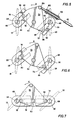
- Fig. 5 which shows the position of the cam plate 64 rotated approximately 15° from the position shown in Fig. 3, it can be seen that the valves 14 and 16 and hence disks 18 and 20 are still in the fully closed position.
- the cam followers 70 and 72 have moved in a lost motion path along the surfaces 80 and 86 respectively, as cam plate 64 has rotated from the position shown in Fig. 3 to the position shown in Fig. 5. Accordingly, no movement of link members 66 or 68 has occurred. Any further rotation of shaft 62 by means of actuator A in the direction shown by arrow X will result in rotation of cam plate 64 in the direction shown by arrow X. It can be seen that in the position shown in Fig.
- first cam follower 70 is just at the point of engagement with side surface 82. Accordingly, any further movement of cam plate 64 in the direction of arrow X will cause link 66 to rotate around the axis determined by shaft 28 in a clockwise direction. This is graphically shown in Fig. 6 where cam plate 64 has rotated, cam follower 70 engaging the first cam surface formed by parallel side surface 82. It will be observed that although disk 18 has now moved from the fully closed position to a partially open position in Fig. 6, disk 20 is still in the fully closed position.
- cam follower 72 has been moving on arcuate surface 86 which, since it is a circular arc having a concentric radius of curvature to the radius of curvature around shaft 62 results in lost motion to the extent that no movement of link member 68 occurs.
- cam follower 70 continues to move along surface 82 with resultant further clockwise rotation of link member 66 and hence further opening of valve disk 18.
- cam follower 72 is no longer on the lost motion path defined by arcuate surface 86 but rather has engaged side surface 92 thereby forcing link member 68 to also rotate in a clockwise direction.
- the rotation of link member 68 results in rotation of disk 20 into the partially open position shown in Fig. 7. It will be observed that the lost motion that occurs between cam follower 72 and link member 68 permits valve disk 18 to be cracked open just before valve disk 20 is cracked open. Accordingly, torquing requirements are reduced and actuator sizing can be downgraded since it is not necessary to disengage both disks 18 and 20 from their tight, interference fit with the valve seat at the same time.
- the time differential between when disk 18 opens and disk 20 opens can be varied.
- disk 18 commences opening at time t0
- cam follower 70 has just engaged the first cam surface formed by parallel side surface 82
- disk 20 will open at a time t1 where t0-t1 equals the time between when cam follower 72 engages surface 92 and cam follower 72 traverse the lost motion path and engages the cam surface formed by parallel side surface 92.
- the time differential can likewise be varied.
- Figs. 8 and 9 depict further rotational movement of cam plate 64 in the direction of arrow X and hence further clockwise movement of link members 66 and 68 in response to engagement of cam follower 70 with surface 82 and cam follower 72 with surface 92.
- valve disks 18 and 20 are shown in the fully opened position. It will thus be seen that as cam plate 64 rotates between the position shown in Fig. 5 and the position shown in Fig. 9, cam follower 70 engages a cam surface defined by parallel side surface 82 whereas cam follower 72 engages a cam surface defined by parallel side surface 92. Thus, cam follower 72 first moves along a lost motion path defined by arcuate surface 86 prior to engaging the cam surface defined by parallel side surface 92.
- arcuate surface 78 has a radius of curvature equal to a radius of curvature around the axis determined by shaft 62. It will thus be appreciated that as the valves 14, 16 move to the closed position as shown in Fig. 5, disk 20 will be in the fully closed position first followed by the closing of valve disk 18.
- bleed valve 38 would normally be in the opened position.
- the movement of cam plate 64 about 15°, i.e. to the position shown in Fig. 5, will cause bleed valve 38 to be moved from the fully opened to the fully closed position as cam plate 64 moves from the position shown in Fig. 3 to the position shown in Fig. 5.
- the block valves 14, 16 will be sequenced to open and close one after the other and at the same time bleed valve 38 will be sequenced to move from the opened to the closed position all by virtue of the rotation of cam plate 64.
- the cam assembly C1 includes a cam plate 110 affixed to and rotatable with drive shaft 62, drive shaft 62 defining a fixed axis about which cam plate 110 rotates.
- the cam assembly C1 further includes a first cam follower 114 rotatably journaled on cam plate 110 and a second cam follower 116 spaced from cam follower 114 and also rotatably journaled on cam plate 110.
- cam followers 114 and 116 have cylindrical outer surfaces.
- First link member 118 is attached to the shaft 120 of a valve (not shown) and having a valve disk 122 so as to be rotatable with shaft 120.
- Second link member 124 is likewise affixed to a shaft 126 of a second block valve (not shown) provided with a valve disk 128 whereby rotation of link member 124 results in rotation of shaft 126 and hence opening and closing of valve disk 128.
- Link member 118 has a slot 130 having a first portion adjacent to the mouth defined by an arcuate side surface 132 and an opposed, chamfered side surface 134 and a second, contiguous portion defined by first parallel side surface 136 and a second parallel side surface 138.
- Link 124 has a slot 140 having a first portion adjacent to the mouth of slot 140 defined by an arcuate side surface 142 and an opposed, chamfered side surface 144 and a second, contiguous portion defined by a first parallel side surface 146 and a second parallel side surface 148.
- arcuate surface 142 has a circular radius of curvature which is concentric with a radius of curvature around the fixed axis determined by drive shaft 62.
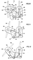
- Fig. 10 depicts the condition in which both of the block valves having valve disks 122 and 128 are in the fully closed position, whereas Fig. 15 shows the valves in the fully open position. It can be seen that as cam plate 110 rotates counterclockwise in the direction shown by arrow Y, link members 118 and 124 will be caused to rotate in a clockwise direction.
- cam follower 114 is at the juncture between the first portion and the second portion of slot 130 i.e. at the point where any counterclockwise movement of cam plate 110 will bring cam follower 114 into engagement with parallel side surface 136 and effect movement of link 118.
- no movement of link 124 occurs in this initial period since cam follower 116 is traversing a lost motion path defined by arcuate surface 142. It is not until cam plate 110 has been moved sufficiently (see Fig. 11) that cam follower 116 now comes into engagement with parallel side surface 148, any further movement of cam plate 110 in the counterclockwise direction resulting in movement of link 124 in the clockwise direction.
- valve disk 128 will initially be moved towards the closed position followed by initial movement of valve disk 122 towards the closed position, the time lag being determined by the length of the lost motion path traversed by cam follower 114, as explained above. Likewise, disk 128 will be moved to the fully closed position just ahead of disk 122.
- a double block and bleed system employing a different embodiment of the transmission assembly of the present invention and a modified bleed valve.
- an annular body 148 forms a chamber 150 between first and second block valves 14, 16, respectively.
- a rotatable bleed valve element 154 Disposed in a cavity 152 formed in body 148 is a rotatable bleed valve element 154, valve element 154 serving to provide open communication between chamber 150 and a drain port 156 whereby chamber 150 can be drained of any fluid contained therein.
- the double block and bleed system shown in Fig. 16 could also be provided with a suitable CIP assembly such as shown in Fig. 1 so that the interior of chamber 150 could be thoroughly washed with a cleaning solution.
- Valve element 154 is connected by means of a shaft 158 and meshed bevel gears 160 and 162 to a rotatable shaft 164 whereby any rotation of shaft 164 will be transmitted through gears 160 and 162 to shaft 158 resulting in rotation of bleed valve 154.
- Shaft 164 extends through a bore 166 formed in body 148 which in turn is fitted with a neck 170 having a bore 172 through which shaft 164 extends.
- Neck 170 is also received in a counterbore in the bottom wall 174 of transmission assembly T1, the counterbore being in register with a bore passing through bottom wall 174 to the interior of transmission assembly T1.
- Shaft 164 is connected by a coupling 176 to a shaft 178 which extends through the bore in the bottom wall 174 of transmission assembly T1, the end of shaft 178 projecting into transmission assembly T1 having affixed thereto a bevel gear 180.
- Bevel gear 180 meshes with a second bevel gear 182 which is affixed to a rotatable gear shaft 184 journaled for rotation at right angles to shaft 178 by means of a mounting bracket 186 secured to the bottom wall 174 of transmission assembly T1 and a bore 188 formed in a side wall of the housing 190 forming transmission assembly T1.
- Actuator A is mounted atop transmission assembly T1, drive shaft 62 extending through a bore 194 in cover plate 196 of transmission assembly T1.
- Drive shaft 62 is fixedly secured to cam plate 198 disposed in transmission assembly T1 and forms a fixed axis about which cam plate 198 rotates.
- Valve shaft 28 is attached to link member 200 for rotational movement therewith while valve shaft 30 is attached to a link member 202 for rotation movement therewith.
- the cam assembly C2 further includes a first cam follower 204 which has a cylindrical outer surface and is rotatably journaled in cam plate 198.
- Cam assembly C2 further includes a second cam follower 206 which is rotatably journaled on cam plate 198, cam follower 206 likewise having an outer cyldinrical surface, cam followers 204 and 206 being spaced, as shown from one another on cam plate 198.
- the operative connection between cam plate 198 and links 200 and 202 and the opening and closing of valves 14 and 16 is substantially as described above with respect to Figs. 10-15 and hence will not be described in any detail here.
- crank assembly 210 Disposed in transmission assembly T1 is a crank assembly shown generally as 210, crank assembly 210 being mounted for pivotal movement around pin 212 secured to bottom wall 174, pin 212 forming a fixed axis about which crank assembly 210 rotates.
- crank assembly 210 Secured to gear shaft 184 for rotational movement therewith is an arm 214, arm 214 being pivotally secured to a link 216 which in turn is pivotally secured to an arm portion 218 of crank assembly 210 by means of a pivot connection 220 attached to arm portion 218.
- Crank assembly 210 also includes an arcuate surface 222 defining a lost motion path, surface 222 having a circular radius of curvature which, in the position shown in Fig. 18, is concentric with a radius of curvature around an axis formed by shaft 62 about which cam plate 198 rotates.
- Surface 222 terminates in a recess 224 which is partially formed by a projection 226 forming an engagement surface 228 for a purpose described hereafter.
- Mounted on cam plate 198 of cam assembly C2 is a third cam follower 230 which is rotatably journaled on cam plate 198 and which also has a cylindrical outer surface. In the position shown in Fig. 18 wherein both of the block valves 14, 16 are in the opened position, cam follower 230 is substantially at a terminal position of the lost motion path defined by surface 222.
- cam plate 198 is rotated in a clockwise direction, third cam follower 230 will follow the lost motion, path defined by surface 222 and crank assembly 210 will remain stationary until cam follower 230 reaches a second terminal position along the lost motion path defined by surface 222 at which point cam follower 230 will engage engagement surface 228 formed on projection 226. Further rotation of cam plate 198 in the clockwise direction will now rotate cam assembly 210 in a counterclockwise direction around axis 212. This in turn will result in the movement of link member 216 in the direction shown by arrow W.
- cam follower 230 will move along engagement surface 228 until it is received in recesss 224 at which point block valves 14 and 16 will now be in the fully closed position as shown in Fig. 19.
- cam follower 230 engages engagement surface 228 continued rotational movement of cam plate 198 results in rotational movement of cam assembly 210 and hence linear movement of link member 216 in the direction shown by arrow W which will result in rotational movement of shaft 184 connected to gear 182.
- Gear 182 will in turn rotate gear 180, shaft 178, shaft 164 and ultimately gears 162, 160 which will in turn effect rotation of valve element 154.
- bleed valve 154 will be moved into the fully opened position by the above-described action.
- cam follower 230 will now be forced out of recess 224 and in doing so will rotate crank assembly 210 in a clockwise direction thereby moving bleed valve 154 back into a closed position when crank assembly 210 has been turned to the position shown in Fig. 18. It will be appreciated that in this embodiment as in the previously described embodiments, the block valves will be sequentially moved from their initial closed position. Likewise, when the block valves are moved from the closed to the open positions, block valve 14 will commence initial opening motion prior to initial opening movement of block valve 16.
- Cam plate 300 which is affixed to actuator drive shaft 62 for rotation therewith has affixed thereto a rod member 302, rod member 302 being secured to cam plate 300 by a bracket 304.
- rod member 302 has an end portion 306 which projects beyond the outer periphery of cam plate 300.
- Bevel gear 182 is attached to a gear shaft 308 which is rotatably journaled in a bracket 310 secured to the bottom 312 of transmission assembly T2.
- the gear shaft 308 has a reduced diameter portion 314 which is journaled in the bore 316 in a side wall 318 of transmission assembly T2.
- Attached to a reduced diameter portion 320 of gear shaft 308 for rotation therewith is a U-shaped member 322 having a receiving slot 324. It will be appreciated that if any force is applied to U-shaped member 322 to result in rotation of gear shaft 308, shaft 178 and hence the bleed valve 154 will be caused to rotate in response thereto as described with respect to the embodiment shown in Figs. 18-21.
- the means to operate the bleed valve does not involve a rotatable cam follower attached to cam plate 300 but rather relies on the lost motion between the position of rod member 302 shown in Fig. 22 to the position of rod member 302 when cam plate 300 has rotated to the point where the end 306 of rod member 302 first engages U-shaped member 322 to induce rotation thereof.
- transmission assembly T2 would sequence the opening of the block valves so that they neither opened nor closed simultaneously. Futhermore, the bleed valve would be synchronized so as to be closed when the block valves were in the open position and open when the block valves were in the closed position.
Landscapes
- Engineering & Computer Science (AREA)
- General Engineering & Computer Science (AREA)
- Mechanical Engineering (AREA)
- Mechanically-Actuated Valves (AREA)
Applications Claiming Priority (2)
| Application Number | Priority Date | Filing Date | Title |
|---|---|---|---|
| US07/246,258 US4846225A (en) | 1988-09-19 | 1988-09-19 | Transmission assembly for use with double block and bleed system |
| US246258 | 1988-09-19 |
Publications (1)
| Publication Number | Publication Date |
|---|---|
| EP0364108A1 true EP0364108A1 (de) | 1990-04-18 |
Family
ID=22929931
Family Applications (1)
| Application Number | Title | Priority Date | Filing Date |
|---|---|---|---|
| EP19890309372 Withdrawn EP0364108A1 (de) | 1988-09-19 | 1989-09-14 | Übertragungsgetriebe für ein doppeltes Absperrventil- und Ablasssystem |
Country Status (6)
| Country | Link |
|---|---|
| US (1) | US4846225A (de) |
| EP (1) | EP0364108A1 (de) |
| JP (1) | JPH02146388A (de) |
| KR (1) | KR900005107A (de) |
| AU (1) | AU4138989A (de) |
| BR (1) | BR8904706A (de) |
Cited By (8)
| Publication number | Priority date | Publication date | Assignee | Title |
|---|---|---|---|---|
| DE19713125A1 (de) * | 1997-03-27 | 1998-10-08 | Nord Micro Elektronik Feinmech | Stufenventil, insbesondere Kabinenabluftventil in einem Fluggerät, und Verfahren zur Regulierung des Kabinendrucks |
| US6273136B1 (en) | 1998-03-25 | 2001-08-14 | Nord-Micro Elektronik Feinmechanik | Differential valve, specifically a cabin air discharge valve in an aircraft, and method for regulating cabin pressure |
| CN104948776A (zh) * | 2015-07-15 | 2015-09-30 | 衢州市依科达节能技术有限公司 | 一种双芯离合控制阀门 |
| CN104964045A (zh) * | 2015-07-16 | 2015-10-07 | 衢州市依科达节能技术有限公司 | 一种滑移控制双芯阀门 |
| CN105351537A (zh) * | 2015-11-19 | 2016-02-24 | 成都九十度工业产品设计有限公司 | 一种双阀瓣蝶阀 |
| EP2930407B1 (de) | 2014-04-10 | 2017-01-25 | Linde Aktiengesellschaft | Ventilanordnung |
| EP3680525A1 (de) * | 2019-01-14 | 2020-07-15 | Illinois Tool Works, Inc. | Verstellbares ventil |
| EP3680524A1 (de) * | 2019-01-14 | 2020-07-15 | Illinois Tool Works, Inc. | Betätigungsmechanismus |
Families Citing this family (24)
| Publication number | Priority date | Publication date | Assignee | Title |
|---|---|---|---|---|
| DE3909570A1 (de) * | 1989-03-23 | 1990-09-27 | Vdo Schindling | Lastverstelleinrichtung |
| US5438980A (en) * | 1993-01-12 | 1995-08-08 | Puritan-Bennett Corporation | Inhalation/exhalation respiratory phase detection circuit |
| DE4419545C1 (de) * | 1994-06-03 | 1996-02-22 | Pfannenschmidt Erhard | Vorrichtung zum gemeinsamen Schalten von zwei Armaturen |
| DE19753778B4 (de) * | 1997-12-04 | 2004-02-26 | Robert Bosch Gmbh | Sensor |
| ITTO20031052A1 (it) * | 2003-12-30 | 2005-06-30 | Paolo Debolini | Dispositivo di carico/scarico di apparecchiature di processo. |
| ITBO20040124A1 (it) | 2004-03-01 | 2004-06-01 | Vima Impianti S R L | Dispositivo valvolare |
| ITBO20040362A1 (it) * | 2004-06-08 | 2004-09-08 | Vima Impianti Srl | Apparecchiattura per lavaggio e dispositivo valvolare comprendente tale apparecchiatura |
| US7568503B2 (en) * | 2005-08-10 | 2009-08-04 | Cameron International Corporation | Compressor throttling valve assembly |
| FR2900455B1 (fr) * | 2006-04-26 | 2008-07-04 | Valeo Sys Controle Moteur Sas | Vanne a deux papillons actionnes par un moteur commun |
| DE102008022435A1 (de) * | 2008-05-07 | 2009-11-12 | Karl Dungs Gmbh & Co. Kg | Ventilbaueinheit mit zwei Drehklappenventilen |
| GB201011991D0 (en) * | 2010-07-16 | 2010-09-01 | Chargepoint Technology Ltd | Improvements relating to valves |
| AU2012234908A1 (en) * | 2011-03-28 | 2013-11-14 | Southern Engineering Services Pty Ltd | Fluid flow control assembly |
| CN102155558A (zh) * | 2011-04-15 | 2011-08-17 | 浙江特技阀门有限公司 | 离合联动双截止迷宫式泄放阀 |
| GB2493152A (en) * | 2011-07-25 | 2013-01-30 | Aes Eng Ltd | Modular valve with block and bleed functions |
| CN103090040A (zh) * | 2011-10-31 | 2013-05-08 | 朱万枫 | 智能球阀 |
| FR2984960B1 (fr) * | 2011-12-21 | 2013-12-20 | Valeo Sys Controle Moteur Sas | Doseur deux voies avec dosage sur chaque voie |
| FR3004504B1 (fr) * | 2013-04-12 | 2015-04-24 | Valeo Sys Controle Moteur Sas | Vanne, notamment de controle moteur, dotee d’un volet de dosage et d’un volet d’aiguillage |
| US10450815B2 (en) | 2016-11-21 | 2019-10-22 | Cameron International Corporation | Flow restrictor system |
| CN109340404B (zh) * | 2018-11-01 | 2023-07-28 | 福建菲达阀门科技股份有限公司 | 一种大口径气动多通偏心蝶阀 |
| CN111434959B (zh) * | 2019-01-14 | 2025-06-27 | 伊利诺斯工具制品有限公司 | 驱动机构 |
| DE102021116913A1 (de) * | 2020-10-19 | 2022-04-21 | ECO Holding 1 GmbH | Ventilsteuervorrichtung für einen Kühlmittelkreislauf eines Kraftfahrzeugs |
| CN113175534A (zh) * | 2021-04-21 | 2021-07-27 | 星五季(江苏)科技发展有限公司 | 一种防冻效果好的双法兰蝶阀 |
| CN114655579B (zh) * | 2022-03-14 | 2023-08-01 | 上海吉啸电子科技有限公司 | 一种用于cds原液桶的氮封装置 |
| US20250020230A1 (en) * | 2023-07-10 | 2025-01-16 | Illinois Tool Works Inc. | Rotating Valve System |
Citations (4)
| Publication number | Priority date | Publication date | Assignee | Title |
|---|---|---|---|---|
| FR1440777A (fr) * | 1965-04-21 | 1966-06-03 | Jouvenel & Cordier | Dispositif de commande réglable, notamment pour trains de robinets ou de distributeurs à débattement angulaire |
| DE1298805B (de) * | 1965-07-20 | 1969-09-18 | Getting Jonas Titan Sa | Vorrichtung zur intermittierenden Steuerung der OEffnung und/oder Schliessung von wenigstens zwei Haehnen |
| GB2064730A (en) * | 1979-12-01 | 1981-06-17 | Schleicher Leonhard | Improvements in pipe line shut-off valves with a leakage safety device |
| EP0034313A1 (de) * | 1980-02-13 | 1981-08-26 | COMPAGNIE INDUSTRIELLE DES TELECOMMUNICATIONS CIT-ALCATEL S.A. dite: | Dreiwegeventil |
Family Cites Families (2)
| Publication number | Priority date | Publication date | Assignee | Title |
|---|---|---|---|---|
| US3007489A (en) * | 1959-08-17 | 1961-11-07 | Nat Valve And Mfg Company | Multiple valve assembly |
| US3528447A (en) * | 1969-02-10 | 1970-09-15 | Acf Ind Inc | Tandem ball valve assembly with purging and leak sensing means |
-
1988
- 1988-09-19 US US07/246,258 patent/US4846225A/en not_active Expired - Fee Related
-
1989
- 1989-09-14 AU AU41389/89A patent/AU4138989A/en not_active Abandoned
- 1989-09-14 EP EP19890309372 patent/EP0364108A1/de not_active Withdrawn
- 1989-09-18 JP JP1240272A patent/JPH02146388A/ja active Pending
- 1989-09-19 KR KR1019890013524A patent/KR900005107A/ko not_active Withdrawn
- 1989-09-19 BR BR8904706A patent/BR8904706A/pt unknown
Patent Citations (4)
| Publication number | Priority date | Publication date | Assignee | Title |
|---|---|---|---|---|
| FR1440777A (fr) * | 1965-04-21 | 1966-06-03 | Jouvenel & Cordier | Dispositif de commande réglable, notamment pour trains de robinets ou de distributeurs à débattement angulaire |
| DE1298805B (de) * | 1965-07-20 | 1969-09-18 | Getting Jonas Titan Sa | Vorrichtung zur intermittierenden Steuerung der OEffnung und/oder Schliessung von wenigstens zwei Haehnen |
| GB2064730A (en) * | 1979-12-01 | 1981-06-17 | Schleicher Leonhard | Improvements in pipe line shut-off valves with a leakage safety device |
| EP0034313A1 (de) * | 1980-02-13 | 1981-08-26 | COMPAGNIE INDUSTRIELLE DES TELECOMMUNICATIONS CIT-ALCATEL S.A. dite: | Dreiwegeventil |
Cited By (12)
| Publication number | Priority date | Publication date | Assignee | Title |
|---|---|---|---|---|
| DE19713125A1 (de) * | 1997-03-27 | 1998-10-08 | Nord Micro Elektronik Feinmech | Stufenventil, insbesondere Kabinenabluftventil in einem Fluggerät, und Verfahren zur Regulierung des Kabinendrucks |
| DE19713125C2 (de) * | 1997-03-27 | 1999-03-25 | Nord Micro Elektronik Feinmech | Verfahren zur Regulierung des Kabinendrucks in einem Fluggerät und Stufenventil hierfür |
| US6273136B1 (en) | 1998-03-25 | 2001-08-14 | Nord-Micro Elektronik Feinmechanik | Differential valve, specifically a cabin air discharge valve in an aircraft, and method for regulating cabin pressure |
| EP2930407B1 (de) | 2014-04-10 | 2017-01-25 | Linde Aktiengesellschaft | Ventilanordnung |
| CN104948776A (zh) * | 2015-07-15 | 2015-09-30 | 衢州市依科达节能技术有限公司 | 一种双芯离合控制阀门 |
| CN104964045A (zh) * | 2015-07-16 | 2015-10-07 | 衢州市依科达节能技术有限公司 | 一种滑移控制双芯阀门 |
| CN104964045B (zh) * | 2015-07-16 | 2017-04-05 | 衢州市依科达节能技术有限公司 | 一种滑移控制双芯阀门 |
| CN105351537A (zh) * | 2015-11-19 | 2016-02-24 | 成都九十度工业产品设计有限公司 | 一种双阀瓣蝶阀 |
| EP3680525A1 (de) * | 2019-01-14 | 2020-07-15 | Illinois Tool Works, Inc. | Verstellbares ventil |
| EP3680524A1 (de) * | 2019-01-14 | 2020-07-15 | Illinois Tool Works, Inc. | Betätigungsmechanismus |
| US11085547B2 (en) | 2019-01-14 | 2021-08-10 | Illinois Tool Works Inc. | Adjustable valve |
| US11236836B2 (en) | 2019-01-14 | 2022-02-01 | Illinois Tool Works Inc. | Actuating mechanism for actuating valves |
Also Published As
| Publication number | Publication date |
|---|---|
| BR8904706A (pt) | 1990-05-01 |
| JPH02146388A (ja) | 1990-06-05 |
| KR900005107A (ko) | 1990-04-13 |
| US4846225A (en) | 1989-07-11 |
| AU4138989A (en) | 1990-03-22 |
Similar Documents
| Publication | Publication Date | Title |
|---|---|---|
| US4846225A (en) | Transmission assembly for use with double block and bleed system | |
| US6378841B1 (en) | Quarter-turn rotary plug valve with seats reciprocable during operation | |
| RU2121102C1 (ru) | Соединение с двумя шаровыми затворами, обеспечивающее экстренное разъединение, исключающее утечку | |
| US3877677A (en) | Valve operator for butterfly valves or the like | |
| US5009388A (en) | Magnetic-controlled valve for fluid pipelines | |
| CA2085658A1 (en) | Dispensing taps | |
| US6328051B1 (en) | Dual pendulum valve assembly | |
| IL165307A (en) | Shut-off fitting | |
| JPH04228980A (ja) | 管を連結するため回転弁を合体する装置 | |
| JP3734276B2 (ja) | 複合ちょう形弁装置 | |
| AU2019276373A1 (en) | A ball valve and valve operating method | |
| CN107740868B (zh) | 一种带有预泄压功能的蝶阀 | |
| AU649895B2 (en) | Actuator for a rotary valve | |
| US4073470A (en) | Press disc valve | |
| JP2004507416A (ja) | 2つの保管手段および/または搬送手段を固定保持装置によって連結する装置 | |
| RU189234U1 (ru) | Неполноповоротный двухскоростной привод для трубопроводной арматуры | |
| KR101736392B1 (ko) | 블라인드 밸브형 게이트 밸브 | |
| EP0998642B1 (de) | Drehender ventilaktor mit hohem-niedrigem-hohem drehmoment | |
| CN2347027Y (zh) | 多阀控制装置 | |
| CN114413019A (zh) | 超高压dbb功能双联球阀 | |
| US5165657A (en) | Actuator for a rotary valve | |
| JP2003148639A (ja) | 三方切替弁ユニット | |
| CN1900570A (zh) | 二路四通联动水阀 | |
| KR19990064254A (ko) | 밸브 | |
| CN216479033U (zh) | 一种多功能电动球阀 |
Legal Events
| Date | Code | Title | Description |
|---|---|---|---|
| PUAI | Public reference made under article 153(3) epc to a published international application that has entered the european phase |
Free format text: ORIGINAL CODE: 0009012 |
|
| AK | Designated contracting states |
Kind code of ref document: A1 Designated state(s): DE FR GB IT NL |
|
| 17P | Request for examination filed |
Effective date: 19900320 |
|
| 17Q | First examination report despatched |
Effective date: 19910709 |
|
| STAA | Information on the status of an ep patent application or granted ep patent |
Free format text: STATUS: THE APPLICATION IS DEEMED TO BE WITHDRAWN |
|
| 18D | Application deemed to be withdrawn |
Effective date: 19920120 |