EP0364154B1 - Appareil de mesures optiques destiné à l'examen oculaire - Google Patents
Appareil de mesures optiques destiné à l'examen oculaire Download PDFInfo
- Publication number
- EP0364154B1 EP0364154B1 EP89310181A EP89310181A EP0364154B1 EP 0364154 B1 EP0364154 B1 EP 0364154B1 EP 89310181 A EP89310181 A EP 89310181A EP 89310181 A EP89310181 A EP 89310181A EP 0364154 B1 EP0364154 B1 EP 0364154B1
- Authority
- EP
- European Patent Office
- Prior art keywords
- axis
- eye
- aligning
- light receiving
- optical
- Prior art date
- Legal status (The legal status is an assumption and is not a legal conclusion. Google has not performed a legal analysis and makes no representation as to the accuracy of the status listed.)
- Expired - Lifetime
Links
- 230000003287 optical effect Effects 0.000 title claims description 222
- 210000004087 cornea Anatomy 0.000 claims description 35
- 238000010276 construction Methods 0.000 description 6
- 238000012544 monitoring process Methods 0.000 description 5
- 210000001525 retina Anatomy 0.000 description 5
- 238000010586 diagram Methods 0.000 description 4
- 210000000887 face Anatomy 0.000 description 1
- 239000011521 glass Substances 0.000 description 1
- 239000011159 matrix material Substances 0.000 description 1
- 238000000034 method Methods 0.000 description 1
Images




Classifications
-
- A—HUMAN NECESSITIES
- A61—MEDICAL OR VETERINARY SCIENCE; HYGIENE
- A61B—DIAGNOSIS; SURGERY; IDENTIFICATION
- A61B3/00—Apparatus for testing the eyes; Instruments for examining the eyes
- A61B3/10—Objective types, i.e. instruments for examining the eyes independent of the patients' perceptions or reactions
- A61B3/14—Arrangements specially adapted for eye photography
- A61B3/15—Arrangements specially adapted for eye photography with means for aligning, spacing or blocking spurious reflection ; with means for relaxing
- A61B3/152—Arrangements specially adapted for eye photography with means for aligning, spacing or blocking spurious reflection ; with means for relaxing for aligning
-
- A—HUMAN NECESSITIES
- A61—MEDICAL OR VETERINARY SCIENCE; HYGIENE
- A61B—DIAGNOSIS; SURGERY; IDENTIFICATION
- A61B3/00—Apparatus for testing the eyes; Instruments for examining the eyes
- A61B3/10—Objective types, i.e. instruments for examining the eyes independent of the patients' perceptions or reactions
Definitions
- the present invention relates to an optical measuring apparatus for measuring an eye, and more particularly, to an optical measuring apparatus for automatically measuring various optical characteristic such as the refractive power of the eye, the curvature of the cornea or the like.
- An automatic refractometer apparatus for automatically measuring the refractive power of an eye
- an automatic keratometer apparatus for automatically measuring the curvature of a cornea
- a measuring optical system is constructed by having the eye disposed at a predetermined position of the optical axis thereof.
- the disposition of the eye requires the following two conditions:
- the optical axis of the apparatus is aligned by the optical axis of the eye, i.e., optical axes-aligned condition is obtained and the focal point of the optical system of a monitoring camera provided in the apparatus coincides with the eye disposed on the measuring optical system of the apparatus, i.e., an in-focus condition is obtained.
- the automatic refractometer observes, through the optical system, an optical target (measuring light) whose image is formed on the eyeground of the eye, namely, on the retina, thus automatically measuring the refractive power of the eye.
- the positions of the measuring optical system of the apparatus and the eye are adjusted to a measurable condition, namely, a condition in which optical axes of the optical system and the eye align with each other and the measuring lights projected by the light projecting optical system are focused on the eye.
- a measurable condition namely, a condition in which optical axes of the optical system and the eye align with each other and the measuring lights projected by the light projecting optical system are focused on the eye.
- the apparatus is moved lengthwise and widthwise so that the position of an axes-aligning mark (reticle pattern) and the position of the image of a light reflected by the cornea displayed on the monitor screen align with each other.
- an optical axes alignment is accomplished.
- the distance between the apparatus and the eye is adjusted.
- the focal point of the optical system of the monitoring camera of the apparatus coincides with the position of the eye disposed on the measuring optical system thereof.
- JP-A-63-65842 discloses an optical measuring instrument for examining an eye, being a non-contact type tonometer.
- the tonometer of JP-A-63-65842 light beams from two sources positioned symmetrically on opposite sides of an optical axis are reflected from the eye to a light receiving sensor. The position of the beams detected by that sensor are then analyzed to determine whether the optical system is in focus.
- this document corresponds to the pre-characterising part of claim 1.
- the present invention seeks to provide an optical measuring apparatus for examining an eye provided with a mechanism capable of reliably obtaining axes-aligned and in-focus conditions in an appropriate timing. According to the present invention, there is provided an optical measuring apparatus for examining an eye having:
- the optical axes aligning beams reflected by the cornea is not received by the light receiving sensor. Even if the beams are received by the light receiving sensor, the level of the signals indicating the cornea-reflected images is lower than the reference value. This condition is detected by the first comparing means. Thus, an in-focus state can be obtained. Further, when the axes-aligning error is relatively large, the cornea-reflected images are not received by the light receiving sensor. This state is also discriminated by the first comparing means.
- the mis-alignments in X-direction and Y-direction in the light receiving sensor are considered.
- the mis-alignment in X-direction is detected by the discriminating means and the mis-alignment in Y-direction is detected by the calculating means and the second comparing means.
- an optical axes-alignment is accurately accomplished.
- the second comparing means outputs to the apparatus a signal indicating that the projection of a measuring light be started.
- the axes-aligning-focusing system has a pair of optical axes-aligning light source means for projecting a pair of beams close to each other and arranged in X-direction on the eye.
- the pair of optical axes-aligning light source means is disposed to be symmetrical with respect to the optical axis in X-direction.
- the optical axes-aligning-focusing means includes a first discriminating means for discriminating whether or not cornea-reflected images are formed on the light receiving sensor on the X-axis thereof; a second discriminating means for discriminating whether or not cornea-reflected images, formed on the light receiving sensor on the X-axis thereof and detected by the first discriminating means, do not overlap with each other and separated from each other; and a calculating means for calculating the distances between the Y-axis of the light receiving sensor and each of two images disposed on both outer sides among four images received by the light receiving sensor on the X-axis thereof; and comparing means for comparing two distances calculated by the calculating means with each other and outputting a signal indicating the start of the projection of the measuring light if the difference between the two calculated distances is in the tolerance.
- an optical axes alignment in Y-direction of the light receiving sensor is carried out by the first discriminating means and a focusing adjustment is performed by the second discriminating means. That is, the first discriminating means detects whether or not a cornea-reflected image is formed on the X-direction of the light receiving sensor. Thus, an optical axes alignment in Y-direction in the light receiving sensor is effected.
- the second discriminating means detects whether or not four images reflected by the cornea do not overlap with each other or are separated on the light receiving sensor, thus discriminating whether or not the lights emitted by the optical axes-aligning-focusing means is focused on the eye.
- the calculating means and the comparing means detect whether or not the four images, namely, a pair of cornea-reflected images received by the X-axis on the left and right sides thereof are symmetrical with respect to the Y-axis thereof. That is, the calculating means and the comparing means detects an optical axes-aligned state. When the optical axes-aligned state is obtained, the comparing circuit outputs to the apparatus a signal indicating that the projection of a measuring light be started.
- FIG. 1 is an illustration showing the entire optical system of an automatic refractometer of an optical measuring apparatus for examining an eye (hereinafter referred to as apparatus) in accordance with a first embodiment of the present invention.
- Fig. 2 shows a measuring light projecting optical system shown in Fig. 1.
- Fig. 3 shows a light receiving optical system shown in Fig. 1.
- Fig. 4 shows an optical axes-aligning-focusing optical system shown in Fig. 1.
- the optical axis (A) of the measuring light projecting optical system extends from a light source 2 to a first half mirror 3 and is reflected by a first half mirror 3 at an angle of 90°, then travels to an eye to be examined (hereinafter referred to as eye E).
- An infrared ray emitting diode is used as the light source 2.
- Various optical elements are disposed along an optical axis a1 extending rectilinearly from the light source 2 to the first half mirror 3.
- a measuring light emitted by the light source 2 is reflected by the first half mirror 3, thus traveling from the apparatus to the eye E along an optical axis a2.
- the measuring light can be projected into the eye E by disposing the optical axis a E of the eye E on the optical axis a2.
- the following optical elements are disposed along the optical axis a1 between the light source 2 and the first half mirror 3 in the following order: a collimator lens 4, a quadrangular pyramid prism 5, a diaphragm 6, a light projecting lens 7, a four-opening mirror 8, and an eyepiece 9.
- the quadrangular pyramid prism 5 disperses an infrared ray which has been emitted by the light source 2 and passed through the collimator lens 4 into four beams concentrically spaced from each other at an an angular interval of 90° in the periphery of the optical axis a1.
- the diaphragm 6 is disposed at the focal point of the light projecting relay lens 7. Therefore, the four beams which have been dispersed by the quadrangular pyramid prism 5 pass through the diaphragm 6, and thereafter, are incident on the light projecting relay lens 7. Then, the four beams become parallel with the optical axis a1, thus forming four spot patterns.
- the four-opening mirror 8 reflects the measuring light reflected by the retina of the eye E at an angle of 90°, the upper face of which forms 45° with the optical axis a1.
- the light projecting optical system 1 four small openings are formed on the four-opening mirror 8 at the portions corresponding to the light paths of the four spot patterns so that the four-opening mirror 8 does not intercept the optical path of the four spot patterns.
- the measuring lights which have passed through the openings of the four opening mirror 8 are incident on the eyepiece 9 as four spot patterns. Then, the measuring lights are reflected at an angle of 90°, thus entering into the eye E.
- optical axes b1 and b2 disposed from the eye E to the four-opening mirror 8 and forming part of optical axis (B) of the light receiving system 10 coincide with the optical axes a2 and a1 of the optical axis (A) of the light projecting system 1, respectively.
- the measuring lights reflected by the retina travel backward to the four-opening mirror 8 along the optical axes b1 and b2, thus being reflected by the four-opening mirror 8 at an angle of 90°.
- a micromirror 11 having a face parallel with the faces of the four-opening mirror 8 is disposed on the optical axis b3 of the reflected measuring lights.
- the micromirror 11 reflects the reflected measuring lights downward at right angles with the optical axis b3.
- the optical axis b4 pass through the center of the light receiving sensor 13.
- the center of the field is disposed on the optical axis (B) of the light receiving optical system 10.
- the optical axis (B) or b4 passes through the intersection of the X- axis and Y-axis on the light receiving sensor 13.
- a pair of an optical axes-aligning light sources 21, 21 comprising infrared ray emitting diode is horizontal and symmetrical with respect to the optical axis a2.
- the direction of a straight line formed by connecting both the optical axes-aligning light sources 21 and 21 coincides with the direction in which the field is scanned on the light receiving sensor 13.
- a scanning line moves downward sequentially while the field is scanned widthwise in the monitor screen.
- the image in the field is scanned widthwise, i.e., the scanning direction is from left to right as viewed from an operator.
- the diameter of lights emitted by the optical axes-aligning light source 21 are greatly reduced into light beams by the collimator lens 22 disposed forward of the optical axes-aligning light source 21.
- the beams reflected by the cornea travels back in parallel with the optical axis a2.
- the beams are detected by the light receiving sensor 13.
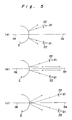
- Figs. 5(a), 5(b), and 5(c) show directions, of lights reflected by the cornea, which differ from each other depending on the distance between the eye E and the optical axes-aligning light source 21.
- Fig. 5(a) shows the case in which the distance therebetween is too short.
- Fig. 5(b) shows the case in which the distance therebetween is appropriate enough to be examined.
- Fig. 5(c) shows the case in which the distance therebetween is too long.
- each of the diameters of the beams emitted by the respective optical axes-aligning light sources is very small and each of the areas of spots of the beams is very small on the cornea.
- each of the diameters of beams reflected by the cornea is small and as such, does not diffuse.
- the optical axes-aligning light source 21 is too far from or near to the eye E, the distance between the optical axis a2 and the beams reflected by the cornea becomes great as the beams travel forward from the eye E.
- the beams reflected by the cornea travel substantially parallel with the optical axis a2, thus reaching the light receiving sensor 13.
- the focal point of the optical system of a monitoring camera coincides with the cornea when the distance between the optical axes-aligning light source 21 and the eye E is as shown in Fig. 5(b).
- the reflected lights from the cornea can be received by the light receiving sensor 13.
- optical axes-aligning beam The optical elements constituting the optical path of beams emitted by the optical axes-aligning light source 21 and reflected by the cornea (hereinafter referred to as optical axes-aligning beam) are described hereinafter.
- An optical axes aligning beam partially pass through the first half mirror 3 is reflected downward at an angle of 90° by a second half mirror 14, then passes through a monitor relay lens 16.
- a first 45° mirror 17 is disposed below the monitor relay lens 16.
- the beam which has passed through the mirror 17 is incident on a reticle plate 18 made of a transparent glass on which a reticle pattern is drawn.
- the reticle plate 18 is conjugate with the eye E with respect to the monitor relay lens 16.
- the beam which has passed through the reticle plate 18 is incident on a second 45° mirror 19 which reflects the beam downward at an angle of 90°.
- the light receiving optical system 10 and the optical axes-aligning-focusing optical system 15 have in common the optical axis b4 disposed below the second 45° mirror 19 and including the image forming lens 12 and the light receiving sensor 13. Accordingly, the optical axes aligning-focusing-optical system 15 has a construction in which the monitoring reticle optical system is incorporated in the optical system of the monitoring camera.
- the micromirror 11 of the optical axes aligning-focusing-optical system 15 is so small that the optical axes aligning beams travel in the periphery thereof.
- the micromirror 11 causes no problem in measuring the refractive power of the eye E.
- a target 20 is disposed on the extension of the optical axis a2 of the light projecting optical system 1 so that a patient watches a far point in having the refractive power of the patient's eye E examined.
- Fig. 6 is a block diagram of the automatic refractometer.
- the measuring beams (emitted by the light source 2) reflected by the retina and beams (emitted by the optical axes-aligning light source 21) reflected by the cornea are received by the light receiving sensor 13 to be scanned, thus sequentially converting the beams into image signals (electric signals). Together with synchronizing signals of the scanning, the image signals are inputted to a comparator 31, a synchronizing signal separator circuit 32, an image processing device 52, and a monitor 53.
- the image signals inputted to the comparator 31 are outputted to an AND circuit 33 in two different levels. That is, one level is higher and the other level is lower than a reference value set in the comparator 31.
- the reference value substantially corresponds to the luminance of the optical axes-aligning light source 21. That is, the level of the signal corresponding to the image of the measuring beam reflected by the retina is lower than the reference value and the signal corresponding to the image of the optical axes-aligning beam reflected by the cornea is lower than the reference value.
- the synchronizing signal inputted to the synchronizing signal separator circuit 32 is separated into a horizontal synchronizing signal and a vertical synchronizing signal.
- the horizontal synchronizing signal is inputted to an X-axis reference generating circuit 34 and a Y-axis reference generating circuit 35.
- the vertical synchronizing signal is inputted to only the X-axis reference generating circuit 34.
- the Y-axis reference generating circuit 35 includes a clock pulse generating circuit and a pulse counter.
- the Y-axis reference generating circuit 35 outputs a timing signal to the AND circuit 41 and a counter 38 for detecting the distance of the right side-spot with respect to Y-axis when the number of pulses counted from the point the horizontal synchronizing signal coincides with Y-axis which passes through the center of the optical axis.
- the AND circuit 33 outputs signals to a right side-spot detecting circuit 36, a left side-spot detecting circuit 37, and a counter 39 for detecting the distance of the left side-spot with respect to Y-axis only when the signal outputted from the comparator 31 is disposed on X-axis, namely, the reference axis.
- the signal corresponding to the beam emitted by the optical axes-aligning light source 21 disposed on the right side is outputted from the right side-spot detecting circuit 36.
- the signal corresponding to the beam emitted by the optical axes-aligning light source 21 disposed on the left side is outputted from the left side-spot detecting circuit 37. That is, the left side-spot detecting circuit 37 comprising a one-pulse counter outputs a signal to the AND circuit 41 when one pulse signal is inputted thereto from the AND circuit 33.
- the right side-spot detecting circuit 36 comprising a two-pulse counter outputs a signal to the counter 38 when two pulse signals are inputted thereto from the AND circuit 33.
- the counters 38 and 39 serve as means for measuring the distance between Y-axis and the right side-spot image of the beam reflected by the cornea and the distance between Y-axis and the left side-spot image of the beam reflected by the cornea.
- the counter 39 starts a counting in response to a signal outputted from the AND circuit 33 and terminates the counting in response to a signal outputted from the AND circuit 41.
- the AND circuit 41 outputs to the counter 39 a stop signal indicating that the counting be stopped.
- the counter 39 terminates the counting.
- the counter 39 outputs to a comparator 40 a counted value corresponding to the distance between Y-axis and the left side-spot image reflected by the cornea.
- the counter 38 starts a counting in response to a signal outputted from the Y-axis reference generating circuit 35 and terminates the counting in response to a signal outputted from the detecting circuit 36.
- the counter 39 outputs to the comparator 40 a counted value corresponding to the distance between Y-axis and the right side-spot image reflected by the cornea.
- the comparator 40 decides whether or not the absolute values counted by the counters 38 and 39 are close to each other and within the tolerance, namely, whether or not the positions of the left side-spot image and right side-spot image of the beams reflected by the cornea are symmetrical with respect to Y-axis. If the counted values are within the tolerance, a signal indicating that a measuring be started is outputted to a microcomputer 51, so that the microcomputer 51 outputs to the light projecting optical system 1 a signal which indicates that a measuring light be projected.
- Figs. 7, 8, and 9 show the following three conditions when an optical axes-alignment and a focusing are carried out.
- Figs. 7(a), 8(a), and 9(a) show images of spots and the eye E displayed on the monitor 53 .
- Figs. 7(b), 8(b), and 9(b) show image signals detected by the light receiving sensor 13 on the X-axis thereof.
- Figs. 7(c), 8(c), and 9(c) show the binary signals of the image signals.
- Fig. 7 shows the condition in which the optical axes of the eye E and the axes-aligning-focusing optical system 15 are aligned with each other and the beams emitted by the axes-aligning-focusing optical system are focused on the eye E.
- Fig. 8 shows the condition in which the beams emitted by the axes-aligning-focusing optical system are focused on the eye E, but optical axes of the eye E and the axes-aligning-focusing optical system 15 are not aligned with each other.
- Fig. 9 shows the condition in which the optical axes of the eye E and the axes-aligning-focusing optical system 15 are aligned with each other, but the beams emitted by the axes-aligning-focusing optical system are not focused on the eye E.
- the optical axes of the eye E and the axes-aligning-focusing optical system 15 are aligned with each other and the beams emitted by the axes-aligning-focusing optical system are focused on the eye E, the images of the eye E and the spot images of the optical axes-aligning beams are clearly displayed on the center of the monitor.
- the spot images P1 and P2 formed by the optical axes-aligning beams are clearly displayed on the monitor screen. That is, as shown in Fig. 7(b), the signal outputted from the light receiving sensor 13 and corresponding to the spot images P1 and P2 has clear peaks PL1 and PL2 at the portions corresponding to the spot images P1 and P2.
- the axes-aligning beams reflected by the cornea can be received by the light receiving sensor 13 and pulse signals PS 1,2 may be outputted from the comparator 31.
- the spot images are not disposed on the X-axis so that no high level signal is outputted. Therefore, it is understood that the optical axes of the eye E and the axes-aligning-focusing system are not precisely aligned with each other.
- the distances of the left side-spot and right side-spot with respect to the Y-axis are compared with each other by the comparator 40.
- the beams emitted by the axes-aligning-focusing optical system are focused on the eye E, but optical axes of the eye E and the axes-aligning-focusing optical system 15 are not aligned with each other, with exception of the case where the axes-aligning error is extremely small, the images of the eye E are clearly displayed on the monitor, while the spots of the optical axes-aligning beams are not displayed on the monitor. Therefore, the signal, corresponding to the spot images, detected by the light receiving sensor 13 on X-axis thereof is almost flat or does not have a peak having a significant peak as exceeding the reference value TL set in the comparator 31 as shown in Fig. 8(b) and the high level and low level signals produced in the comparator 31 have no pulse signals as shown in Fig. 8(c).
- the optical axes of the eye E and the optical axes-aligning-focusing system 15 are aligned with each other, but the beams emitted by the axes-aligning-focusing optical system are not focused on the eye E, the image of the eye E is displayed in the center of the monitor screen, but blurred and the spot images are not displayed on the monitor screen.
- the optical axes-aligning beam reflected by the cornea does not reach the light receiving sensor 13 as described previously referring to Fig. 5. Accordingly, the signal detected by the light receiving sensor 13 on X-axis thereof is low in its level and has hardly any peaks as shown in Fig. 9(b).
- the high level and low level signals produced in the comparator 31 have no pulse signals as shown in Fig. 9(c).
- the focusing error is extremely small so that the axes-aligning beams reflected by the cornea of the eye E can be received by the light receiving sensor 13, the corresponding image signals are outputted from the sensor 13 to the comparator 31.
- the level of the signals are lower than the reference value TL so that no high level signal is outputted from the comparator 31.
- the automatic refractometer provided with the mechanism, for aligning the optical axes of the eye E and the optical axes-aligning-focusing system with each other, which is constructed and operates as above, watching the image displayed on the monitor screen, an operator adjusts the distance between the eye E and the apparatus by moving the main body of the apparatus lengthwise and widthwise so as to alter the condition shown in Fig. 8 or Fig. 9 to the condition shown in Fig. 7.
- the automatic refractometer is capable of measuring the refractive power of the eye E in an appropriate measuring timing.
- Fig. 10 shows the entire optical system of an automatic refractometer. Since the fundamental construction of this optical system is identical to that of the first embodiment, like parts are designated by like reference numerals and the detailed descriptions thereof are omitted.
- a light source means for aligning optical axis of the eye E and that of the optical axes-aligning system in accordance with the second embodiment differs from that of the first embodiment. The light source means is described hereinbelow.
- the light source means comprises an optical axes-align light source 21′, a collimator lens 22′, and a trapezoidal prism 23′.
- a pair of light source means are disposed to be symmetrical with respect to an optical axis a2 similarly to the first embodiment.
- the feature of the optical axes-aligning light sources is that a pair of beams close to each other is formed so that beams are projected on the cornea of the eye E.
- each of the optical axes-aligning light sources 21′ comprising infrared emitting diodes is made to be light beams parallel to each other by the collimator lens 22′, and then, are incident on the plane 23′ of a trapezoidal prism 23′, thereafter, travel forward through different planes 23′b and 23′c in the form of two beams L1 and L2.
- the trapezoidal prism 23′ forms the beams L1 and L2 so that spot images of the beams L1 and L2 reflected by the cornea are clearly formed on the light receiving sensor 13 in such a condition that the spot images do not overlap with each other thereon when the focal point of the optical axes-aligning-focusing system coincides with the eye E, i.e., when beams emitted by the optical axes-aligning/focusing system is focused on the eye E.
- trapezoidal prism 23' employed in the second embodiment, other means may be used to form two light beams close to each other.
- two collimator lenses 22′ may be arranged in the same plane.
- the left side-spot detecting circuit 37 provided in the block diagram of the automatic refractometer, as shown in Fig. 6, comprises a two-pulse counter and the right side-spot detecting circuit 36 provided therein comprises a four-pulse counter.
- the block diagram of the second embodiment is identical to that of the first embodiment (Fig. 6) except the right side-spot detecting circuit 36 and the left side-spot detecting circuit 37.
- Figs. Figs. 12 through 14 correspond to Figs. 7 through 9 of the first embodiment.
- Figs. 12, 13, and 14 show the following three conditions when an optical axes-alignment and a focusing are carried out.
- Figs. 12(a), 13a), and 14(a) show images of spots and the eye E displayed on the monitor 53.
- Figs. 12(b), 13(b), and 14(b) show image signals detected by the light receiving sensor 13 on the X-axis thereof.
- Figs. 12(c), 13(c), and 14(c) show the binary signals of the image signals.
- FIG. 12 shows the condition in which the optical axes of the eye E and the axes-aligning-focusing optical system 15 are aligned with each other and the beams emitted by the axes-aligning-focusing optical system are focused on the eye E.
- Fig. 13 shows the condition in which the beams emitted by the axes-aligning-focusing optical system are focused on the eye E, but optical axes of the eye E and the axes-aligning-focusing optical system 15 are not aligned with each other.
- the optical axes of the eye E and the axes-aligning-focusing optical system 15 are aligned with each other and the beams emitted by the axes-aligning-focusing optical system are focused on the eye E, the images of the eye E and the spot images of the optical axes-aligning beams are clearly displayed on the center of the monitor.
- the spot images P1, P2 and P3, P4 formed by the optical axes-aligning beams are clearly displayed on the left side and right side of the monitor screen, respectively. That is, as shown in Fig.
- each of the signals outputted from the light receiving sensor 13 and corresponding to the spot images P1 through P4 has clear peaks PL1 through PL4 at the portions corresponding to the spot images P1 through P4.
- the reference value TL is set in the comparator 31 so as to convert the signal outputted from the light receiving sensor 13 into a high level signal and a low level signal
- four pulse signals PS1 through PS4 outputted from the AND circuit 33 and corresponding to the spot images P1 and P4 can be obtained on X-axis as shown in Fig. 12(c).
- the beams emitted by the axes-aligning-focusing optical system are focused on the eye E, but optical axes of the eye E and the axes-aligning-focusing optical system 15 are not aligned with each other, the images of the eye E and the spots of the optical axes-aligning beams are clearly displayed on the monitor, however, not disposed in the center of the image displayed on the monitor as shown in Fig. 13(a). Therefore, the signal, corresponding to the spot images, detected by the light receiving sensor 13 on X-axis thereof does not have such a high peak as exceeding the reference value TL set in the comparator 31 as shown in Fig. 13(b) and the high level and low level signals produced in the comparator 31 have no pulse signals as shown in Fig. 8(c).
- the image of the eye E is displayed in the center of the monitor screen, but blurred.
- the spot images P5 corresponding to the spot images P1, P2 and P6 corresponding to the spot images P3, P4 are not clearly displayed on the monitor screen.
- the spot images P1, P2 and P3, P4 of the four optical axes-aligning beams look as though P1 and P2, and P3 and P4 are connected to each other. Accordingly, as shown in Fig.
- the peaks PL5 and PL6 of the signals detected by the light receiving sensor 13 on the X-axis thereof do not have clear two peaks which are separated.
- Each of the signals which exceed the reference value have only one pulse PS5 and PS6, respectively as shown in Fig. 14(c). That is, one signal is obtained from the comparator 31 in the region between the scanning start point in X-axis on the left side thereof and Y-axis, and one signal is obtained from the comparator 31 in the region between Y-axis and the scanning termination point in X-axis on the right side thereof.
- the level of the signal outputted from the left side-spot detecting circuit 37 is low when a signal outputted from the Y-axis generating circuit 35 is inputted to the AND circuit 41.
- the signal is not outputted from the AND circuit 41. That is, it is decided in this case that an in-focus state cannot be detected.
- the counter 39 calculates the distance between the spot image P1 and Y-axis, and the counter 38 calculates the distance between the spot image P4 and Y-axis.
- an operator adjusts the distance between the eye E and the apparatus by moving the main body of the apparatus lengthwise and widthwise so as to alter the condition shown in Fig. 13 or Fig. 14 to the condition shown in Fig. 12.
- the measuring of the refractive power of the eye E is automatically started.
- the automatic refractometer is capable of measuring the refractive power of the eye E in an appropriate measuring timing.
Landscapes
- Life Sciences & Earth Sciences (AREA)
- Health & Medical Sciences (AREA)
- Medical Informatics (AREA)
- Biophysics (AREA)
- Ophthalmology & Optometry (AREA)
- Engineering & Computer Science (AREA)
- Biomedical Technology (AREA)
- Heart & Thoracic Surgery (AREA)
- Physics & Mathematics (AREA)
- Molecular Biology (AREA)
- Surgery (AREA)
- Animal Behavior & Ethology (AREA)
- General Health & Medical Sciences (AREA)
- Public Health (AREA)
- Veterinary Medicine (AREA)
- Eye Examination Apparatus (AREA)
Claims (2)
- Appareil de mesure optique permettant d'examiner un oeil, comportant :(1) un système de projection de lumière de mesure (1) pour projeter une lumière de mesure sur un oeil (E) ;(2) un système de réception de lumière de mesure (10) incluant un détecteur de réception de lumière (13) du type plan qui reçoit la lumière réfléchie par l'oeil (E) ;(3) un moyen d'alignement d'axes optiques/focalisation correcte incluant un système d'alignement d'axes optiques/focalisation correcte (15) pour aligner les axes optiques dudit appareil et de l'oeil (E) l'un par rapport à l'autre et pour focaliser la lumière émise par ledit appareil sur l'oeil (E) ; et(4) un moyen de mesure pour mesurer l'oeil (E) sur la base de la lumière de mesure projetée dans l'oeil (E) et réfléchie par celui-ci puis reçue par ledit système de réception de lumière de mesure (10),dans lequel :(1) ledit détecteur de réception de lumière (13) est disposé de telle sorte que l'axe optique (B) dudit système de réception de lumière de mesure (10) traverse l'intersection de l'axe X et de l'axe Y prévus sur ledit détecteur de réception de lumière (13) ;(2) ledit système optique d'alignement d'axes optiques/focalisation correcte (15) comporte :(a) une paire de moyens de source de lumière d'alignement d'axes optiques (21, 22) pour projeter des faisceaux sur l'oeil (E) ; et(b) ladite paire de moyens de source de lumière d'alignement d'axes optiques (21, 22) pour projeter des faisceaux sur la cornée de l'oeil (E) est disposée de telle sorte que lesdits moyens de source de lumière (21, 22) soient symétriques par rapport audit axe optique (B) dudit système de réception de lumière de mesure ; et(3) ledit moyen d'alignement d'axes optiques/focalisation correcte inclut :(a) un premier moyen de comparaison (31) pour comparer le niveau de signaux représentant des images de deux faisceaux réfléchis par la cornée et reçus par ledit détecteur de réception de lumière (13) à une valeur de référence,
caractérisé en ce que :
le système de projection de lumière de mesure (1) est agencé de telle sorte que la lumière de mesure reçue sur le détecteur de réception de lumière soit balayée suivant la direction de l'axe X ;
la paire de moyens de source de lumière d'alignement d'axes optiques (21, 22) sont symétriques suivant la direction de l'axe X ; et
le moyen d'alignement d'axes optiques/focalisation correcte inclut en outre :(b) un moyen de discrimination (31, 32, 33, 34) pour discriminer si oui ou non lesdites images sont reçues par ledit détecteur de réception de lumière (13) sur son axe X lorsque le niveau dudit signal est discriminé comme excédant la valeur de référence ;(c) un moyen de calcul (35, 36, 37, 38, 39, 41) pour calculer la distance séparant les deux images des faisceaux réfléchis par la cornée reçus par ledit détecteur de réception de lumière (13) et l'axe Y dudit détecteur de réception de lumière (13) ;(d) un second moyen de comparaison (40) pour comparer deux distances calculées par ledit moyen de calcul (35, 36, 37, 38, 39, 41) l'une à l'autre et pour émettre en sortie un signal indiquant le début de la projection de la lumière de mesure si la différence entre les deux distances calculées est dans une tolérance prédéterminée et ainsi, le faisceau réfléchi par la cornée de l'oeil (E) est reçu par ledit détecteur de réception de lumière (13) seulement lorsqu'un état d'alignement d'axes et de focalisation correcte est significativement obtenu. - Appareil de mesure optique selon la revendication 1, dans lequel ledit moyen d'alignement d'axes optiques/focalisation correcte est caractérisé en ce que :(a) le premier moyen de comparaison inclut un comparateur (31) qui compare le niveau d'un signal d'image émis en sortie depuis ledit détecteur de réception de lumière (13) à une valeur de référence de manière à émettre en sortie, en tant que signal impulsionnel, un signal d'image indiquant l'image de premier et second faisceaux réfléchis depuis la cornée correspondant à des faisceaux émis par des premier et second moyens de source de lumière d'alignement d'axes optiques ;(b) le moyen de discrimination inclut un circuit de séparateur de signal de synchronisation (32) pour séparer un signal de synchronisation émis en sortie avec le signal d'image depuis ledit détecteur de réception de lumière (13) en un signal de synchronisation horizontale et en un signal de synchronisation verticale, un circuit (34) pour générer un signal de référence d'axe X indiquant que le signal d'image émis en sortie depuis ledit détecteur de réception de lumière (13) correspond à une image disposée sur l'axe X dudit détecteur de réception de lumière (13) sur la base du signal de synchronisation horizontale et du signal de synchronisation verticale émis en sortie depuis ledit circuit de séparateur de signal de synchronisation (32) et un premier circuit ET (33) qui émet en sortie un signal impulsionnel en réponse au signal impulsionnel émis en sortie depuis ledit comparateur (31) et au signal de référence d'axe X ;(c) le moyen de calcul inclut un premier circuit de détection d'image réfléchie (37) qui émet en sortie un signal impulsionnel lorsqu'un premier signal impulsionnel est compté tandis que le signal impulsionnel émis en sortie depuis ledit premier circuit ET (33) est compté, un circuit (35) pour générer un signal de référence d'axe Y qui indique que le signal d'image émis en sortie depuis ledit détecteur de réception de lumière (13) correspond à une image de l'axe Y dudit détecteur de réception de lumière (13) sur la base du signal de synchronisation horizontale émis en sortie depuis ledit circuit de séparateur de signal de synchronisation (32), un second circuit ET (41) qui émet en sortie un signal d'arrêt en réponse au signal impulsionnel émis en sortie depuis ledit premier circuit de détection d'image réfléchie (37) et au signal de référence d'axe Y émis en sortie depuis ledit circuit (35) pour générer le signal de référence d'axe Y, un premier circuit (39) pour détecter la distance séparant une image réfléchie et l'axe Y qui démarre un comptage en réponse au signal impulsionnel émis en sortie depuis ledit premier circuit ET (33) et qui arrête le comptage en réponse au signal d'arrêt émis en sortie depuis ledit second circuit ET (41) de manière à émettre en sortie un premier signal de distance indiquant la distance séparant une première image réfléchie depuis la cornée (P₁) et l'axe Y, un second circuit de détection d'image réfléchie (36) qui émet en sortie un signal impulsionnel lorsqu'un second signal impulsionnel est compté tandis que le signal impulsionnel émis en sortie depuis ledit premier circuit ET (33) est compté, un second compteur (38) pour détecter la distance séparant une image réfléchie et l'axe Y qui démarre un comptage en réponse au signal de référence d'axe Y émis en sortie depuis ledit circuit de génération de référence d'axe Y (35) et qui arrête le comptage en réponse au signal impulsionnel émis en sortie depuis ledit second circuit de détection d'image réfléchie (36) de manière à émettre en sortie un second signal de distance indiquant la distance séparant une seconde image réfléchie depuis la cornée (P₂) et l'axe Y ; et(d) le second moyen de comparaison inclut un circuit de comparaison (40) qui compare une première distance et une seconde distance l'une à l'autre sur la base des premier et second signaux de distance émis en sortie depuis lesdits premier et second circuits (39, 38) pour détecter la distance séparant une image réfléchie et l'axe Y et qui émet en sortie pour ledit appareil un signal indicatif du début de la projection d'une lumière de mesure si la différence entre les valeurs de la première distance et de la seconde distance est inférieure à la tolérance.
Applications Claiming Priority (4)
| Application Number | Priority Date | Filing Date | Title |
|---|---|---|---|
| JP25563688 | 1988-10-11 | ||
| JP255635/88 | 1988-10-11 | ||
| JP255636/88 | 1988-10-11 | ||
| JP25563588 | 1988-10-11 |
Publications (2)
| Publication Number | Publication Date |
|---|---|
| EP0364154A1 EP0364154A1 (fr) | 1990-04-18 |
| EP0364154B1 true EP0364154B1 (fr) | 1994-08-24 |
Family
ID=26542334
Family Applications (1)
| Application Number | Title | Priority Date | Filing Date |
|---|---|---|---|
| EP89310181A Expired - Lifetime EP0364154B1 (fr) | 1988-10-11 | 1989-10-05 | Appareil de mesures optiques destiné à l'examen oculaire |
Country Status (3)
| Country | Link |
|---|---|
| US (1) | US5042940A (fr) |
| EP (1) | EP0364154B1 (fr) |
| DE (1) | DE68917674T2 (fr) |
Families Citing this family (8)
| Publication number | Priority date | Publication date | Assignee | Title |
|---|---|---|---|---|
| JPH05134192A (ja) * | 1991-05-02 | 1993-05-28 | Hughes Aircraft Co | 多数の同時機能を有する光学系 |
| JP3016499B2 (ja) * | 1993-06-03 | 2000-03-06 | キヤノン株式会社 | 角膜形状測定装置 |
| JP3408297B2 (ja) * | 1993-10-29 | 2003-05-19 | 株式会社ニデック | 眼科装置 |
| US5617157A (en) * | 1994-06-15 | 1997-04-01 | Metaphase Ophthalmic Corp. | Computer controlled subjective refractor |
| MC2449A1 (fr) * | 1997-07-22 | 1998-09-15 | Monegasque Exsymol Sa | Procédé d'évaluation de dysfonctionnements oculaires et dispositif de mise en oeuvre de ce procédé |
| US10238282B2 (en) * | 2011-09-30 | 2019-03-26 | Johnson & Johnson Vision Care, Inc. | Method and device for dosage and administration feedback |
| WO2013065805A1 (fr) * | 2011-11-02 | 2013-05-10 | 株式会社ニデック | Dispositif d'imagerie cornéenne |
| EP3592204B1 (fr) * | 2017-03-05 | 2024-05-08 | Virtuoptica Ltd. | Procédé d'examen de l'oeil et appareil associé |
Family Cites Families (4)
| Publication number | Priority date | Publication date | Assignee | Title |
|---|---|---|---|---|
| US4712894A (en) * | 1980-09-24 | 1987-12-15 | Tokyo Kogaku Kikai Kabushiki Kaisha | Ophthalmoscopic instrument having working position detecting means |
| JPS59101129A (ja) * | 1982-11-30 | 1984-06-11 | キヤノン株式会社 | 眼科器械の位置合わせ精度判定装置 |
| JPS61268228A (ja) * | 1985-05-24 | 1986-11-27 | 株式会社トプコン | 眼屈折力測定装置 |
| JP2588881B2 (ja) * | 1986-09-06 | 1997-03-12 | 株式会社 トプコン | 非接触式眼圧計 |
-
1989
- 1989-10-03 US US07/416,368 patent/US5042940A/en not_active Expired - Fee Related
- 1989-10-05 EP EP89310181A patent/EP0364154B1/fr not_active Expired - Lifetime
- 1989-10-05 DE DE68917674T patent/DE68917674T2/de not_active Expired - Fee Related
Also Published As
| Publication number | Publication date |
|---|---|
| EP0364154A1 (fr) | 1990-04-18 |
| DE68917674T2 (de) | 1995-04-13 |
| US5042940A (en) | 1991-08-27 |
| DE68917674D1 (de) | 1994-09-29 |
Similar Documents
| Publication | Publication Date | Title |
|---|---|---|
| US4820037A (en) | Apparatus for measuring the refractive power of an eye | |
| US5225862A (en) | Visual axis detector using plural reflected image of a light source | |
| US4673264A (en) | Ophthalmic instrument having focus detecting mark projecting means | |
| US4469416A (en) | Automatic focusing means for an ophthalmoscopic instrument | |
| US5523809A (en) | Eye refraction measuring apparatus including optical path separating member light beam separating member, and/or light diameter changing means | |
| EP0364154B1 (fr) | Appareil de mesures optiques destiné à l'examen oculaire | |
| US4705045A (en) | Non-contact type tonometer | |
| US6304723B1 (en) | Retinal camera | |
| US5963366A (en) | Focus detection unit and microscope using the focus detection unit | |
| US4761070A (en) | Eye refractometer | |
| US4676612A (en) | Eye examining apparatus | |
| JP3576656B2 (ja) | 眼科器械用位置合わせ検出装置 | |
| JPS649855B2 (fr) | ||
| US4412127A (en) | In-focus detector for binocular stereoscope | |
| JPH035810B2 (fr) | ||
| JPS59230534A (ja) | 眼科用自動合焦装置 | |
| JPH0994227A (ja) | 眼科装置 | |
| JP2940955B2 (ja) | 眼検査用光学測定装置 | |
| JPH0523302A (ja) | 検眼装置 | |
| JPS581432A (ja) | 眼科機器の被検眼位置検出装置 | |
| JP3106127B2 (ja) | 眼科装置 | |
| JPS61263437A (ja) | 眼屈折力測定装置 | |
| JP2685412B2 (ja) | 眼科装置 | |
| JPS5922922B2 (ja) | 光学系の焦点位置検出装置 | |
| JP2939987B2 (ja) | 眼屈折力測定装置 |
Legal Events
| Date | Code | Title | Description |
|---|---|---|---|
| PUAI | Public reference made under article 153(3) epc to a published international application that has entered the european phase |
Free format text: ORIGINAL CODE: 0009012 |
|
| AK | Designated contracting states |
Kind code of ref document: A1 Designated state(s): DE FR GB |
|
| 17P | Request for examination filed |
Effective date: 19900915 |
|
| 17Q | First examination report despatched |
Effective date: 19921223 |
|
| GRAA | (expected) grant |
Free format text: ORIGINAL CODE: 0009210 |
|
| AK | Designated contracting states |
Kind code of ref document: B1 Designated state(s): DE FR GB |
|
| REF | Corresponds to: |
Ref document number: 68917674 Country of ref document: DE Date of ref document: 19940929 |
|
| ET | Fr: translation filed | ||
| PLBE | No opposition filed within time limit |
Free format text: ORIGINAL CODE: 0009261 |
|
| STAA | Information on the status of an ep patent application or granted ep patent |
Free format text: STATUS: NO OPPOSITION FILED WITHIN TIME LIMIT |
|
| 26N | No opposition filed | ||
| PGFP | Annual fee paid to national office [announced via postgrant information from national office to epo] |
Ref country code: GB Payment date: 19950925 Year of fee payment: 7 |
|
| PGFP | Annual fee paid to national office [announced via postgrant information from national office to epo] |
Ref country code: DE Payment date: 19951219 Year of fee payment: 7 |
|
| PG25 | Lapsed in a contracting state [announced via postgrant information from national office to epo] |
Ref country code: GB Effective date: 19961005 |
|
| GBPC | Gb: european patent ceased through non-payment of renewal fee |
Effective date: 19961005 |
|
| PG25 | Lapsed in a contracting state [announced via postgrant information from national office to epo] |
Ref country code: DE Effective date: 19970701 |
|
| PGFP | Annual fee paid to national office [announced via postgrant information from national office to epo] |
Ref country code: FR Payment date: 20011031 Year of fee payment: 13 |
|
| PG25 | Lapsed in a contracting state [announced via postgrant information from national office to epo] |
Ref country code: FR Free format text: LAPSE BECAUSE OF NON-PAYMENT OF DUE FEES Effective date: 20030630 |
|
| REG | Reference to a national code |
Ref country code: FR Ref legal event code: ST |