EP0364203A1 - Vorrichtung zum Hervorbringen eines Flüssigkeitstropfens - Google Patents
Vorrichtung zum Hervorbringen eines Flüssigkeitstropfens Download PDFInfo
- Publication number
- EP0364203A1 EP0364203A1 EP89310330A EP89310330A EP0364203A1 EP 0364203 A1 EP0364203 A1 EP 0364203A1 EP 89310330 A EP89310330 A EP 89310330A EP 89310330 A EP89310330 A EP 89310330A EP 0364203 A1 EP0364203 A1 EP 0364203A1
- Authority
- EP
- European Patent Office
- Prior art keywords
- drop
- forming device
- liquid
- body member
- liquid drop
- Prior art date
- Legal status (The legal status is an assumption and is not a legal conclusion. Google has not performed a legal analysis and makes no representation as to the accuracy of the status listed.)
- Withdrawn
Links
- 239000007788 liquid Substances 0.000 title claims abstract description 77
- 230000005855 radiation Effects 0.000 claims abstract description 34
- 238000000576 coating method Methods 0.000 claims description 6
- 239000013307 optical fiber Substances 0.000 claims description 5
- 239000011248 coating agent Substances 0.000 claims description 4
- 230000005540 biological transmission Effects 0.000 claims description 2
- 230000003287 optical effect Effects 0.000 abstract description 2
- 238000010276 construction Methods 0.000 description 7
- 230000005670 electromagnetic radiation Effects 0.000 description 4
- 238000005253 cladding Methods 0.000 description 3
- 238000005259 measurement Methods 0.000 description 3
- 239000000835 fiber Substances 0.000 description 2
- 230000003993 interaction Effects 0.000 description 2
- 150000002500 ions Chemical class 0.000 description 2
- 239000000126 substance Substances 0.000 description 2
- BRVZONDAKCQWTD-YHMJZVADSA-N C[C@@H](CCCC(C)N=C)C=C Chemical compound C[C@@H](CCCC(C)N=C)C=C BRVZONDAKCQWTD-YHMJZVADSA-N 0.000 description 1
- 238000004458 analytical method Methods 0.000 description 1
- 230000015572 biosynthetic process Effects 0.000 description 1
- 239000003990 capacitor Substances 0.000 description 1
- 238000012937 correction Methods 0.000 description 1
- 238000001514 detection method Methods 0.000 description 1
- 238000010586 diagram Methods 0.000 description 1
- 230000005684 electric field Effects 0.000 description 1
- 239000003792 electrolyte Substances 0.000 description 1
- 239000000463 material Substances 0.000 description 1
- 239000002103 nanocoating Substances 0.000 description 1
- 239000011236 particulate material Substances 0.000 description 1
- 239000013618 particulate matter Substances 0.000 description 1
- 239000002356 single layer Substances 0.000 description 1
- 239000007787 solid Substances 0.000 description 1
- 230000000638 stimulation Effects 0.000 description 1
Images


Classifications
-
- G—PHYSICS
- G01—MEASURING; TESTING
- G01N—INVESTIGATING OR ANALYSING MATERIALS BY DETERMINING THEIR CHEMICAL OR PHYSICAL PROPERTIES
- G01N21/00—Investigating or analysing materials by the use of optical means, i.e. using sub-millimetre waves, infrared, visible or ultraviolet light
- G01N21/17—Systems in which incident light is modified in accordance with the properties of the material investigated
- G01N21/41—Refractivity; Phase-affecting properties, e.g. optical path length
- G01N21/43—Refractivity; Phase-affecting properties, e.g. optical path length by measuring critical angle
-
- B—PERFORMING OPERATIONS; TRANSPORTING
- B01—PHYSICAL OR CHEMICAL PROCESSES OR APPARATUS IN GENERAL
- B01L—CHEMICAL OR PHYSICAL LABORATORY APPARATUS FOR GENERAL USE
- B01L3/00—Containers or dishes for laboratory use, e.g. laboratory glassware; Droppers
- B01L3/02—Burettes; Pipettes
- B01L3/0241—Drop counters; Drop formers
-
- G—PHYSICS
- G01—MEASURING; TESTING
- G01N—INVESTIGATING OR ANALYSING MATERIALS BY DETERMINING THEIR CHEMICAL OR PHYSICAL PROPERTIES
- G01N21/00—Investigating or analysing materials by the use of optical means, i.e. using sub-millimetre waves, infrared, visible or ultraviolet light
- G01N21/17—Systems in which incident light is modified in accordance with the properties of the material investigated
-
- G—PHYSICS
- G01—MEASURING; TESTING
- G01N—INVESTIGATING OR ANALYSING MATERIALS BY DETERMINING THEIR CHEMICAL OR PHYSICAL PROPERTIES
- G01N11/00—Investigating flow properties of materials, e.g. viscosity, plasticity; Analysing materials by determining flow properties
- G01N11/02—Investigating flow properties of materials, e.g. viscosity, plasticity; Analysing materials by determining flow properties by measuring flow of the material
- G01N11/04—Investigating flow properties of materials, e.g. viscosity, plasticity; Analysing materials by determining flow properties by measuring flow of the material through a restricted passage, e.g. tube, aperture
-
- G—PHYSICS
- G01—MEASURING; TESTING
- G01N—INVESTIGATING OR ANALYSING MATERIALS BY DETERMINING THEIR CHEMICAL OR PHYSICAL PROPERTIES
- G01N13/00—Investigating surface or boundary effects, e.g. wetting power; Investigating diffusion effects; Analysing materials by determining surface, boundary, or diffusion effects
- G01N13/02—Investigating surface tension of liquids
- G01N2013/0241—Investigating surface tension of liquids bubble, pendant drop, sessile drop methods
-
- G—PHYSICS
- G01—MEASURING; TESTING
- G01N—INVESTIGATING OR ANALYSING MATERIALS BY DETERMINING THEIR CHEMICAL OR PHYSICAL PROPERTIES
- G01N21/00—Investigating or analysing materials by the use of optical means, i.e. using sub-millimetre waves, infrared, visible or ultraviolet light
- G01N21/01—Arrangements or apparatus for facilitating the optical investigation
- G01N21/03—Cuvette constructions
- G01N2021/0346—Capillary cells; Microcells
- G01N2021/035—Supports for sample drops
-
- G—PHYSICS
- G01—MEASURING; TESTING
- G01N—INVESTIGATING OR ANALYSING MATERIALS BY DETERMINING THEIR CHEMICAL OR PHYSICAL PROPERTIES
- G01N21/00—Investigating or analysing materials by the use of optical means, i.e. using sub-millimetre waves, infrared, visible or ultraviolet light
- G01N21/17—Systems in which incident light is modified in accordance with the properties of the material investigated
- G01N2021/1738—Optionally different kinds of measurements; Method being valid for different kinds of measurement
-
- G—PHYSICS
- G01—MEASURING; TESTING
- G01N—INVESTIGATING OR ANALYSING MATERIALS BY DETERMINING THEIR CHEMICAL OR PHYSICAL PROPERTIES
- G01N21/00—Investigating or analysing materials by the use of optical means, i.e. using sub-millimetre waves, infrared, visible or ultraviolet light
- G01N21/84—Systems specially adapted for particular applications
- G01N21/85—Investigating moving fluids or granular solids
- G01N2021/8557—Special shaping of flow, e.g. using a by-pass line, jet flow, curtain flow
- G01N2021/8564—Sample as drops
-
- G—PHYSICS
- G01—MEASURING; TESTING
- G01N—INVESTIGATING OR ANALYSING MATERIALS BY DETERMINING THEIR CHEMICAL OR PHYSICAL PROPERTIES
- G01N35/00—Automatic analysis not limited to methods or materials provided for in any single one of groups G01N1/00 - G01N33/00; Handling materials therefor
- G01N35/10—Devices for transferring samples or any liquids to, in, or from, the analysis apparatus, e.g. suction devices, injection devices
- G01N2035/1027—General features of the devices
- G01N2035/1034—Transferring microquantities of liquid
- G01N2035/1046—Levitated, suspended drops
-
- G—PHYSICS
- G01—MEASURING; TESTING
- G01N—INVESTIGATING OR ANALYSING MATERIALS BY DETERMINING THEIR CHEMICAL OR PHYSICAL PROPERTIES
- G01N2201/00—Features of devices classified in G01N21/00
- G01N2201/08—Optical fibres; light guides
Definitions
- This invention relates to a liquid drop analyser and in particular to a drop forming device for such an instrument.
- a particularly suitable form of liquid drop analyser is described in Irish Patent Application No. 947/87, filed in the name of the inventor of the present Application, Norman McMillan, which describes an apparatus for measuring a property of a liquid comprising at least one guide for electromagnetic radiation, means for directing electromagnetic radiation into the guide, means for providing at least one drop of liquid in contact with the guide at a position where radiation from the guide can enter the drop and means for deriving a signal which is a function of the interaction of the radiation with the liquid of the drop.
- the properties that may be measured include inter alia a wide range of physical, chemical, electrical, opto-acoustical and other properties of a liquid either singly of in combination with other liquids. These include, for example, the refractive index, surface tension, viscosity, fluorescence etc.
- a liquid drop forming device for a liquid drop analyser comprising a body member, means to deliver discrete quantities of liquid to a liquid drop supporting surface on the body member to form a pendant drop and at least one radiation guide mounted on the body member, an end of the guide terminating adjacent the drop supporting surface.
- radiation as used in this specification is taken to include electromagnetic radiation and ultrasonic radiation.
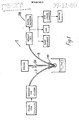
- a liquid drop analyser indicated generally by the reference numeral 1.
- Two radiation guides namely a delivery guide 2 and a receiver guide 3, in this embodiment formed by optical fibres, are mounted within a drop forming device, indicated generally by the reference numeral 10.
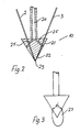
- the drop forming device 10 comprises a cone shaped body member 21 having a conical outer surface 22 terminating in a sharp apex 23, a sample liquid supply pipe 24 feeds liquid through internal ducts 25 onto the conical outer surface 22 from a syringe 26 to the drop forming device 10.
- the body 21 has a cone angle alpha (see Fig. 3) which is preferably in the range 45° to 70°.
- An advantage of forming a drop with a zero contact angle between the drop and the support surface is that in the measurement of drop times, drop weight, drop volumes or whatever other methods of analysis are used the corrections which are associated with other drop support systems such as the bare fibres themselves are not necessary.
- the radiation used is light and the sample liquid from the syringe 26 is delivered through the supply pipe 24 and ducts 25 onto the conical surface 22. Liquid travels down the conical surface 22 to form a drop indicated by the reference numeral 27 in Fig. 3. Light is delivered through the delivery guide 2 and from the drop 27 to the receiver guide 3 to a detector circuit 28 of the liquid drop analyser 1.
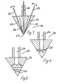
- Fig. 4 there is illustrated an alternative construction of drop forming device indicated generally by the reference numeral 30 in which parts similar to those described with reference to the previous drawings are identified by the same reference numerals.
- this embodiment there is a plurality of radially arranged ducts 25.
- Fig. 5 there is illustrated an alternative construction of drop forming device indicated generally by the reference numeral 40 and again parts similar to those described with reference to the previous drawings are identified by the same reference numerals.
- a plurality of circular grooves 41 are provided in the conical outer surface 22 for distribution of liquid around the body member 21.
- the grooves 41 cause liquid delivered down the conical surface 22 from the ducts 25 to coalesce into a ring and the ring of liquid then feeds the drop 27 being formed at the apex 23 in a more uniform and satisfactory manner.
- the signal derived from the liquid drop analyser 1 is a signal which has been reflected within the pendant drop 27 and can be a signal with a multiplicity of reflections. In some cases light is not reflected at the surface of the drop but may be absorbed within the drop, for example, by a fluorescent material which subsequently emits light and this emitted light is picked up by the receiver guide 3. Further, the light signal may in some cases be reflected from particulate material within the drop.
- Fig. 6(a) illustrates a typical signal derived, the two pulses A being the pulse received as the drop is fully formed and falls and the intermediate signal B is the signal that is achieved as the drop is being formed.
- FIG. 6(b) A typical signal trace derived in this case is shown in Fig. 6(b).
- the peaks B1, B2, B3 and B4 correspond to the signals received after one, two, three and four reflections respectively within the drop.
- This signal trace may be achieved by the use of a drop forming device illustrated in Fig. 7 and identified by the reference numeral 50, having a conical body member 51.
- a pair of radiation guides 52 and 53 are provided within sockets 54 and 55 respectively.
- the radiation guides 52 and 53 can thus be adjustably mounted on the body member 51 for variation of the angle at which radiation is delivered into or collected from a pendant drop.
- the supply pipe 24 delivers to an inline central bore 56 exiting at the lowermost portion of the body member 51 at 57. This particular construction of bore 56 has been found particularly suitable as a drop is formed in the best possible position for regular controlled formation.
- a drop forming device indicated generally by the reference numeral 60 having a body member 61 of frustro-conical shape.
- the frustro-conical shape is of no particular significance.
- the body member 61 terminates in a flat surface 62 into which projects the radiation guides 2 and 3 and a central supply pipe 63.
- a further drop forming device indicated generally by the reference numeral 70 in which parts similar to those described with reference to Fig. 8 are identified by the same reference numerals.
- the radiation guides 2, 3 diverge for transmission and collection of radiation adjacent an inner surface of a pendant drop 27.
- the path travelled by light through the drop 27 is indicated by the broken line 71.
- the advantage of this arrangement of radiation guides 2,3 is that information on conditions at the surface of a drop can be collected. It will be appreciated that this type of arrangement of the radiation guides may be incorporated in the conical drop forming devices described previously.
- FIG. 10 there is illustrated portion of a drop forming device indicated generally by the reference numeral 80 with a body member 81 formed by a ring with an inner drop supporting surface 82. Again parts similar to those described with reference to the previous drawings are identified by the same reference numerals.
- Fig. 11 there is illustrated an alternative construction of drop forming device indicated generally by the reference numeral 90 having a body member 91 in which is mounted a delivery radiation guide 92 formed from an optical fibre and a receiver radiation guide 93 formed from an optical fibre having a looped end 94 projecting out of the body member 91.
- This looped end 94 has its cladding or external coating removed to pick up or emit signals in the drop.
- Both ends of the receiver radiation guide 93 may be coupled one to a light source and one to a detector. Alternatively, both ends may be connected to separate detectors. In this case a different signal would be picked up by each detector and a differential detection system based on a comparison of the signals in each detector may in some cases be advantageous.
- a drop forming device indicated generally by the reference numeral 100 having a body member 101 with supply pipe 102 delivering to an inverted conical hole 103 into which also feeds radiation guides 104 and 105.
- a drop forming device indicated generally by the reference numeral 110 which is rotatable by gearing 111 and 112, parts similar to those described with reference to the previous drawings are identified by the same reference numerals.
- Fig. 14 in which there is a drop forming device indicated generally by the reference numeral 120 having a body member 121 with a central bore 122 for reception of a vibrator rod 123. It will be appreciated that many other alternative arrangements for vibrating the drop are possible.
- Fig. 15 there is illustrated the drop forming device 40 of Fig. 5 mounted between a pair of capacitor plates 125 and 126 powered by either AC or DC current from a power source 127.
- Fig. 16 illustrates the drop forming device 10 of Figs. 2 and 3 having a high tension rod 128 for bombarding the pendant drop 27 with electrons to charge the drop 27.
- a drop forming device indicated generally by the reference numeral 130 having a body member 131.
- the body member 131 has a central bore 132 fed from an electrolyte storage tank 133 in which is mounted an electrode 134.
- An electrode 134 At the bottom of the bore 132 is a porous plug 135.
- a liquid supply pipe 136 is provided.
- the electrode 134 allows a drop 27 to be charged with ions which produce changes in the shape of the drop 27 which can be used for measurement of various properties such as electro-chemical properties of the sample liquid.
- Fig. 18 there is illustrated the drop forming device 10 mounted within a solenoid 140 to provide a magnetic field. It will be appreciated the application of a magnetic field to a liquid which is either itself magnetic or contains magnetic particulate matter will be advantageous.
- a drop forming device indicated generally by the reference numeral 150 having a body member 151 and a central supply pipe 152 similar to those previously described for forming the pendant drop 27.
- a secondary liquid feed 153 which delivers through a bore 154 to the outer conical surface 155 of the body member 151.
- This secondary liquid feed is provided to deliver discrete quantities of, for example, surface active liquid to the liquid drop 27, obviously subsequent to that liquid drop 27 having been at least partially formed.
- a surface coating to the drop supporting surface, particularly for studying the interaction of solid surfaces with liquids.
- Such surface coatings include inter alia but not exclusively molecular coatings, ions or electric charge for example.
- Fig. 20 there is illustrated an alternative construction of drop forming device indicated generally by the reference numeral 160 having a body member 161 substantially similar to many of the body members hereinbefore described in which the outer conical surface is covered by a molecular coating 162. This would typically be a mono-layer of molecules such as a Langmuir-Blodgett film.
- two radiation guides are mounted on the body member.
- any desired number of radiation guides may be provided, one being the essential minimum.
- one or more guides for ultrasonic radiation may be provided on the body member in addition to or instead of the guides for electromagnetic radiation such as light.
Landscapes
- Chemical & Material Sciences (AREA)
- Health & Medical Sciences (AREA)
- General Physics & Mathematics (AREA)
- Physics & Mathematics (AREA)
- Life Sciences & Earth Sciences (AREA)
- Analytical Chemistry (AREA)
- Biochemistry (AREA)
- General Health & Medical Sciences (AREA)
- Immunology (AREA)
- Pathology (AREA)
- Chemical Kinetics & Catalysis (AREA)
- Clinical Laboratory Science (AREA)
- Investigating Or Analysing Materials By Optical Means (AREA)
- Sampling And Sample Adjustment (AREA)
Applications Claiming Priority (2)
| Application Number | Priority Date | Filing Date | Title |
|---|---|---|---|
| IE322089 | 1988-10-10 | ||
| IE322089 | 1988-10-10 |
Publications (1)
| Publication Number | Publication Date |
|---|---|
| EP0364203A1 true EP0364203A1 (de) | 1990-04-18 |
Family
ID=11038096
Family Applications (1)
| Application Number | Title | Priority Date | Filing Date |
|---|---|---|---|
| EP89310330A Withdrawn EP0364203A1 (de) | 1988-10-10 | 1989-10-10 | Vorrichtung zum Hervorbringen eines Flüssigkeitstropfens |
Country Status (2)
| Country | Link |
|---|---|
| EP (1) | EP0364203A1 (de) |
| JP (1) | JPH02257034A (de) |
Cited By (10)
| Publication number | Priority date | Publication date | Assignee | Title |
|---|---|---|---|---|
| EP0588968A4 (en) * | 1991-06-13 | 1994-06-22 | Abbott Lab | Liquid dispensing mechanism |
| JPH07506681A (ja) * | 1992-06-04 | 1995-07-20 | アグファ−ゲヴェルト ナームロゼ ベンノートチャップ | 架橋した結合剤系を含有する光導電性記録材料 |
| WO1999030169A1 (de) * | 1997-12-08 | 1999-06-17 | MAX-PLANCK-Gesellschaft zur Förderung der Wissenschaften e.V. | Vorrichtung und verfahren zur bildaufnahme an tropfenerzeugenden dispensierköpfen |
| WO2000025923A1 (en) * | 1998-11-04 | 2000-05-11 | Biorobotics Ltd. | Liquid transfer system |
| ES2153296A1 (es) * | 1998-07-30 | 2001-02-16 | Univ Granada | Capilares coaxiales y procedimiento de intercambio para balanza de superficie de penetracion. |
| FR2829576A1 (fr) * | 2001-09-12 | 2003-03-14 | Bio Merieux | Procede et dispositif d'isolement et/ou determination d'un analyte |
| WO2006087390A1 (en) * | 2005-02-18 | 2006-08-24 | Norman Mcmillan | A tensiographic drophead |
| WO2007131945A2 (en) | 2006-05-12 | 2007-11-22 | Carl Stuart Limited | Microvolume analysis system |
| CN104792667A (zh) * | 2015-03-27 | 2015-07-22 | 常州大学 | 一种表面张力高温悬滴测量支架 |
| EP3023152A1 (de) * | 2014-11-20 | 2016-05-25 | Friedrich-Alexander-Universität Erlangen-Nürnberg | Verfahren zur Herstellung einer flüssigen Probe zur Analyse durch Strahlung |
Families Citing this family (1)
| Publication number | Priority date | Publication date | Assignee | Title |
|---|---|---|---|---|
| JP5420725B2 (ja) * | 2011-06-28 | 2014-02-19 | 株式会社イマック | 光学測定装置 |
Citations (3)
| Publication number | Priority date | Publication date | Assignee | Title |
|---|---|---|---|---|
| GB2105034A (en) * | 1981-09-04 | 1983-03-16 | Westinghouse Electric Corp | Fiber optic impurity detector |
| EP0144928A2 (de) * | 1983-12-08 | 1985-06-19 | Hoechst Aktiengesellschaft | Photometerkopf für kleine Messvolumina |
| EP0286419A2 (de) * | 1987-04-10 | 1988-10-12 | McMillan, Norman | Verfahren und Gerät zur Messung der Eigenschaften einer Flüssigkeit |
-
1989
- 1989-10-10 EP EP89310330A patent/EP0364203A1/de not_active Withdrawn
- 1989-10-11 JP JP27053189A patent/JPH02257034A/ja active Pending
Patent Citations (3)
| Publication number | Priority date | Publication date | Assignee | Title |
|---|---|---|---|---|
| GB2105034A (en) * | 1981-09-04 | 1983-03-16 | Westinghouse Electric Corp | Fiber optic impurity detector |
| EP0144928A2 (de) * | 1983-12-08 | 1985-06-19 | Hoechst Aktiengesellschaft | Photometerkopf für kleine Messvolumina |
| EP0286419A2 (de) * | 1987-04-10 | 1988-10-12 | McMillan, Norman | Verfahren und Gerät zur Messung der Eigenschaften einer Flüssigkeit |
Non-Patent Citations (1)
| Title |
|---|
| REVIEW OF SCIENTIFIC INSTRUMENTS, vol. 49, no. 8, August 1978, pages 1090-1092, American Institute of Physics; N. ABUAF et al.: "Optical probe for local void fraction and interface velocity measurements" * |
Cited By (19)
| Publication number | Priority date | Publication date | Assignee | Title |
|---|---|---|---|---|
| EP0588968A4 (en) * | 1991-06-13 | 1994-06-22 | Abbott Lab | Liquid dispensing mechanism |
| JPH07506681A (ja) * | 1992-06-04 | 1995-07-20 | アグファ−ゲヴェルト ナームロゼ ベンノートチャップ | 架橋した結合剤系を含有する光導電性記録材料 |
| WO1999030169A1 (de) * | 1997-12-08 | 1999-06-17 | MAX-PLANCK-Gesellschaft zur Förderung der Wissenschaften e.V. | Vorrichtung und verfahren zur bildaufnahme an tropfenerzeugenden dispensierköpfen |
| US6851784B1 (en) | 1997-12-08 | 2005-02-08 | Max-Planck-Gesellschaft Zur Forderung Der Wissenschaften E.V. | Method and device for recording an image on drop-producing dispensing heads |
| ES2153296A1 (es) * | 1998-07-30 | 2001-02-16 | Univ Granada | Capilares coaxiales y procedimiento de intercambio para balanza de superficie de penetracion. |
| US6723569B1 (en) | 1998-11-04 | 2004-04-20 | Genomic Solutions Acquisitions Limited | Liquid transfer system |
| WO2000025923A1 (en) * | 1998-11-04 | 2000-05-11 | Biorobotics Ltd. | Liquid transfer system |
| GB2360957A (en) * | 1998-11-04 | 2001-10-10 | Biorobotics Ltd | Liquid transfer system |
| GB2360957B (en) * | 1998-11-04 | 2003-01-08 | Biorobotics Ltd | Use of a dropping tool |
| WO2003022436A1 (fr) * | 2001-09-12 | 2003-03-20 | bioMérieux | Procede et dispositif d'isolement et/ou determination d'un analyte |
| FR2829576A1 (fr) * | 2001-09-12 | 2003-03-14 | Bio Merieux | Procede et dispositif d'isolement et/ou determination d'un analyte |
| WO2006087390A1 (en) * | 2005-02-18 | 2006-08-24 | Norman Mcmillan | A tensiographic drophead |
| US7786441B2 (en) * | 2005-02-18 | 2010-08-31 | Mcmillan Norman | Tensiographic drophead |
| AU2006215602B2 (en) * | 2005-02-18 | 2012-11-01 | Michael Baker | A tensiographic drophead |
| WO2007131945A2 (en) | 2006-05-12 | 2007-11-22 | Carl Stuart Limited | Microvolume analysis system |
| WO2007131945A3 (en) * | 2006-05-12 | 2008-03-13 | Carl Stuart Ltd | Microvolume analysis system |
| EP3023152A1 (de) * | 2014-11-20 | 2016-05-25 | Friedrich-Alexander-Universität Erlangen-Nürnberg | Verfahren zur Herstellung einer flüssigen Probe zur Analyse durch Strahlung |
| CN104792667A (zh) * | 2015-03-27 | 2015-07-22 | 常州大学 | 一种表面张力高温悬滴测量支架 |
| CN104792667B (zh) * | 2015-03-27 | 2017-10-20 | 常州大学 | 一种表面张力高温悬滴测量支架 |
Also Published As
| Publication number | Publication date |
|---|---|
| JPH02257034A (ja) | 1990-10-17 |
Similar Documents
| Publication | Publication Date | Title |
|---|---|---|
| EP0364203A1 (de) | Vorrichtung zum Hervorbringen eines Flüssigkeitstropfens | |
| Kuffler et al. | The number of transmitter molecules in a quantum: an estimate from iontophoretic application of acetylcholine at the neuromuscular synapse. | |
| US11670478B2 (en) | Multi-degree-of-freedom sample holder | |
| FI72608C (fi) | Foerfarande och anordning foer instaellning av droppformningspunkten i sprutvaetskan hos en elektrostatisk sorteringsanordning. | |
| PT81736B (pt) | Aparelho de atomizacao electrostatica e processo utilizando esse aparelho | |
| DK146984B (da) | Apparat til undersoegelse af i en vaeske suspenderede partikler | |
| DE3310551C2 (de) | Teilchenuntersuchungsvorrichtung zur Untersuchung von in einer Flüssigkeit suspendierten Teilchen | |
| DE102017004475A1 (de) | Messgerät zur Messung von Oberflächenprofilen in Hohlräumen | |
| US4914307A (en) | Optoelectronic device for contactless measurement of the dimensions of objects | |
| EP0310348A2 (de) | Verfahren und Gerät zur Messung von Fasern in der Luft | |
| CN1015827B (zh) | 测量光纤折射率分布图的方法 | |
| US4264206A (en) | Dust particle analyzer | |
| KR950000937B1 (ko) | 풀림시 광섬유 감시 방법 | |
| CN206497055U (zh) | 光纤型针孔检测装置 | |
| EP0183798A1 (de) | Optische systeme für fluss-cytometer | |
| US6439068B2 (en) | Process and device for determining the volume of liquid droplets | |
| CN217005714U (zh) | 激光直径仪 | |
| JPS6345553A (ja) | レ−ザ−ドップラ−電気泳動システム用マイクロ電気泳動セル | |
| DE4119147A1 (de) | Nachweisgeraet fuer aktiv abstrahlende flaechen von ultraschall-schwingern | |
| US11054409B2 (en) | Method and device for automatically determining the position of a microsystem for manipulating a spherical microobject | |
| DD227044A1 (de) | Verfahren und vorrichtung zur erfassung des stoffwechselzustandes von lebenden organen | |
| US6721049B1 (en) | Device for efficient light collection from a sample | |
| JPS646700B2 (de) | ||
| CN114754817A (zh) | 海洋参数测量设备、测量探头、探头投弃装置和测量主机 | |
| CN1012283B (zh) | 超微弱发光探测装置 |
Legal Events
| Date | Code | Title | Description |
|---|---|---|---|
| PUAI | Public reference made under article 153(3) epc to a published international application that has entered the european phase |
Free format text: ORIGINAL CODE: 0009012 |
|
| AK | Designated contracting states |
Kind code of ref document: A1 Designated state(s): AT BE CH DE ES FR GB GR IT LI LU NL SE |
|
| 17P | Request for examination filed |
Effective date: 19901210 |
|
| STAA | Information on the status of an ep patent application or granted ep patent |
Free format text: STATUS: THE APPLICATION IS DEEMED TO BE WITHDRAWN |
|
| 18D | Application deemed to be withdrawn |
Effective date: 19920505 |