EP0364232A1 - Fluidpumpe - Google Patents
Fluidpumpe Download PDFInfo
- Publication number
- EP0364232A1 EP0364232A1 EP89310382A EP89310382A EP0364232A1 EP 0364232 A1 EP0364232 A1 EP 0364232A1 EP 89310382 A EP89310382 A EP 89310382A EP 89310382 A EP89310382 A EP 89310382A EP 0364232 A1 EP0364232 A1 EP 0364232A1
- Authority
- EP
- European Patent Office
- Prior art keywords
- fluid
- vessel
- valve
- conduit
- gas discharge
- Prior art date
- Legal status (The legal status is an assumption and is not a legal conclusion. Google has not performed a legal analysis and makes no representation as to the accuracy of the status listed.)
- Withdrawn
Links
Images


Classifications
-
- F—MECHANICAL ENGINEERING; LIGHTING; HEATING; WEAPONS; BLASTING
- F17—STORING OR DISTRIBUTING GASES OR LIQUIDS
- F17C—VESSELS FOR CONTAINING OR STORING COMPRESSED, LIQUEFIED OR SOLIDIFIED GASES; FIXED-CAPACITY GAS-HOLDERS; FILLING VESSELS WITH, OR DISCHARGING FROM VESSELS, COMPRESSED, LIQUEFIED, OR SOLIDIFIED GASES
- F17C9/00—Methods or apparatus for discharging liquefied or solidified gases from vessels not under pressure
Definitions
- the present invention relates to a fluid pump for feeding a fluid to a remote location, and more particularly, but not exclusively, to a fluid pump for feeding relatively small quantities of cryogenic liquid at low pressures.
- the performance of some electronic devices can be improved by cooling them to cryogenic temperatures.
- Such cooling can be achieved by the use of a cryogenic fluid such as liquid or gaseous Nitrogen or Helium.
- a cryogenic fluid such as liquid or gaseous Nitrogen or Helium.
- an electronic device is brought into thermal contact with fluid held in a relatively small container. As the device is cooled, fluid is evaporated which must then be replenished from a remotely located reservoir.
- the fluid pressure in the container is generally low, typically atmospheric, whereas the pressure in the reservoir may be the same or higher.
- Conventional pumps are unable to efficiently provide the automatic, low volume, low pressure and low temperature operation required by such applications.
- the present invention provides a pump for feeding a fluid from a reservoir of said fluid to a location remote from said pump, including a vessel for holding said fluid and having fluid inlet means for receiving fluid from said reservoir, conduit means communicating with the inside of said vessel for feeding said fluid from said vessel to said location, characterized by heating means for evaporating said fluid within said vessel to create a gas pressure within said vessel for forcing said fluid to flow along said conduit, and gas discharge valve means located within said vessel and operable in response to the level of said fluid within said vessel for opening and closing a gas discharge outlet whereby said gas discharge outlet is opened when said fluid falls below a predetermined level within said vessel thereby relieving said gas pressure within said vessel and allowing fluid to enter said vessel from said reservoir through said inlet valve means.
- FIG. 1 shows a system utilizing a pump 10 according to one embodiment of the present invention.
- a container 12 houses an electronic device 14 immersed in a cooling fluid 16 which is preferably a cryogenic fluid such as liquid Nitrogen or Helium. Cooling fluid is delivered by pump 10 to the container 12 from a reservoir 18 containing the cooling fluid 16.
- a cryogenic fluid such as liquid Nitrogen or Helium.
- Pump 10 comprises a vessel 20 for holding cooling fluid to be delivered to container 12. As shown, vessel 20 is submerged in the fluid 16 within reservoir 18. Cooling fluid is received by vessel 20 through a fluid inlet 22 near the bottom 24 of vessel 20. The gas of evaporated fluid is released (under certain operating conditions to be discussed more fully hereinafter) by vessel 20 through a gas discharge outlet 26 near top 28 of vessel 20. A conduit 30 conducts cooling fluid from inside vessel 20 to container 12 by means to be discussed more fully hereinafter.
- Container 12 also includes a mechanical liquid level controller 36 which senses the level of fluid within container 12 and restricts the flow of cooling fluid through conduit 30 when the fluid within container 12 rises to a predetermined level. In a preferred embodiment, controller 36 is a conventional float valve. Also shown extending through top 28 of vessel 20 is the outlet end 40 of a pressure relief line, and contact terminals 42 for a heater within vessel 20.
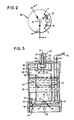
- FIG. 2 shows a top view of vessel 20 with like numbers representing the same elements as described with respect to Figure 1.
- FIG. 3 shows a cross sectional view of vessel 20 taken along the line 3-3 in Figure 2.
- An inlet valve 44 prevents fluid from flowing out of vessel 20 through fluid inlets 22.
- Valve 44 is a ball check valve having a ball 46 which covers orifice 48 when no fluid is entering vessel 20 but which is dislodged when fluid is entering vessel 20. In the latter condition a cage 50 prevents ball 46 from escaping.
- a gas discharge valve 52 responds to the level of fluid within vessel 20 for opening and closing gas discharge outlet 26.
- Gas discharge valve 52 includes a dynamic valve member 54, a magnet 56, a float 58 with attached weight 61, a movable shaft 60, and guide means 70.
- Dynamic valve member 54, magnet 56 and float 58 are vertically aligned and fixed to vertically movable shaft 60.
- Guide means 70 includes a boss 72 for receiving the lower end of shaft 60 to prevent lateral movement of valve 52.
- Dynamic valve member 54 is a ball which closes gas discharge outlet 26 by covering orifice 64 in outlet 26.
- Figure 3 shows gas discharge outlet 26 closed ( Figure 4 shows it open).
- Magnet 56 is positioned between an upper attraction plate 66 and a lower attraction plate 68. The spacing between plates 66 and 68 and their relationship to magnet 56 and valve member 54 is such that when gas discharge outlet 26 is closed, magnet 56 will be proximate to but spaced apart from upper attraction plate 66 by an air gap 67. Air gap 67 is provided in order to ensure a complete seal of gas discharge outlet 26 and to better regulate the closure force.
- a spacer 69 of about the same thickness as air gap 67 is attached to the bottom of magnet 56 so that magnet 56 is proximate to but not directly in contact with lower plate 68 when outlet 26 is open. Both the air gap 67 and spacer 69 are effective to balance the magnetic force with the float force.
- Float 58 provides an increasing upward force on shaft 60, as a result of increased buoyancy, in response to a rising fluid level within vessel 20. At some fluid level this upward force overcomes the attractive force between magnet 56 and lower attraction plate 68 and combines with the attractive force between magnet 56 and upper attraction plate 66 to move gas discharge valve 52 to the closed position of Figure 3.
- float 58 with weight 61 provides an increasing downward force on shaft 60, as its combined weight exceeds its buoyancy in response to a falling fluid level within vessel 20. At some fluid level this downward force overcomes the attractive force between magnet 56 and upper attraction plate 66 and combines with the attractive force between magnet 56 and lower attraction plate 68 to move gas discharge valve 52 to its open position (shown in Figure 4).
- Figure 3 also shows an electric resistance heater 74 within vessel 20 connected to contact terminals 42 and positioned in the lower region of vessel 20.
- a wire 32 having conductors for supplying electric current to heater 74 is also connected to contact terminals 42.
- the conductors extend from a current source 34 outside reservoir 18 to contact terminals 42.
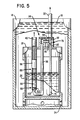
- FIG. 5 shows another view of vessel 20, taken along the line 5-5 in Figure 2.
- Conduit 30 which conducts fluid from inside vessel 20 to its destination has an inlet end 76 for receiving the fluid. Inlet end 76 is located within vessel 20 and proximate to the bottom 24 of vessel 20. Conduit 30 exits vessel 20 through top 28.
- An outlet valve 78 is provided to prevent fluid from flowing back into vessel 20 from conduit 30.
- Valve 78 is a ball check valve having a ball 80 which covers orifice 82 when no fluid is exiting vessel 20 thereby preventing backflow but which is dislodged when fluid is exiting vessel 20 to permit flow therethrough.
- a pressure regulator 84 limits the pressure within conduit 30.
- Pressure regulator 84 comprises a pressure relief line 86, a pressure relief valve 88 in line 86 and biasing means in the form of a weight 90 for providing a predetermined closure force on valve 88.
- Line 86 taps into conduit 30 at opening 92 on the destination side of outlet valve 78 and includes an elbow or short cross member 94.
- Pressure relief line 86 is generally U-shaped with two vertically positioned legs 96 and 98. Leg 96 receives fluid from conduit 30 through cross member 94. Leg 98 discharges excessively pressurized fluid through valve 88 into reservoir 18.
- Pressure relief valve 88 is a ball check valve having a ball 100 which covers orifice 102 when no fluid is exiting line 86 but which is dislodged when fluid is exiting line 86.
- Valve 88 and weight 90 are disposed in leg 98 with weight 90 on top of ball 100.
- current source 34 provides a current flow in wire 32 ( Figure 1) to heater 74.
- Heater 74 then causes fluid in vessel 20 to evaporate, thereby producing gas ( Figure 3).
- gas discharge valve 52 will remain closed and the gas of evaporation will create a pressure head in the upper region 102. This will produce a fluid flow through conduit 30 as the pressure head forces down the fluid level ( Figure 5).
- liquid level controller 36 will allow the fluid to enter container 12 ( Figure 1). When the level of fluid within container 12 rises to a predetermined level, controller 36 will cut off the flow into container 12 and the cooling fluid will be diverted as will be explained more fully hereafter.
- conduit 30 Although fluid will be pumped through conduit 30 as long as gas discharge valve 52 is closed and heater 74 is evaporating fluid, the pressure within conduit 30 is limited by pressure regulator 84. The maximum allowable pressure is determined by weight 90. As soon as the pressure force within conduit 30 exceeds such weight fluid will be diverted from conduit 30 through pressure relief valve 88 into reservoir 18.
Landscapes
- Engineering & Computer Science (AREA)
- Mechanical Engineering (AREA)
- General Engineering & Computer Science (AREA)
- Filling Or Discharging Of Gas Storage Vessels (AREA)
- Check Valves (AREA)
Applications Claiming Priority (2)
| Application Number | Priority Date | Filing Date | Title |
|---|---|---|---|
| US07/258,261 US4852357A (en) | 1988-10-14 | 1988-10-14 | Cryogenic liquid pump |
| US258261 | 1994-06-08 |
Publications (1)
| Publication Number | Publication Date |
|---|---|
| EP0364232A1 true EP0364232A1 (de) | 1990-04-18 |
Family
ID=22979790
Family Applications (1)
| Application Number | Title | Priority Date | Filing Date |
|---|---|---|---|
| EP89310382A Withdrawn EP0364232A1 (de) | 1988-10-14 | 1989-10-11 | Fluidpumpe |
Country Status (2)
| Country | Link |
|---|---|
| US (1) | US4852357A (de) |
| EP (1) | EP0364232A1 (de) |
Cited By (5)
| Publication number | Priority date | Publication date | Assignee | Title |
|---|---|---|---|---|
| DE4120372A1 (de) * | 1991-06-20 | 1992-12-24 | Tzn Forschung & Entwicklung | Verfahren zur erzeugung hoher fluessigkeitsdruckimpulse, vorrichtung zur druchfuehrung des verfahrens und verwendung der vorrichtung als hochdruckreiniger |
| RU2499180C2 (ru) * | 2011-11-09 | 2013-11-20 | Открытое акционерное общество "Ракетно-космическая корпорация "Энергия" имени С.П. Королева" | Термокомпрессионное устройство |
| RU2508497C2 (ru) * | 2011-12-28 | 2014-02-27 | Открытое акционерное общество "Ракетно-космическая корпорация "Энергия" имени С.П. Королева" | Термокомпрессионное устройство |
| RU2514335C2 (ru) * | 2012-07-23 | 2014-04-27 | Открытое акционерное общество "Ракетно-космическая корпорация "Энергия" имени С.П. Королева" | Термокомпрессионное устройство |
| RU2527227C2 (ru) * | 2012-03-29 | 2014-08-27 | Открытое акционерное общество "Ракетно-космическая корпорация "Энергия" имени С.П. Королева" | Термокомпрессионное устройство |
Families Citing this family (5)
| Publication number | Priority date | Publication date | Assignee | Title |
|---|---|---|---|---|
| US6295840B1 (en) | 2000-11-15 | 2001-10-02 | Air Products And Chemicals, Inc. | Pressurized liquid cryogen process |
| FR2881216B1 (fr) * | 2005-01-27 | 2007-04-06 | Org Europeene De Rech | Installation de refroidissement cryogenique pour dispositif supraconducteur |
| FR2993255B1 (fr) * | 2012-07-10 | 2015-07-03 | Turbomeca | Dispositif d'emplissage pour reservoir de fluide |
| EP2690383A1 (de) * | 2012-07-27 | 2014-01-29 | Embl Heidelberg | Kühlen eines Dewarbehälters mit einem eisfreien Kühlmittel und zwecks eines kurzen Probenzugangs |
| WO2014091866A1 (ja) * | 2012-12-14 | 2014-06-19 | イーグル工業株式会社 | 液体供給システム |
Citations (2)
| Publication number | Priority date | Publication date | Assignee | Title |
|---|---|---|---|---|
| US3834835A (en) * | 1972-11-29 | 1974-09-10 | Gen Electric | Double valve vapor push pump |
| US4556368A (en) * | 1983-12-02 | 1985-12-03 | Soltrac, Inc. | Vapor pressure pump |
Family Cites Families (19)
| Publication number | Priority date | Publication date | Assignee | Title |
|---|---|---|---|---|
| US1606356A (en) * | 1924-10-06 | 1926-11-09 | Charles A Fisher | Liquid purification and liquid-level control |
| US1745762A (en) * | 1928-12-10 | 1930-02-04 | Hartford Empire Co | Magnetic float valve |
| US1951758A (en) * | 1930-04-15 | 1934-03-20 | Charles L Jones | Method of and apparatus for supplying carbon dioxide gas |
| US2454934A (en) * | 1947-01-24 | 1948-11-30 | John A Mathis | Electrical oxygen vaporizer and protecting cover |
| US2530382A (en) * | 1948-05-05 | 1950-11-21 | Downs Orville | Heating water by electricity |
| US2999509A (en) * | 1956-12-12 | 1961-09-12 | Hankison Corp | Device for automatically valving liquid |
| US3049887A (en) * | 1960-02-15 | 1962-08-21 | Gen Dynamics Corp | Liquid control device |
| US3202174A (en) * | 1963-04-25 | 1965-08-24 | Bruner Corp | Float actuated fill valve |
| US3233625A (en) * | 1963-11-22 | 1966-02-08 | Houston Company | Magnetically operated valve |
| US3440829A (en) * | 1963-12-11 | 1969-04-29 | Lab For Electronics Inc | Liquified gas delivery system |
| US3234746A (en) * | 1964-04-28 | 1966-02-15 | Olin Mathieson | Process and apparatus for the transfer of liquid carbon dioxide |
| US3260061A (en) * | 1964-12-16 | 1966-07-12 | Lox Equip | Flow system for cryogenic materials |
| US3399691A (en) * | 1966-08-15 | 1968-09-03 | Gen Electric | Liquid transfer system |
| US3397870A (en) * | 1966-08-19 | 1968-08-20 | Mccann S Engineering & Mfg Co | Carbonator tank |
| US3729946A (en) * | 1971-05-26 | 1973-05-01 | A Massey | Cryogenic liquid handling system |
| US3941509A (en) * | 1974-08-02 | 1976-03-02 | Fluid Systems Research, Inc. | Pumping system |
| US4360038A (en) * | 1980-08-18 | 1982-11-23 | Sherwood Selpac Corporation | Magnetically-operated valve |
| DE3234457C2 (de) * | 1982-09-17 | 1984-09-20 | C. Reichert Optische Werke Ag, Wien | Kühlbad zum raschen Abkühlen von Proben, insbesondere zur Kryofixation biologischer Objekte für eine nachfolgende licht- oder elektronenoptische Untersuchung |
| FR2539211B1 (fr) * | 1983-01-12 | 1988-02-26 | Air Liquide | Dispositif de distribution de liquide cryogenique |
-
1988
- 1988-10-14 US US07/258,261 patent/US4852357A/en not_active Expired - Fee Related
-
1989
- 1989-10-11 EP EP89310382A patent/EP0364232A1/de not_active Withdrawn
Patent Citations (2)
| Publication number | Priority date | Publication date | Assignee | Title |
|---|---|---|---|---|
| US3834835A (en) * | 1972-11-29 | 1974-09-10 | Gen Electric | Double valve vapor push pump |
| US4556368A (en) * | 1983-12-02 | 1985-12-03 | Soltrac, Inc. | Vapor pressure pump |
Cited By (5)
| Publication number | Priority date | Publication date | Assignee | Title |
|---|---|---|---|---|
| DE4120372A1 (de) * | 1991-06-20 | 1992-12-24 | Tzn Forschung & Entwicklung | Verfahren zur erzeugung hoher fluessigkeitsdruckimpulse, vorrichtung zur druchfuehrung des verfahrens und verwendung der vorrichtung als hochdruckreiniger |
| RU2499180C2 (ru) * | 2011-11-09 | 2013-11-20 | Открытое акционерное общество "Ракетно-космическая корпорация "Энергия" имени С.П. Королева" | Термокомпрессионное устройство |
| RU2508497C2 (ru) * | 2011-12-28 | 2014-02-27 | Открытое акционерное общество "Ракетно-космическая корпорация "Энергия" имени С.П. Королева" | Термокомпрессионное устройство |
| RU2527227C2 (ru) * | 2012-03-29 | 2014-08-27 | Открытое акционерное общество "Ракетно-космическая корпорация "Энергия" имени С.П. Королева" | Термокомпрессионное устройство |
| RU2514335C2 (ru) * | 2012-07-23 | 2014-04-27 | Открытое акционерное общество "Ракетно-космическая корпорация "Энергия" имени С.П. Королева" | Термокомпрессионное устройство |
Also Published As
| Publication number | Publication date |
|---|---|
| US4852357A (en) | 1989-08-01 |
Similar Documents
| Publication | Publication Date | Title |
|---|---|---|
| EP0364232A1 (de) | Fluidpumpe | |
| US6553974B1 (en) | Engine fuel system with a fuel vapor separator and a fuel vapor vent canister | |
| KR970704953A (ko) | 전자시계식 오일 레벨 조절기 | |
| EP0024771A1 (de) | Sicherheitsvorrichtung für eine mit einer unter Druck stehenden Flüssigkeit gefüllte Wärmetauscheranlage | |
| PL120593B1 (en) | Valve | |
| US4345879A (en) | Hydraulic switch for a pump | |
| US4680091A (en) | Apparatus for the continuous vacuum cleaning of oil | |
| WO2016191721A2 (en) | Fluid release valve | |
| US5431546A (en) | Apparatus for intermittent transfer of fluid having vapor trap seal and vapor escape means | |
| CS195285B2 (en) | Pressure compensating apparatus for heating systems | |
| US5176167A (en) | Control valve | |
| KR101405313B1 (ko) | 고속 압력 밸브 | |
| US6552284B1 (en) | Water pump low pressure cutoff switch | |
| US4540342A (en) | Hydraulic switch | |
| US3834835A (en) | Double valve vapor push pump | |
| US3195557A (en) | Float actuated gas vent | |
| JP3379856B2 (ja) | 液位制御方法およびその制御装置 | |
| US5174944A (en) | Apparatus for separating gas from a liquid | |
| US4909038A (en) | Control system for dispensing a cryogenic fluid | |
| US4289451A (en) | External tank level control system | |
| US2911916A (en) | Valve for direct pressure shallow well pumping system | |
| US2264385A (en) | Liquid conditioning system | |
| US4739791A (en) | Fluid collection container particularly useful in suction pumps | |
| EP0065847A1 (de) | Flüssigkeitsniveauregelung | |
| US20050089420A1 (en) | Circulation pump |
Legal Events
| Date | Code | Title | Description |
|---|---|---|---|
| PUAI | Public reference made under article 153(3) epc to a published international application that has entered the european phase |
Free format text: ORIGINAL CODE: 0009012 |
|
| STAA | Information on the status of an ep patent application or granted ep patent |
Free format text: STATUS: THE APPLICATION HAS BEEN WITHDRAWN |
|
| AK | Designated contracting states |
Kind code of ref document: A1 Designated state(s): DE FR GB |
|
| 18W | Application withdrawn |
Withdrawal date: 19900410 |