EP0364332B1 - Behälter für die Aufbewahrung und zum Festhalten einer Computer-Spule - Google Patents
Behälter für die Aufbewahrung und zum Festhalten einer Computer-Spule Download PDFInfo
- Publication number
- EP0364332B1 EP0364332B1 EP89402720A EP89402720A EP0364332B1 EP 0364332 B1 EP0364332 B1 EP 0364332B1 EP 89402720 A EP89402720 A EP 89402720A EP 89402720 A EP89402720 A EP 89402720A EP 0364332 B1 EP0364332 B1 EP 0364332B1
- Authority
- EP
- European Patent Office
- Prior art keywords
- cover
- spring catch
- slide
- post
- dish
- Prior art date
- Legal status (The legal status is an assumption and is not a legal conclusion. Google has not performed a legal analysis and makes no representation as to the accuracy of the status listed.)
- Expired - Lifetime
Links
- 230000000452 restraining effect Effects 0.000 title 1
- 238000005452 bending Methods 0.000 claims description 4
- 230000003100 immobilizing effect Effects 0.000 claims description 4
- 238000005192 partition Methods 0.000 claims description 3
- 230000013011 mating Effects 0.000 claims 1
- 230000036961 partial effect Effects 0.000 description 3
- 238000004519 manufacturing process Methods 0.000 description 2
- 210000002445 nipple Anatomy 0.000 description 2
- 238000010276 construction Methods 0.000 description 1
- 230000000694 effects Effects 0.000 description 1
- 230000002427 irreversible effect Effects 0.000 description 1
- 230000000670 limiting effect Effects 0.000 description 1
- 239000000463 material Substances 0.000 description 1
- 239000002991 molded plastic Substances 0.000 description 1
- 238000000465 moulding Methods 0.000 description 1
- 239000004033 plastic Substances 0.000 description 1
- 230000002829 reductive effect Effects 0.000 description 1
- 230000001960 triggered effect Effects 0.000 description 1
Images

Classifications
-
- G—PHYSICS
- G11—INFORMATION STORAGE
- G11B—INFORMATION STORAGE BASED ON RELATIVE MOVEMENT BETWEEN RECORD CARRIER AND TRANSDUCER
- G11B23/00—Record carriers not specific to the method of recording or reproducing; Accessories, e.g. containers, specially adapted for co-operation with the recording or reproducing apparatus ; Intermediate mediums; Apparatus or processes specially adapted for their manufacture
- G11B23/02—Containers; Storing means both adapted to cooperate with the recording or reproducing means
- G11B23/027—Containers for single reels or spools
Definitions
- the present invention relates to a box intended to contain and immobilize a computer coil.
- Such a box is known in particular from French Patent No. 2,455,554. It comprises a body in which came from molding a central stud and a sleeve concentric therewith.
- the box also includes a cover closing the body by trapping the coil, the hub of which is centered on a single immobilizing ring surrounding the sleeve.
- the cover has a central bowl formed on its outer face which fits into the sleeve of the body and on said stud and delimits a housing intended to receive a locking device cooperating with this stud.
- the locking device is constituted by a single trigger covering the nipple and guided in translation between the bottom of the central bowl of the cover and a cover, which is fitted and fixed after mounting of the trigger in said bowl.
- This trigger and the body stud comprise conjugate engagement means capable of being engaged by a leaf spring forming a body with said trigger and bearing on the side wall of the bowl to cause the engagement sliding.
- This known box has the disadvantage of having four separate parts: the body, the cover, the trigger and the cover, therefore requiring four manufacturing operations with four different molds.
- the present invention therefore aims to simplify the design and construction of the locking device, as well as the assembly of the components, to reduce the number of these from four to three by manufacturing them only in plastic material, to eliminate the means subsidiary assembly by adopting a irreversible interlocking system and make assembly easy, quick and achievable by an automatic machine. Consequently, the box can be produced in large series at a low cost price and with a reduced investment in tools.
- guide means are provided on the trigger in order to be able to engage, during a trigger sliding, in guide means provided in the bowl, the latter also acting as means retaining the trigger in the bowl.
- said trigger forms a body with a flexible stop which can be deformed in a plane perpendicular to the sliding direction and which cooperates with a stopper of the bowl limiting the interlocking stroke, this stopper and this stopper having inclined ramps causing erasure by bending of said stopper during mounting of the trigger in the housing of the cover separate from the body, by sliding in the triggering direction, the stopper being placed after crossing the stopper facing the latter to determine the engagement position and make the trigger captive of the lid.
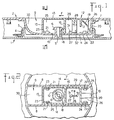
- the box has a body 1 and a cover 2 intended to contain a computer coil, not shown, and to immobilize it when they are locked one on the other.
- the body 1 has an internal protruding tubular sleeve 3 surrounded by a single ring 4 provided for immobilizing the hub of the coil.
- the body also has an internal projection, at the center of the sleeve 3, a stud 5 comprising a prominent extreme collar 6 intended for locking the cover 2 on this body 1.
- the cover 2 has in hollow a bowl 7 formed on its outer face and fitting into the sleeve 3 of the body 1, without however coming into contact with it when the box is closed.
- Two parallel partitions 8 are integral with the bottom of the bowl 7 and, with the edges of the latter, delimit a housing 9 open to the outside and into which opens a central hole 10 formed in the bottom 11 of the bowl for passage nipple 5.
- a trigger 12 capable of sliding in a direction parallel to the plane of the cover and which, like the body 1 and the cover 2, consists of a molded plastic.
- the trigger 12 has an upper wall 13 integral with two longitudinal walls 14 and transverse elements 15 to 17. The longitudinal walls are arranged against the partitions 8 of the cover.
- the element 15 is a front wall descending to the bottom 11.
- the element 16 is an intermediate bar which also descends to the bottom 11 and has a projecting tooth 18 capable of engaging under the collar 6 of the stud 5 for lock the cover 2 on the body 1.
- the element 17 is a rib forming a body with a leaf spring 19 intended by bearing on the wall 20 of the bowl to push the trigger in the direction of engagement defined by the arrow F .
- the bottom 11 of the bowl 7 has projecting two front elements 21 and two rear elements 22 of slide in which are ledges or slides 23 and 24 respectively of the trigger 12.
- the edges 23 extend along the longitudinal walls 14 from the front wall 15 and are located, like the slides 21 moreover, in a recess 25 delimited above the bottom 11, by the trigger 12 between its wall 15 and its bar 16.
- the flanges 24 extend along the longitudinal walls 14 from the rear wall 17 and are located, like the slides 22 moreover, in a recess 26 delimited above the bottom 11, by the trigger 12 between its wall 17 and the wall 20 of the bowl.
- the recess 26 is covered by the upper wall 13 of the trigger in its entirety when said trigger is triggered (the tooth 18 being out of engagement with the flange 6) and the box is open; the recess 26 is only partially covered by the upper wall 13 when the trigger is engaged as shown in Figure 1 (the tooth 18 is engaged with the flange 6) and the box is closed and locked.
- the means for guiding the trigger are practically inaccessible in these two engagement and disengagement positions.
- the bottom 11 of the bowl and the upper wall 13 of the trigger 12 have a stopper 27 and a flexible stop 28 conjugate projecting towards one another in a recess 29 delimited in said trigger by the bar 16 and the rib 17.
- the stop 28 is kept in contact with the retainer 27 ( Figures 1 and 2) by the leaf spring 19 to determine the engagement position of the tooth 18 with the flange 6, position in which the box is closed and locked.
- the stopper 27 and the stop 8 have conjugate inclined ramps 31 and 32 respectively.
- the trigger 12 is then moved in translation in the opposite direction to that of arrow F, which has the effect successively of bending the stop 28 in the direction of arrow F1 by cooperation of the inclined ramps conjugate 31 and 32, then d 'engage the slides 23, 24 in the slides 21, 22, finally to release the stop 28 which by elastic return is placed behind the retainer 27; of course, at the end of this sliding, the leaf spring 19 is tensioned by bending and then exerts an elastic restoring force on the trigger to put it in the engagement position by contact of the stop 28 with the retainer 27 , position in which the tooth 18 of the bar 16 is placed under the collar 6 of the stud 5 and locks the box in the closed position.
Landscapes
- Closures For Containers (AREA)
- Toys (AREA)
- Snaps, Bayonet Connections, Set Pins, And Snap Rings (AREA)
- Apparatus Associated With Microorganisms And Enzymes (AREA)
- Casings For Electric Apparatus (AREA)
Claims (1)
- Behälter für die Aufbewahrung und zum Festhalten einer Computer-Spule, wobei der Behälter einerseits einen Körper (1) aufweist, an dem ein Zentralansatz (5) und eine zu diesem Ansatz konzentrische Hülse (3) angeformt sind und andererseits einen Deckel (2) aufweist, der den Körper schließt, indem er die Spule einschließt, deren Nabe auf einem einzigen, die Hülse umgebenden Festhaltering (4) zentriert ist, wobei der Deckel (2) auf seiner Außenseite ein zentrales Gefäß (7) bildet, das in die Hülse des Körpers und auf den Ansatz paßt und eine Aufnahme (9) aufweist, die von den Rändern des zentralen Gefäßes und von zwei ebenen, parallelen Rippen (8) begrenzt ist, die eine Einheit bilden mit dem Boden dieses Gefäßes, wobei die Aufnahme dazu bestimmt ist, eine einzige Zuhaltung (12) aufzunehmen, die den Ansatz (5) überdeckt und gleitend in einer zur Deckelfläche parallelen Richtung geführt ist, wobei die Zuhaltung (12) und der Ansatz (5) verbundene Einrastmittel (6, 18) aufweisen, die von einem Federblatt (19) eingegriffen werden können, das eine Einheit bildet mit dieser Zuhaltung (12) und gegen die Wand (20) der Aufnahme drückt, um das Einrastgleiten (F) zu erzeugen,
dadurch gekennzeichnet, daß- diese Führungsmittel (23, 24) auf der Zuhaltung vorgesehen sind, um in die in dem Gefäß (7) vorgesehenen Führungs- und Haltemittel (21, 22) bei einem Auslösungsgleiten einzugreifen,- die Zuhaltung (12) eine Einheit bildet mit einem elastischen Anschlag (28), der in einer Ebene (F1) senkrecht zur Gleitrichtung (F) verformbar ist und mit einem Stopper (27) des Gefäßes (7) zusammenwirkt, der den Einrastlauf begrenzt, wobei der Anschlag und der Stopper geneigte Ebenen (31, 32) aufweisen, die die Beseitigung dieses Anschlags durch Durchbiegen beim Anbringen der Zuhaltung in der Aufnahme des vom Körper getrennten Deckels erzeugen, wobei durch Gleiten in Auslöserichtung der Anschlag nach Überschreiten des Stoppers sich gegenüber von diesem plaziert, um die Einraststellung zu bestimmen und die Zuhaltung vom Deckel festhalten zu lassen.
Applications Claiming Priority (2)
| Application Number | Priority Date | Filing Date | Title |
|---|---|---|---|
| FR8813285A FR2637575B1 (fr) | 1988-10-10 | 1988-10-10 | Boite destinee a contenir et a immobiliser une bobine d'ordinateur |
| FR8813285 | 1988-10-10 |
Publications (2)
| Publication Number | Publication Date |
|---|---|
| EP0364332A1 EP0364332A1 (de) | 1990-04-18 |
| EP0364332B1 true EP0364332B1 (de) | 1994-06-01 |
Family
ID=9370854
Family Applications (1)
| Application Number | Title | Priority Date | Filing Date |
|---|---|---|---|
| EP89402720A Expired - Lifetime EP0364332B1 (de) | 1988-10-10 | 1989-10-03 | Behälter für die Aufbewahrung und zum Festhalten einer Computer-Spule |
Country Status (5)
| Country | Link |
|---|---|
| US (1) | US4940140A (de) |
| EP (1) | EP0364332B1 (de) |
| DE (1) | DE68915679T2 (de) |
| ES (1) | ES2057161T3 (de) |
| FR (1) | FR2637575B1 (de) |
Families Citing this family (6)
| Publication number | Priority date | Publication date | Assignee | Title |
|---|---|---|---|---|
| FR2664876B1 (fr) * | 1990-07-19 | 1994-06-10 | Lir France Sa | Boitier muni d'un fermoir monopiece. |
| US6226252B1 (en) * | 1998-11-06 | 2001-05-01 | Hewlett-Packard Company | Picker shipping lock mechanism for data storage system |
| WO2001007737A1 (en) * | 1999-07-21 | 2001-02-01 | Southco, Inc. | Slide latch |
| US6502871B1 (en) * | 2000-11-28 | 2003-01-07 | Tempress Products, Lp | Rotary latch system and method |
| US6929295B2 (en) * | 2003-01-07 | 2005-08-16 | Johnson Controls, Inc. | Storage compartment and latch arrangement thereof |
| IT1394529B1 (it) * | 2009-04-17 | 2012-07-05 | Palazzoli Spa | Dispositivo di bloccaggio a scatto, particolarmente per coperchi, sportelli e simili |
Family Cites Families (9)
| Publication number | Priority date | Publication date | Assignee | Title |
|---|---|---|---|---|
| US3369654A (en) * | 1964-10-21 | 1968-02-20 | Morningstar Corp | Reel case with gasket support for reel |
| US3307689A (en) * | 1965-09-01 | 1967-03-07 | Data Packaging Corp | Case for a reel |
| US3540578A (en) * | 1969-02-17 | 1970-11-17 | Data Technology Corp | Container with a pushbutton latch |
| FR2050800A5 (en) * | 1969-06-25 | 1971-04-02 | Posso Pierre | Moulded spool box locking mechanism |
| US3661250A (en) * | 1970-05-28 | 1972-05-09 | Data Packaging Corp | Reel case with lock |
| US3862555A (en) * | 1973-04-02 | 1975-01-28 | Minnesota Mining & Mfg | Locking reel container |
| JPS5846061Y2 (ja) * | 1979-05-01 | 1983-10-20 | 住友スリ−エム株式会社 | リ−ル格納容器 |
| US4320834A (en) * | 1980-04-30 | 1982-03-23 | Minnesota Mining And Manufacturing Company | Reel container |
| US4746013A (en) * | 1986-09-16 | 1988-05-24 | Sony Corporation | Disc cartridge with releasable locking means |
-
1988
- 1988-10-10 FR FR8813285A patent/FR2637575B1/fr not_active Expired - Fee Related
-
1989
- 1989-10-03 DE DE68915679T patent/DE68915679T2/de not_active Expired - Fee Related
- 1989-10-03 ES ES89402720T patent/ES2057161T3/es not_active Expired - Lifetime
- 1989-10-03 EP EP89402720A patent/EP0364332B1/de not_active Expired - Lifetime
- 1989-10-06 US US07/418,082 patent/US4940140A/en not_active Expired - Fee Related
Also Published As
| Publication number | Publication date |
|---|---|
| EP0364332A1 (de) | 1990-04-18 |
| US4940140A (en) | 1990-07-10 |
| FR2637575B1 (fr) | 1991-05-17 |
| FR2637575A1 (fr) | 1990-04-13 |
| DE68915679D1 (de) | 1994-07-07 |
| DE68915679T2 (de) | 1994-10-13 |
| ES2057161T3 (es) | 1994-10-16 |
Similar Documents
| Publication | Publication Date | Title |
|---|---|---|
| EP1578675B1 (de) | Flaschenverschluss mit kontrollierter öffnungsbewegung | |
| FR2648545A1 (fr) | Mecanisme de surete pour briquets | |
| WO1997024044A1 (fr) | Dispositif de fixation d'une extremite d'un lien a un objet, notamment une montre | |
| EP2331777A1 (de) | Schlüssel mit klappeinsatz und entsprechendes ausziehmodul | |
| WO2015128572A2 (fr) | Dispositif de conditionnement d'une recharge d'un produit | |
| FR2669008A1 (fr) | Structure de couvercle. | |
| WO2011061279A1 (fr) | Cle a insert escamotable a resistance mecanique amelioree | |
| WO2009024487A1 (fr) | Dispositif de verrouillage conçu pour etre disposé dans une zone de jonction d'une nacelle | |
| EP0364332A1 (de) | Behälter für die Aufbewahrung und zum Festhalten einer Computer-Spule | |
| FR2796541A1 (fr) | Dispositif de fermeture/ouverture pour un autocuiseur a couvercle rentrant | |
| WO2007138187A1 (fr) | Dispositif d'articulation de deux tubes constitutifs d'un siege et de protection de la zone d'articulation de ceux-ci | |
| EP2635753B1 (de) | Schlüssel mit einziehbarem einsatz | |
| FR2918693A1 (fr) | Dispositif de raccordement d'une poignee exterieure de porte de vehicule automobile et d'une tringle d'actionnement d'un mecanisme de verrouillage de porte | |
| EP0401097B1 (de) | Vorrichtung zum Verriegeln einer Verbindung | |
| EP1619134B1 (de) | Einwegverschlusskappe | |
| CH649203A5 (fr) | Fermoir pour bracelet. | |
| EP0885764A1 (de) | Kraftstofftankdeckel für Kraftfahrzeug | |
| EP0785326B1 (de) | Falle für reversibeles Schloss und reversibeles Schloss welches eine solche Falle enthält | |
| FR2870092A1 (fr) | Ensemble d'etui pour rouge a levres et capot de fermeture associe | |
| EP3700831A1 (de) | Sichere verpackung für tabletten | |
| FR2637266A1 (en) | Device for packaging and dispensing, one by one, solid products such as pellets, granules or similar | |
| FR2600869A1 (fr) | Dispositif pour le verrouillage et la fermeture d'un bracelet. | |
| EP0385879A1 (de) | Tragbare Spendevorrichtung für Erzeugnisse, insbesondere kosmetische Erzeugnisse | |
| EP0587687A1 (de) | Schminkdose | |
| EP1741364A1 (de) | Lippenstifthülse und damit verbundener Deckel |
Legal Events
| Date | Code | Title | Description |
|---|---|---|---|
| PUAI | Public reference made under article 153(3) epc to a published international application that has entered the european phase |
Free format text: ORIGINAL CODE: 0009012 |
|
| AK | Designated contracting states |
Kind code of ref document: A1 Designated state(s): CH DE ES GB IT LI |
|
| 17P | Request for examination filed |
Effective date: 19900824 |
|
| 17Q | First examination report despatched |
Effective date: 19930408 |
|
| RAP1 | Party data changed (applicant data changed or rights of an application transferred) |
Owner name: POSSO, PATRICK |
|
| GRAA | (expected) grant |
Free format text: ORIGINAL CODE: 0009210 |
|
| AK | Designated contracting states |
Kind code of ref document: B1 Designated state(s): CH DE ES GB IT LI |
|
| REF | Corresponds to: |
Ref document number: 68915679 Country of ref document: DE Date of ref document: 19940707 |
|
| GBT | Gb: translation of ep patent filed (gb section 77(6)(a)/1977) |
Effective date: 19940712 |
|
| ITF | It: translation for a ep patent filed | ||
| PGFP | Annual fee paid to national office [announced via postgrant information from national office to epo] |
Ref country code: GB Payment date: 19940927 Year of fee payment: 6 |
|
| PGFP | Annual fee paid to national office [announced via postgrant information from national office to epo] |
Ref country code: ES Payment date: 19941014 Year of fee payment: 6 |
|
| REG | Reference to a national code |
Ref country code: ES Ref legal event code: FG2A Ref document number: 2057161 Country of ref document: ES Kind code of ref document: T3 |
|
| PGFP | Annual fee paid to national office [announced via postgrant information from national office to epo] |
Ref country code: CH Payment date: 19941018 Year of fee payment: 6 |
|
| PGFP | Annual fee paid to national office [announced via postgrant information from national office to epo] |
Ref country code: DE Payment date: 19941021 Year of fee payment: 6 |
|
| PLBE | No opposition filed within time limit |
Free format text: ORIGINAL CODE: 0009261 |
|
| STAA | Information on the status of an ep patent application or granted ep patent |
Free format text: STATUS: NO OPPOSITION FILED WITHIN TIME LIMIT |
|
| 26N | No opposition filed | ||
| PG25 | Lapsed in a contracting state [announced via postgrant information from national office to epo] |
Ref country code: GB Effective date: 19951003 |
|
| PG25 | Lapsed in a contracting state [announced via postgrant information from national office to epo] |
Ref country code: ES Free format text: LAPSE BECAUSE OF THE APPLICANT RENOUNCES Effective date: 19951004 |
|
| PG25 | Lapsed in a contracting state [announced via postgrant information from national office to epo] |
Ref country code: LI Effective date: 19951031 Ref country code: CH Effective date: 19951031 |
|
| GBPC | Gb: european patent ceased through non-payment of renewal fee |
Effective date: 19951003 |
|
| REG | Reference to a national code |
Ref country code: CH Ref legal event code: PL |
|
| PG25 | Lapsed in a contracting state [announced via postgrant information from national office to epo] |
Ref country code: DE Effective date: 19960702 |
|
| REG | Reference to a national code |
Ref country code: ES Ref legal event code: FD2A Effective date: 19991007 |
|
| PG25 | Lapsed in a contracting state [announced via postgrant information from national office to epo] |
Ref country code: IT Free format text: LAPSE BECAUSE OF NON-PAYMENT OF DUE FEES;WARNING: LAPSES OF ITALIAN PATENTS WITH EFFECTIVE DATE BEFORE 2007 MAY HAVE OCCURRED AT ANY TIME BEFORE 2007. THE CORRECT EFFECTIVE DATE MAY BE DIFFERENT FROM THE ONE RECORDED. Effective date: 20051003 |