EP0364362A1 - Verfahren und Vorrichtung zum Messen in einem nichteruptiven Bohrloch - Google Patents
Verfahren und Vorrichtung zum Messen in einem nichteruptiven Bohrloch Download PDFInfo
- Publication number
- EP0364362A1 EP0364362A1 EP89402813A EP89402813A EP0364362A1 EP 0364362 A1 EP0364362 A1 EP 0364362A1 EP 89402813 A EP89402813 A EP 89402813A EP 89402813 A EP89402813 A EP 89402813A EP 0364362 A1 EP0364362 A1 EP 0364362A1
- Authority
- EP
- European Patent Office
- Prior art keywords
- flow
- well
- measuring means
- production
- upstream
- Prior art date
- Legal status (The legal status is an assumption and is not a legal conclusion. Google has not performed a legal analysis and makes no representation as to the accuracy of the status listed.)
- Granted
Links
- 238000000034 method Methods 0.000 title claims abstract description 21
- 238000004519 manufacturing process Methods 0.000 claims abstract description 56
- 238000011144 upstream manufacturing Methods 0.000 claims abstract description 33
- 230000008569 process Effects 0.000 claims abstract description 6
- 238000005259 measurement Methods 0.000 claims description 64
- 230000004913 activation Effects 0.000 claims description 18
- 230000003213 activating effect Effects 0.000 claims description 3
- 239000012530 fluid Substances 0.000 description 28
- 239000004576 sand Substances 0.000 description 16
- XLYOFNOQVPJJNP-UHFFFAOYSA-N water Substances O XLYOFNOQVPJJNP-UHFFFAOYSA-N 0.000 description 15
- 238000007789 sealing Methods 0.000 description 14
- 239000000203 mixture Substances 0.000 description 7
- 230000005540 biological transmission Effects 0.000 description 6
- 230000015572 biosynthetic process Effects 0.000 description 5
- 230000008901 benefit Effects 0.000 description 4
- 238000009530 blood pressure measurement Methods 0.000 description 4
- 230000005484 gravity Effects 0.000 description 3
- 241001508691 Martes zibellina Species 0.000 description 2
- 239000007788 liquid Substances 0.000 description 2
- 230000014759 maintenance of location Effects 0.000 description 2
- 239000002245 particle Substances 0.000 description 2
- 230000001012 protector Effects 0.000 description 2
- 238000005086 pumping Methods 0.000 description 2
- 238000011084 recovery Methods 0.000 description 2
- 230000004044 response Effects 0.000 description 2
- 239000007787 solid Substances 0.000 description 2
- 241000287127 Passeridae Species 0.000 description 1
- 238000010521 absorption reaction Methods 0.000 description 1
- 230000000712 assembly Effects 0.000 description 1
- 238000000429 assembly Methods 0.000 description 1
- 238000009529 body temperature measurement Methods 0.000 description 1
- 239000004020 conductor Substances 0.000 description 1
- 238000007596 consolidation process Methods 0.000 description 1
- 238000001739 density measurement Methods 0.000 description 1
- 238000013461 design Methods 0.000 description 1
- 238000001514 detection method Methods 0.000 description 1
- 230000006866 deterioration Effects 0.000 description 1
- 238000011161 development Methods 0.000 description 1
- 238000010586 diagram Methods 0.000 description 1
- 239000006185 dispersion Substances 0.000 description 1
- 238000009826 distribution Methods 0.000 description 1
- 238000005553 drilling Methods 0.000 description 1
- 230000000694 effects Effects 0.000 description 1
- 230000005611 electricity Effects 0.000 description 1
- 230000004941 influx Effects 0.000 description 1
- 238000005304 joining Methods 0.000 description 1
- 239000003129 oil well Substances 0.000 description 1
- 230000035515 penetration Effects 0.000 description 1
- 239000000700 radioactive tracer Substances 0.000 description 1
- 230000009467 reduction Effects 0.000 description 1
- 238000012552 review Methods 0.000 description 1
- 239000000523 sample Substances 0.000 description 1
- 238000005070 sampling Methods 0.000 description 1
- 241000894007 species Species 0.000 description 1
- 230000003068 static effect Effects 0.000 description 1
- 239000000126 substance Substances 0.000 description 1
- 238000012549 training Methods 0.000 description 1
- 238000012546 transfer Methods 0.000 description 1
- 238000010200 validation analysis Methods 0.000 description 1
- 238000012795 verification Methods 0.000 description 1
Images

Classifications
-
- E—FIXED CONSTRUCTIONS
- E21—EARTH OR ROCK DRILLING; MINING
- E21B—EARTH OR ROCK DRILLING; OBTAINING OIL, GAS, WATER, SOLUBLE OR MELTABLE MATERIALS OR A SLURRY OF MINERALS FROM WELLS
- E21B49/00—Testing the nature of borehole walls; Formation testing; Methods or apparatus for obtaining samples of soil or well fluids, specially adapted to earth drilling or wells
- E21B49/08—Obtaining fluid samples or testing fluids, in boreholes or wells
- E21B49/087—Well testing, e.g. testing for reservoir productivity or formation parameters
-
- E—FIXED CONSTRUCTIONS
- E21—EARTH OR ROCK DRILLING; MINING
- E21B—EARTH OR ROCK DRILLING; OBTAINING OIL, GAS, WATER, SOLUBLE OR MELTABLE MATERIALS OR A SLURRY OF MINERALS FROM WELLS
- E21B43/00—Methods or apparatus for obtaining oil, gas, water, soluble or meltable materials or a slurry of minerals from wells
- E21B43/12—Methods or apparatus for controlling the flow of the obtained fluid to or in wells
- E21B43/121—Lifting well fluids
- E21B43/128—Adaptation of pump systems with down-hole electric drives
-
- E—FIXED CONSTRUCTIONS
- E21—EARTH OR ROCK DRILLING; MINING
- E21B—EARTH OR ROCK DRILLING; OBTAINING OIL, GAS, WATER, SOLUBLE OR MELTABLE MATERIALS OR A SLURRY OF MINERALS FROM WELLS
- E21B47/00—Survey of boreholes or wells
- E21B47/06—Measuring temperature or pressure
-
- E—FIXED CONSTRUCTIONS
- E21—EARTH OR ROCK DRILLING; MINING
- E21B—EARTH OR ROCK DRILLING; OBTAINING OIL, GAS, WATER, SOLUBLE OR MELTABLE MATERIALS OR A SLURRY OF MINERALS FROM WELLS
- E21B47/00—Survey of boreholes or wells
- E21B47/10—Locating fluid leaks, intrusions or movements
Definitions
- the present invention relates to a method and a device for logging production in inclined or horizontal wells.
- this mode of production (1st non-selective phase, 2nd selective phase) can, in some cases, be the cause of a decrease in ultimate recovery.
- the first solution (selectivity from the start of production) therefore seems more attractive on a technical level, but not necessarily on an economic level.
- the case of the perforated tube is that which combines all the difficulties. This is what will be considered later, the cases of production measurements within other completions can be obtained by introducing the corresponding simplifications.
- the present invention relates to the case where the well is non-eruptive and must be activated to produce.
- the present invention can also be applied to vertical wells.
- the essential purpose of a production log is to provide the flow profile of each phase along the drain. This result is obtained by carrying out and interpreting one or more measurements made in the well.
- the main common measures are: - "spinner” type measurement.
- Devices of this type provide the rotational speed of a propeller driven by the flow. The measurement therefore depends essentially on the flow speed of the fluid, but also on its viscosity.
- the problems associated with this type of measurement arise essentially from the heterogeneity of the velocity field in a cross section of the well, from the stratified nature of the flow, from a possible difference in the flow velocities of each phase, from possible counter-current movements, for example with a flow in the opposite direction behind the tube (case of non-cemented completion) or, if a dispersed flow can be obtained, the need to know the composition of the fluid in each phase and the viscosity of the mixture .
- a casing is used, generally designated in English by "tubing" for lowering the measuring tools.
- the well is activated to carry out the measurements.
- the casing can be fitted using a pump enabling the well to be activated.
- the drive mode of the pump will then be either electric or hydraulic (turbopump or jet pump).
- the present invention relates to a method for carrying out production logs in a non-eruptive well having or not an inclined or horizontal part according to this method, the well is activated to cause its production, effluents are produced on both sides.
- a device ensuring the sealing of the annular space comprised between the casing (tubing) and the perforated tube and at least some of the effluents coming from the upstream of the flow relative to the device are treated by first measuring means sealing.
- the first measurement means will be able to process substantially all of the upstream flow.
- the second measurement means will be able to process substantially all of the downstream flow.
- conservation reports may be carried out, in particular debits from one or more phases or species.
- the first measurement means can be calibrated by eliminating the downstream flow.
- the present invention also relates to a device for carrying out production logs in a non-eruptive well, this device comprises activation means for activating the production of the well, a device for sealing the annular space, first measurement means , these means being placed upstream of said sealing device, the measurement means being adapted to treat at least part of the upstream flow.
- This device may include an opening between the activation means and the sealing device.
- the device may include second measurement means which can treat at least part of the downstream flow, the inlet of these second measurement means being connected to the opening.
- the device may also include means for separating the flow coming from upstream from the flow coming from downstream, relative to said sealing device.
- the device may include means for measuring the pressures or pressure differences on either side of said sealing device.
- the device may include means for adjusting the pressure difference prevailing in the annulus of the well on either side of the sealing device.
- the pressure measurement means can measure this pressure difference and at least one of the upstream or downstream pressures prevailing in the annular of the well on either side of the device sealing.
- the activation means may include an electric motor or a hydraulic motor.
- the activation means, and the measurement means may be fixed to the end of a casing.
- the activation means may include a hydraulic motor powered by a secondary casing placed in said casing
- the device and method according to the present invention apply to vertical, inclined or horizontal wells.
- Information can be transmitted from the bottom of the well by electromagnetic waves, by mud wave or by electric cable.
- the device according to the invention may include means for transmitting information by electromagnetic waves.
- the sealing means are placed substantially at the same level as the first measuring means.
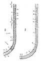
- FIG. 1 represents a production well 1 in which it is desired to carry out measurements of characteristics of fluid flow linked to the formation along the part of the well in production, these measurements having to account for variation of certain characteristics between different points of the production area of the well 1.
- This well comprises a substantially vertical part not shown and a part 3, substantially horizontal or inclined relative to the vertical, in which oil production is carried out in normal operation.
- This production zone comprises a tube 4 perforated over at least part of its length. It is through the perforations that the flow of fluid from the geological formation takes place during activation.
- the present invention proposes to obtain information on these flows and this in a differentiated manner for several locations of the production part of the well.
- Such information may be the flow rate, or the composition of the mixture produced.
- the present invention can in particular make it possible to know the flow rate as a function of the curvilinear abscissa along the production drain. Thus, for example, it is possible to determine the portions of the drain for which water is mainly produced and to intervene on these portions.
- Reference 6 designates the casing of the well in the non-production area and reference 7 designates the shoe at the end of the casing.
- a casing 8 is lowered into the well comprising a means of activating the production comprising a pump 9 and measuring equipment 10.
- the reference 12 designates the annular part between the tube 4 and the casing 8. It is in this zone that the protectors 11 are located.
- the tube 4 can be cemented (as shown in Figure 1) or not (see Figure 2).
- the pump 9 is activated by an electric motor which is integrated into it.
- This motor is powered by an electric cable 14 located in the annular zone 12, as well as in the annular zone 13 located between the casing and the casing 6 over the entire length of the casing.
- This arrangement allows the electrical connection between the motor and the cable to be made on the surface.
- the electric cable 14 is unwound on the surface as the elements constituting the casing 8 are assembled. This assembly is accompanied by an increasing penetration of the motor-pump assembly into the well.
- the casing 8 is sealed over its current length relative to the annular space 12.
- the fluid which enters the casing is that which has been treated by the pump 9.
- the intermediate zone 15 of the casing situated between the pump 9 and the measuring equipment 10 has openings 16.
- the measuring equipment 10 is traversed by the flow of fluids coming from upstream from the well, considering the direction of flow of the fluid coming from the upstream part 18 and going towards the inlet of the pump 9.
- the measuring equipment 10 can include a flow channel within it.
- the pump 9 when it is desired to carry out measurements such as flow measurements, the pump 9 is activated by supplying it with electricity by the cable 14.
- the well is activated and the pump delivers fluid from the downstream part 17 and the upstream part 18 considered in the direction of flow relative to the measuring means 10.
- the fluid coming from the downstream part 17 reaches the pump through openings 16 and the fluid coming from the upstream part 18 passes through the measuring equipment 10. Due to the existence of the openings 16, the measuring equipment 10 appreciably treats only the fraction of the effluent coming from the upstream part of the production drain. Thus, a selective measurement is obtained. It then suffices to move the pump and measuring equipment assembly by adding or removing a certain number of elements from the casing to achieve a new measurement location and perform measurements.
- FIG. 2 represents a variant of the embodiment of FIG. 1.
- the motor and pump assembly is supplied with energy by a cable 19 which runs inside the casing 20 and is connected to the motor by a bottom connector 21.
- the reference 22 designates a connector with side entry allowing the passage of the cable 19 in the annular space 23 of the well. This solution makes it possible to reduce and in certain cases to eliminate the routing of the cable in the annular space of the deviated or horizontal part of the well.
- the establishment of the cable 19 and its connection to the bottom connector is done in a conventional manner.
- a transmission of the data for example digital data obtained by the measuring equipment could be conceived using the power conductor (s) contained in the cables 9 or 19.
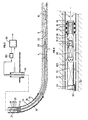
- FIG. 3 represents an embodiment according to which the activation pump is driven by a hydraulic fluid motor, such as a so-called “sparrow” type hydraulic lobe motor.
- a casing 24 is lowered into the well.
- This tubing has two parts.
- the first part 25 of the casing is separated from the second part of the casing 26 by a sealed element 27 such as a flange.
- annular space 29 between the second part 26 of the casing and the secondary casing communicates with the discharge orifices 30 of the pump 9. Furthermore, this annular space 29 communicates with the annular space 34 between the first part of the casing and the casing by means of openings 31 made in the vicinity of the upper end of the second part 26 of the casing above the sealed element 27.
- the reference 32 designates sealing means such as cups. These cups seal between the casing 33 and the casing 24.
- annular space between the casing 33 and the casing 24 is divided into two.
- the cups 32 are located below the openings 31.
- the upper annular space 34 located between the casing 24 and the casing 33 communicates through the openings 31 with the annular space 29 located between the secondary casing 28 and the internal wall of the second part 26 of the casing 24.
- the lower annular space 35 is delimited by the casing 33, the cups 32 and the external wall of the second part 26 of the casing 24.
- the working fluid which feeds the hydraulic motor is transferred from the surface pumps 100 through the first part 25 of the casing 24, through the secondary casing, into the hydraulic motor which drives the pump 9 and is then discharged, at the same time as the fluid pumped from the drain, through the discharge orifices 30 towards the annular space 29, it passes through the openings 31 to join the upper annular space 34 and then join the surface where it can be treated by equipment 110.
- the sealed cups 32 prevent it from joining the lower annular space 35.
- the measurements made at the bottom of the well could be transmitted to the surface using pressure pulses in the circuit of the pump's working fluid (type MWD mud wave transmission).
- Reliability of production measurements and calibration sensors could be increased by simultaneously carrying out identical measurements on the part of the flow coming from upstream and that coming from downstream of the production drain relative to the direction of flow.
- FIG. 4 represents an embodiment allowing in particular these measurements.
- the reference 36 designates the geological formation, the reference 37 the tube comprising perforations, the reference 38 the sealing cups. These cups make it possible to isolate the upstream part well from the flow of the downstream part.
- the reference 39 designates the measurement equipment which operates on the upstream flow, these means correspond substantially in their function to those shown in FIGS. 1, 2 and 3.
- the reference 40 designates measuring equipment which operates on the downstream flow.
- the downstream flow comes to these devices 40 through the channel 41 which communicates with the annular space 420.
- the channel 41 does not communicate with the upstream fluid having passed through the first measuring equipment 39 or upstream measuring equipment.
- the fluid coming from these upstream measuring equipment is mixed with the fluid coming from the downstream part of the drain only after this downstream fluid has passed through the downstream measuring equipment 40.
- the pump 42 delivers all of the upstream and downstream fluid.
- FIG. 4 shows a pump actuated by an electric motor powered by the cable 43.
- the measurement equipment 39 and 40 can be connected by electrical wires, not shown, to an electronic unit 44 used to process these different signals in order to transfer them to the surface by the electric cable 43 which may include one or more electrical connections.
- the entire production from the well passes through the upstream measuring device, the cups 2 preventing the fluid from flowing according to another circuit.
- the zone 45A even if it is not cemented forms a dead end for the fluid.
- Calibration can be easily performed by comparison with wellhead measurements. Several measurement points can be obtained by varying the pump flow. If necessary, the downstream measuring device can be calibrated by imposing a circulation on the well head via the annular of the casing which can have a diameter of 24.5 cm (9. "5/8).
- this device also has the advantage on the one hand of a concentration of the flow allowing a dispersed flow and a greater precision of the measurement, on the other hand eliminates any risk of circulation against the current in the well (only the flow rates at the intake of the pump are counted).
- references 45 and 46 designate absolute, relative or differential pressure sensors which are connected to the electronic unit by lines 47.
- a device making it possible to vary the pressure drops in one of the two sets of measurements or less makes it possible to minimize the error due to the leakage rate by adjusting the differential pressure to zero.
- Such a device can be adjusted by a command from the electronic unit 44 or can be autonomous.
- the characteristics of the leak behind the perforated tube could be assessed as follows: - positioning of the assembly in the drain. - pump flow Q T - measurement of the upstream and downstream flows and of the pressure after adjusting the device mentioned above to adjust the differential pressure to a zero value.
- Q T Q av + Q am - complete closure of the downstream flow meter.
- the downstream measurement means 40 comprise a remote-controlled obstruction means.
- New flow Q ′ T Q ′ am .
- a sand trap 49 interposed between the strainer 50 and the impact detector makes it possible, on the one hand, to obtain a sand sampling, on the other hand, to provide a semi quantitative indication on the measurements obtained by the detector d impact, by comparing the quantity of sand to the sum of the impact count recorded.
- the sand trap consists in particular of a sand circulation circuit having a baffle shape upstream of the strainer 50.
- FIGS. 7 and 8 show an example of the conclusions which the device and the method according to the present invention make it possible to obtain.
- the abscissa x represents the curvilinear abscissa along the production part of the drain.
- the ordinate of FIG. 7 represents the counts c carried out by the impact detector.
- Curve 51 represents the number of impacts (as a function of the curvilinear abscissa x. Between X1 and X2 this number is high. The integral of this curve is related substantially to the total amount of sand drained and can therefore be compared to the amount of sand collected in the sand trap 49.
- FIG. 8 the abscissa axis of which is calibrated on that of FIG. 7, represents on the ordinate a quantity Q proportional to the quantity of water collected.
- This quantity can be for example the water-cut ratio which corresponds to the quantity of water produced compared to the total quantity of liquid produced (water + oil). More simply, this quantity can be equal to the flow of water produced.
- the production operator can decide to stop the production of the drain on the portion between x1 and x2 and thus increase the quality of the production of his well.
Landscapes
- Geology (AREA)
- Life Sciences & Earth Sciences (AREA)
- Engineering & Computer Science (AREA)
- Mining & Mineral Resources (AREA)
- Physics & Mathematics (AREA)
- Environmental & Geological Engineering (AREA)
- Fluid Mechanics (AREA)
- General Life Sciences & Earth Sciences (AREA)
- Geochemistry & Mineralogy (AREA)
- Geophysics (AREA)
- Measuring Volume Flow (AREA)
- Pharmaceuticals Containing Other Organic And Inorganic Compounds (AREA)
- General Factory Administration (AREA)
Applications Claiming Priority (4)
| Application Number | Priority Date | Filing Date | Title |
|---|---|---|---|
| FR8813605A FR2637939B1 (fr) | 1988-10-14 | 1988-10-14 | Procede et dispositif de diagraphie en puits de production non eruptif |
| FR8813605 | 1988-10-14 | ||
| FR8904225 | 1989-03-29 | ||
| FR8904225 | 1989-03-29 |
Publications (2)
| Publication Number | Publication Date |
|---|---|
| EP0364362A1 true EP0364362A1 (de) | 1990-04-18 |
| EP0364362B1 EP0364362B1 (de) | 1992-07-08 |
Family
ID=26226934
Family Applications (1)
| Application Number | Title | Priority Date | Filing Date |
|---|---|---|---|
| EP89402813A Expired - Lifetime EP0364362B1 (de) | 1988-10-14 | 1989-10-12 | Verfahren und Vorrichtung zum Messen in einem nichteruptiven Bohrloch |
Country Status (5)
| Country | Link |
|---|---|
| US (1) | US5042297A (de) |
| EP (1) | EP0364362B1 (de) |
| CA (1) | CA2000665C (de) |
| DK (1) | DK506389A (de) |
| NO (1) | NO178083C (de) |
Cited By (3)
| Publication number | Priority date | Publication date | Assignee | Title |
|---|---|---|---|---|
| EP0484207A1 (de) * | 1990-11-02 | 1992-05-06 | Institut Francais Du Petrole | Verfahren zum Befördern der Produktion einer Flüssigkeit in einer Produktionszone |
| WO1992008875A3 (en) * | 1990-11-20 | 1992-07-09 | Framo Dev Ltd | Well completion system |
| EP0417369B1 (de) * | 1989-09-14 | 1994-03-30 | Societe De Prospection Electrique Schlumberger | Verfahren und Vorrichtung zur Messung im Bohrloch unterhalb einer Pumpe |
Families Citing this family (41)
| Publication number | Priority date | Publication date | Assignee | Title |
|---|---|---|---|---|
| US5163515A (en) * | 1991-04-23 | 1992-11-17 | Den Norske Stats Oljeselskap A.S | Pumpdown toolstring operations in horizontal or high-deviation oil or gas wells |
| FR2677701B1 (fr) * | 1991-06-11 | 1993-09-03 | Inst Francais Du Petrole | Methode pour poursuivre des mesures apres la recuperation d'un outil de mesure immobilise dans un puits. |
| US5284208A (en) * | 1992-10-15 | 1994-02-08 | Halliburton Company | Production logging system using through flow line tools |
| FR2683590B1 (fr) * | 1991-11-13 | 1993-12-31 | Institut Francais Petrole | Dispositif de mesure et d'intervention dans un forage, procede d'assemblage et utilisation dans un puits petrolier. |
| US5477923A (en) * | 1992-08-07 | 1995-12-26 | Baker Hughes Incorporated | Wellbore completion using measurement-while-drilling techniques |
| US5452761A (en) * | 1994-10-31 | 1995-09-26 | Western Atlas International, Inc. | Synchronized digital stacking method and application to induction logging tools |
| US6101871A (en) * | 1995-02-28 | 2000-08-15 | Sandra K. Myers | In-ground vapor monitoring device and method |
| US5884701A (en) * | 1997-07-18 | 1999-03-23 | Schlumberger Technology Corpporation | Dual downhole injection system utilizing coiled tubing |
| FR2776769B1 (fr) * | 1998-03-30 | 2000-04-28 | Schlumberger Services Petrol | Procede et installation de mise en oeuvre d'un debitmetre multiphasique, en aval d'un puits de petrole |
| US7513305B2 (en) * | 1999-01-04 | 2009-04-07 | Weatherford/Lamb, Inc. | Apparatus and methods for operating a tool in a wellbore |
| US7185700B2 (en) * | 2004-06-14 | 2007-03-06 | Weatherford/Lamb, Inc. | Separable plug for use with a wellbore tool |
| US7407006B2 (en) * | 1999-01-04 | 2008-08-05 | Weatherford/Lamb, Inc. | System for logging formations surrounding a wellbore |
| US6279660B1 (en) * | 1999-08-05 | 2001-08-28 | Cidra Corporation | Apparatus for optimizing production of multi-phase fluid |
| GB2363809B (en) * | 2000-06-21 | 2003-04-02 | Schlumberger Holdings | Chemical sensor for wellbore applications |
| WO2002086287A2 (en) * | 2001-04-23 | 2002-10-31 | Weatherford/Lamb, Inc. | Conveying instrumentation within a borehole |
| US7155967B2 (en) * | 2002-07-09 | 2007-01-02 | Schlumberger Technology Corporation | Formation testing apparatus and method |
| US7350569B2 (en) * | 2004-06-14 | 2008-04-01 | Weatherford/Lamb, Inc. | Separable plug for use in a wellbore |
| EA014072B1 (ru) * | 2005-09-30 | 2010-08-30 | Эксонмобил Апстрим Рисерч Компани | Скважинное устройство и способ завершения скважины, добычи и нагнетания |
| US9982519B2 (en) | 2014-07-14 | 2018-05-29 | Saudi Arabian Oil Company | Flow meter well tool |
| AU2017246520B2 (en) | 2016-04-07 | 2022-04-07 | Bp Exploration Operating Company Limited | Detecting downhole events using acoustic frequency domain features |
| BR112018070565A2 (pt) | 2016-04-07 | 2019-02-12 | Bp Exploration Operating Company Limited | detecção de eventos de fundo de poço usando características de domínio da frequência acústicas |
| EP3608503B1 (de) | 2017-03-31 | 2022-05-04 | BP Exploration Operating Company Limited | Bohrloch- und abraumüberwachung mithilfe verteilter akustiksensoren |
| CN107044273B (zh) | 2017-04-07 | 2018-06-22 | 中国石油大学(华东) | 防砂井筒堵塞-解堵一体化评价实验模拟装置及方法 |
| BR112020003742A2 (pt) | 2017-08-23 | 2020-09-01 | Bp Exploration Operating Company Limited | detecção de localizações de ingresso de areia em fundo de poço |
| CA3078842C (en) | 2017-10-11 | 2024-01-09 | Bp Exploration Operating Company Limited | Detecting events using acoustic frequency domain features |
| US10982515B2 (en) * | 2018-05-23 | 2021-04-20 | Intrinsic Energy Technology, LLC | Electric submersible hydraulic lift pump system |
| US20200174149A1 (en) | 2018-11-29 | 2020-06-04 | Bp Exploration Operating Company Limited | Event Detection Using DAS Features with Machine Learning |
| GB201820331D0 (en) | 2018-12-13 | 2019-01-30 | Bp Exploration Operating Co Ltd | Distributed acoustic sensing autocalibration |
| US10920586B2 (en) | 2018-12-28 | 2021-02-16 | Saudi Arabian Oil Company | Systems and methods for logging while treating |
| WO2021052602A1 (en) | 2019-09-20 | 2021-03-25 | Lytt Limited | Systems and methods for sand ingress prediction for subterranean wellbores |
| EP4045766A1 (de) | 2019-10-17 | 2022-08-24 | Lytt Limited | Flüssigkeitszuflusscharakterisierung unter verwendung von hybriden das/dts-messungen |
| CA3154435C (en) | 2019-10-17 | 2023-03-28 | Lytt Limited | Inflow detection using dts features |
| WO2021093974A1 (en) | 2019-11-15 | 2021-05-20 | Lytt Limited | Systems and methods for draw down improvements across wellbores |
| US11255160B2 (en) | 2019-12-09 | 2022-02-22 | Saudi Arabian Oil Company | Unblocking wellbores |
| WO2021249643A1 (en) | 2020-06-11 | 2021-12-16 | Lytt Limited | Systems and methods for subterranean fluid flow characterization |
| WO2021254633A1 (en) | 2020-06-18 | 2021-12-23 | Lytt Limited | Event model training using in situ data |
| CA3182376A1 (en) | 2020-06-18 | 2021-12-23 | Cagri CERRAHOGLU | Event model training using in situ data |
| US11352867B2 (en) | 2020-08-26 | 2022-06-07 | Saudi Arabian Oil Company | Enhanced hydrocarbon recovery with electric current |
| US11608723B2 (en) | 2021-01-04 | 2023-03-21 | Saudi Arabian Oil Company | Stimulated water injection processes for injectivity improvement |
| US11421148B1 (en) | 2021-05-04 | 2022-08-23 | Saudi Arabian Oil Company | Injection of tailored water chemistry to mitigate foaming agents retention on reservoir formation surface |
| US11993746B2 (en) | 2022-09-29 | 2024-05-28 | Saudi Arabian Oil Company | Method of waterflooding using injection solutions containing dihydrogen phosphate |
Citations (9)
| Publication number | Priority date | Publication date | Assignee | Title |
|---|---|---|---|---|
| US2688872A (en) * | 1949-06-08 | 1954-09-14 | Stanolind Oil & Gas Co | Apparatus for fluid entry logging |
| US3059695A (en) * | 1960-03-07 | 1962-10-23 | Jersey Prod Res Co | Drill stem testing device |
| FR1322402A (fr) * | 1962-03-20 | 1963-03-29 | Petroleum Res Corp | Système d'analyse de couches de terrains multiples |
| US3123708A (en) * | 1964-03-03 | Well production method using radioactive | ||
| US3283570A (en) * | 1963-06-26 | 1966-11-08 | Sun Oil Co | Production measurement in multiple completion wells |
| US4006630A (en) * | 1976-05-26 | 1977-02-08 | Atlantic Richfield Company | Well testing apparatus |
| US4222438A (en) * | 1978-10-30 | 1980-09-16 | Standard Oil Company (Indiana) | Reservoir fluid sampling method and apparatus |
| FR2519689A1 (fr) * | 1982-01-12 | 1983-07-18 | Elf Aquitaine | Installation pour la mise en essai d'un puits au moyen d'une pompe immergee et procede pour sa mise en oeuvre |
| US4453599A (en) * | 1982-05-10 | 1984-06-12 | Otis Engineering Corporation | Method and apparatus for controlling a well |
Family Cites Families (3)
| Publication number | Priority date | Publication date | Assignee | Title |
|---|---|---|---|---|
| US2379138A (en) * | 1943-01-11 | 1945-06-26 | Shell Dev | Annular flow measuring device |
| SU691723A1 (ru) * | 1977-07-20 | 1979-10-15 | Северо-Кавказский Государственный Научно-Исследовательский И Проектный Институт Нефтяной Промышленности | Устройство дл отбора проб жидкости |
| SU1244162A1 (ru) * | 1984-06-22 | 1986-07-15 | Азербайджанский Институт Нефти И Химии Им.М.Азизбекова | Способ поинтервального измерени в зкости бурового раствора |
-
1989
- 1989-10-12 NO NO894084A patent/NO178083C/no not_active IP Right Cessation
- 1989-10-12 EP EP89402813A patent/EP0364362B1/de not_active Expired - Lifetime
- 1989-10-12 DK DK506389A patent/DK506389A/da not_active Application Discontinuation
- 1989-10-13 CA CA002000665A patent/CA2000665C/fr not_active Expired - Fee Related
- 1989-10-16 US US07/422,105 patent/US5042297A/en not_active Expired - Lifetime
Patent Citations (9)
| Publication number | Priority date | Publication date | Assignee | Title |
|---|---|---|---|---|
| US3123708A (en) * | 1964-03-03 | Well production method using radioactive | ||
| US2688872A (en) * | 1949-06-08 | 1954-09-14 | Stanolind Oil & Gas Co | Apparatus for fluid entry logging |
| US3059695A (en) * | 1960-03-07 | 1962-10-23 | Jersey Prod Res Co | Drill stem testing device |
| FR1322402A (fr) * | 1962-03-20 | 1963-03-29 | Petroleum Res Corp | Système d'analyse de couches de terrains multiples |
| US3283570A (en) * | 1963-06-26 | 1966-11-08 | Sun Oil Co | Production measurement in multiple completion wells |
| US4006630A (en) * | 1976-05-26 | 1977-02-08 | Atlantic Richfield Company | Well testing apparatus |
| US4222438A (en) * | 1978-10-30 | 1980-09-16 | Standard Oil Company (Indiana) | Reservoir fluid sampling method and apparatus |
| FR2519689A1 (fr) * | 1982-01-12 | 1983-07-18 | Elf Aquitaine | Installation pour la mise en essai d'un puits au moyen d'une pompe immergee et procede pour sa mise en oeuvre |
| US4453599A (en) * | 1982-05-10 | 1984-06-12 | Otis Engineering Corporation | Method and apparatus for controlling a well |
Non-Patent Citations (1)
| Title |
|---|
| SPE DRILLING ENGINEERING, juin 1987, pages 127-135, Society of Petroleum Engineers, Richardson, Texas, US; P. DeGAUQUE et al.: "Propagation of electromagnetic waves along a drillstring of finite conductivity" * |
Cited By (4)
| Publication number | Priority date | Publication date | Assignee | Title |
|---|---|---|---|---|
| EP0417369B1 (de) * | 1989-09-14 | 1994-03-30 | Societe De Prospection Electrique Schlumberger | Verfahren und Vorrichtung zur Messung im Bohrloch unterhalb einer Pumpe |
| EP0484207A1 (de) * | 1990-11-02 | 1992-05-06 | Institut Francais Du Petrole | Verfahren zum Befördern der Produktion einer Flüssigkeit in einer Produktionszone |
| FR2668795A1 (fr) * | 1990-11-02 | 1992-05-07 | Inst Francais Du Petrole | Methode pour favoriser la production d'effluents d'une zone de production. |
| WO1992008875A3 (en) * | 1990-11-20 | 1992-07-09 | Framo Dev Ltd | Well completion system |
Also Published As
| Publication number | Publication date |
|---|---|
| CA2000665C (fr) | 1999-12-28 |
| DK506389D0 (da) | 1989-10-12 |
| NO178083B (no) | 1995-10-09 |
| EP0364362B1 (de) | 1992-07-08 |
| US5042297A (en) | 1991-08-27 |
| NO894084D0 (no) | 1989-10-12 |
| DK506389A (da) | 1990-04-15 |
| NO894084L (no) | 1990-04-17 |
| CA2000665A1 (fr) | 1990-04-14 |
| NO178083C (no) | 1996-01-17 |
Similar Documents
| Publication | Publication Date | Title |
|---|---|---|
| EP0364362B1 (de) | Verfahren und Vorrichtung zum Messen in einem nichteruptiven Bohrloch | |
| EP0251881B1 (de) | Gewinnungsverfahren für eine in einer geologischen Formation enthaltene zu produzierende Flüssigkeit | |
| US8622128B2 (en) | In-situ evaluation of reservoir sanding and fines migration and related completion, lift and surface facilities design | |
| US7836973B2 (en) | Annulus pressure control drilling systems and methods | |
| FR2751373A1 (fr) | Perfectionnement aux appareils de circulation de fluide | |
| FR2910922A1 (fr) | Controle de pompe pour essai de couches | |
| FR2885166A1 (fr) | Methode et appareil d'analyse des fluides | |
| OA10434A (fr) | Procédé et installation de pompage d'un effluent pétrolier | |
| EP1322837B1 (de) | Testsystem für öl- oder gasquellen | |
| FR2861797A1 (fr) | Systeme de liaison descendante pour forage et procede de production d'un signal utilisant un controleur de l'inefficacite d'une pompe | |
| FR2911630A1 (fr) | Outil de fond a sonde d'echantillonnage | |
| EP0435727B1 (de) | Verfahren und Vorrichtung zur Stimulation einer Untergrundformation durch Injektion eines Fluids aus einer benachbarten Schicht, die durch eine eine niedrigpermeable Zwischenschicht durchquerende Bohrung mit ersterer verbunden ist | |
| FR2619155A1 (fr) | Procede d'analyse dynamique des venues de fluides dans les puits d'hydrocarbures | |
| FR3086779A1 (fr) | Mise en correspondance avec un historique de production automatisée à l’aide de l’optimisation bayésienne | |
| US6164127A (en) | Well flowmeter and down-hole sampler | |
| CA1124102A (fr) | Dispositif permettant la mesure simultanee des parametres relatifs au fluide de forage | |
| FR3061235B1 (fr) | Outil de fond de puits a dispositif de filtration | |
| FR2706526A1 (fr) | Procédé et système de détection précoce du bourrage d'un dispositif de prélèvement d'échantillons de carotte dans un trou de forage et de prise de mesures palliatives. | |
| FR2637939A1 (fr) | Procede et dispositif de diagraphie en puits de production non eruptif | |
| EP0461963B1 (de) | Verfahren und Vorrichtung zum Messen in einem Nicht-eruptiven Bohrloch | |
| WO2000039431A1 (fr) | Procede et dispositif pour regler a une valeur de consigne le niveau du fluide de forage dans le tube prolongateur | |
| CA2012772C (fr) | Methode et dispositif de diagraphie de production en puits eruptif | |
| CA2045927C (fr) | Dispositif perfectionne d'activation et de mesure pour puits non eruptifs en cours de production | |
| EP0231708B1 (de) | Vorrichtung und Verfahren zur Bestimmung der Orientierung von Spalten in einer geologischen Formation | |
| CA2971753A1 (fr) | Dispositif d'evacuation de liquides accumules dans un puits |
Legal Events
| Date | Code | Title | Description |
|---|---|---|---|
| PUAI | Public reference made under article 153(3) epc to a published international application that has entered the european phase |
Free format text: ORIGINAL CODE: 0009012 |
|
| 17P | Request for examination filed |
Effective date: 19891021 |
|
| AK | Designated contracting states |
Kind code of ref document: A1 Designated state(s): FR GB IT NL |
|
| 17Q | First examination report despatched |
Effective date: 19910425 |
|
| ITF | It: translation for a ep patent filed | ||
| GRAA | (expected) grant |
Free format text: ORIGINAL CODE: 0009210 |
|
| AK | Designated contracting states |
Kind code of ref document: B1 Designated state(s): FR GB IT NL |
|
| GBT | Gb: translation of ep patent filed (gb section 77(6)(a)/1977) | ||
| PLBE | No opposition filed within time limit |
Free format text: ORIGINAL CODE: 0009261 |
|
| STAA | Information on the status of an ep patent application or granted ep patent |
Free format text: STATUS: NO OPPOSITION FILED WITHIN TIME LIMIT |
|
| 26N | No opposition filed | ||
| REG | Reference to a national code |
Ref country code: GB Ref legal event code: IF02 |
|
| PGFP | Annual fee paid to national office [announced via postgrant information from national office to epo] |
Ref country code: GB Payment date: 20031006 Year of fee payment: 15 |
|
| PGFP | Annual fee paid to national office [announced via postgrant information from national office to epo] |
Ref country code: FR Payment date: 20031015 Year of fee payment: 15 |
|
| PGFP | Annual fee paid to national office [announced via postgrant information from national office to epo] |
Ref country code: NL Payment date: 20031031 Year of fee payment: 15 |
|
| PG25 | Lapsed in a contracting state [announced via postgrant information from national office to epo] |
Ref country code: GB Free format text: LAPSE BECAUSE OF NON-PAYMENT OF DUE FEES Effective date: 20041012 |
|
| PG25 | Lapsed in a contracting state [announced via postgrant information from national office to epo] |
Ref country code: NL Free format text: LAPSE BECAUSE OF NON-PAYMENT OF DUE FEES Effective date: 20050501 |
|
| GBPC | Gb: european patent ceased through non-payment of renewal fee |
Effective date: 20041012 |
|
| PG25 | Lapsed in a contracting state [announced via postgrant information from national office to epo] |
Ref country code: FR Free format text: LAPSE BECAUSE OF NON-PAYMENT OF DUE FEES Effective date: 20050630 |
|
| NLV4 | Nl: lapsed or anulled due to non-payment of the annual fee |
Effective date: 20050501 |
|
| REG | Reference to a national code |
Ref country code: FR Ref legal event code: ST |
|
| PG25 | Lapsed in a contracting state [announced via postgrant information from national office to epo] |
Ref country code: IT Free format text: LAPSE BECAUSE OF NON-PAYMENT OF DUE FEES;WARNING: LAPSES OF ITALIAN PATENTS WITH EFFECTIVE DATE BEFORE 2007 MAY HAVE OCCURRED AT ANY TIME BEFORE 2007. THE CORRECT EFFECTIVE DATE MAY BE DIFFERENT FROM THE ONE RECORDED. Effective date: 20051012 |