EP0364574B1 - Generateur de micro-ondes de haute puissance assiste par plasma - Google Patents
Generateur de micro-ondes de haute puissance assiste par plasma Download PDFInfo
- Publication number
- EP0364574B1 EP0364574B1 EP89907396A EP89907396A EP0364574B1 EP 0364574 B1 EP0364574 B1 EP 0364574B1 EP 89907396 A EP89907396 A EP 89907396A EP 89907396 A EP89907396 A EP 89907396A EP 0364574 B1 EP0364574 B1 EP 0364574B1
- Authority
- EP
- European Patent Office
- Prior art keywords
- plasma
- cathode
- electron
- electron gun
- oscillator
- Prior art date
- Legal status (The legal status is an assumption and is not a legal conclusion. Google has not performed a legal analysis and makes no representation as to the accuracy of the status listed.)
- Expired - Lifetime
Links
- 238000010894 electron beam technology Methods 0.000 claims abstract description 29
- 239000007789 gas Substances 0.000 claims description 47
- 229910052751 metal Inorganic materials 0.000 claims description 9
- 239000002184 metal Substances 0.000 claims description 9
- 230000015556 catabolic process Effects 0.000 claims description 8
- 239000001307 helium Substances 0.000 claims description 7
- 229910052734 helium Inorganic materials 0.000 claims description 7
- SWQJXJOGLNCZEY-UHFFFAOYSA-N helium atom Chemical compound [He] SWQJXJOGLNCZEY-UHFFFAOYSA-N 0.000 claims description 7
- 150000002500 ions Chemical class 0.000 claims description 7
- 230000005670 electromagnetic radiation Effects 0.000 claims description 6
- QVGXLLKOCUKJST-UHFFFAOYSA-N atomic oxygen Chemical compound [O] QVGXLLKOCUKJST-UHFFFAOYSA-N 0.000 claims description 4
- 239000001301 oxygen Substances 0.000 claims description 4
- 229910052760 oxygen Inorganic materials 0.000 claims description 4
- 230000002708 enhancing effect Effects 0.000 claims description 2
- 230000005855 radiation Effects 0.000 abstract description 10
- 238000000605 extraction Methods 0.000 abstract description 2
- 229910044991 metal oxide Inorganic materials 0.000 abstract description 2
- 150000004706 metal oxides Chemical class 0.000 abstract 1
- 230000008878 coupling Effects 0.000 description 10
- 238000010168 coupling process Methods 0.000 description 10
- 238000005859 coupling reaction Methods 0.000 description 10
- 230000000694 effects Effects 0.000 description 5
- 230000001965 increasing effect Effects 0.000 description 5
- 238000013459 approach Methods 0.000 description 3
- 230000003993 interaction Effects 0.000 description 3
- 230000007246 mechanism Effects 0.000 description 3
- 230000004044 response Effects 0.000 description 3
- UFHFLCQGNIYNRP-UHFFFAOYSA-N Hydrogen Chemical compound [H][H] UFHFLCQGNIYNRP-UHFFFAOYSA-N 0.000 description 2
- 238000010276 construction Methods 0.000 description 2
- 230000005284 excitation Effects 0.000 description 2
- 239000011888 foil Substances 0.000 description 2
- 239000003574 free electron Substances 0.000 description 2
- 239000001257 hydrogen Substances 0.000 description 2
- 229910052739 hydrogen Inorganic materials 0.000 description 2
- 230000000737 periodic effect Effects 0.000 description 2
- 230000009467 reduction Effects 0.000 description 2
- 230000002195 synergetic effect Effects 0.000 description 2
- VYZAMTAEIAYCRO-UHFFFAOYSA-N Chromium Chemical compound [Cr] VYZAMTAEIAYCRO-UHFFFAOYSA-N 0.000 description 1
- FYYHWMGAXLPEAU-UHFFFAOYSA-N Magnesium Chemical compound [Mg] FYYHWMGAXLPEAU-UHFFFAOYSA-N 0.000 description 1
- ZOKXTWBITQBERF-UHFFFAOYSA-N Molybdenum Chemical compound [Mo] ZOKXTWBITQBERF-UHFFFAOYSA-N 0.000 description 1
- 229910052782 aluminium Inorganic materials 0.000 description 1
- XAGFODPZIPBFFR-UHFFFAOYSA-N aluminium Chemical compound [Al] XAGFODPZIPBFFR-UHFFFAOYSA-N 0.000 description 1
- 229910052790 beryllium Inorganic materials 0.000 description 1
- ATBAMAFKBVZNFJ-UHFFFAOYSA-N beryllium atom Chemical compound [Be] ATBAMAFKBVZNFJ-UHFFFAOYSA-N 0.000 description 1
- 239000010406 cathode material Substances 0.000 description 1
- 229910052804 chromium Inorganic materials 0.000 description 1
- 239000011651 chromium Substances 0.000 description 1
- 239000011248 coating agent Substances 0.000 description 1
- 238000000576 coating method Methods 0.000 description 1
- 238000011109 contamination Methods 0.000 description 1
- PTVDYARBVCBHSL-UHFFFAOYSA-N copper;hydrate Chemical compound O.[Cu] PTVDYARBVCBHSL-UHFFFAOYSA-N 0.000 description 1
- 230000001808 coupling effect Effects 0.000 description 1
- 238000011161 development Methods 0.000 description 1
- 230000018109 developmental process Effects 0.000 description 1
- 238000010586 diagram Methods 0.000 description 1
- 230000005684 electric field Effects 0.000 description 1
- 238000000609 electron-beam lithography Methods 0.000 description 1
- 238000005516 engineering process Methods 0.000 description 1
- 239000000945 filler Substances 0.000 description 1
- 230000001939 inductive effect Effects 0.000 description 1
- 229910052749 magnesium Inorganic materials 0.000 description 1
- 239000011777 magnesium Substances 0.000 description 1
- 238000004519 manufacturing process Methods 0.000 description 1
- 239000000463 material Substances 0.000 description 1
- 238000000034 method Methods 0.000 description 1
- 229910052750 molybdenum Inorganic materials 0.000 description 1
- 239000011733 molybdenum Substances 0.000 description 1
- 229910052754 neon Inorganic materials 0.000 description 1
- GKAOGPIIYCISHV-UHFFFAOYSA-N neon atom Chemical compound [Ne] GKAOGPIIYCISHV-UHFFFAOYSA-N 0.000 description 1
- 230000003287 optical effect Effects 0.000 description 1
- 230000010355 oscillation Effects 0.000 description 1
- 239000002574 poison Substances 0.000 description 1
- 231100000614 poison Toxicity 0.000 description 1
- 230000001902 propagating effect Effects 0.000 description 1
- 238000011084 recovery Methods 0.000 description 1
- 238000011160 research Methods 0.000 description 1
- 238000012552 review Methods 0.000 description 1
- 238000001894 space-charge-limited current method Methods 0.000 description 1
- 238000001228 spectrum Methods 0.000 description 1
- 229910001220 stainless steel Inorganic materials 0.000 description 1
- 239000010935 stainless steel Substances 0.000 description 1
- 238000012546 transfer Methods 0.000 description 1
- 230000025594 tube development Effects 0.000 description 1
- WFKWXMTUELFFGS-UHFFFAOYSA-N tungsten Chemical compound [W] WFKWXMTUELFFGS-UHFFFAOYSA-N 0.000 description 1
- 229910052721 tungsten Inorganic materials 0.000 description 1
- 239000010937 tungsten Substances 0.000 description 1
- 229910000568 zirconium hydride Inorganic materials 0.000 description 1
Images


Classifications
-
- H—ELECTRICITY
- H01—ELECTRIC ELEMENTS
- H01J—ELECTRIC DISCHARGE TUBES OR DISCHARGE LAMPS
- H01J25/00—Transit-time tubes, e.g. klystrons, travelling-wave tubes, magnetrons
- H01J25/005—Gas-filled transit-time tubes
Definitions
- This invention relates to a high current electron gun and an oscillator including such a high current electron gun, and in particular relates to high-power microwave/mm-wave generators, and more-particularly to oscillators which operate by coupling an electron beam to a slow electromagnetic wave in a plasma-loaded, rippled-wall waveguide.
- an electronic discharge tube comprising means for forming a periodic, non-homogeneous structure in the plasma column, through the use of appropriate voltages, or a magnetic field of an intensity varying periodically along the axis of the envelope containing the gas and being surrounded by a wall which forms a waveguide.
- an electron beam plasma amplifier with a wave-guide coupling comprising an envelope containing an ionizable gas medium, means within said envelope for generating an electron beam, means for generating a plasma, and input and output couplers wherein at least one of the signal couplers is located in the range of the plasma while the coupler is constructed in the form of a coupler suitable for use in a waveguide system. At least one of the signal couplers is located in the interaction space of the electron beam and the plasma.
- the approach generally is to couple an electron beam with an evacuated waveguide structure at a high vacuum, on the order of 10 ⁇ 4 Pa (10 ⁇ 6 Torr) or less.
- a space-charge wave is induced on the electron beam and couples within the waveguide structure to an electromagnetic waveguide mode, and thereby emits microwave or mm-wave energy at the end of the guide.
- the prior devices cannot generate pulse lengths longer than a few hundred nanoseconds because they use field-emitting cathodes in their electron guns; these generate an expanding uncontrolled plasma surface in the evacuated high-voltage-diode electron gun gap.
- the plasma surface propagates from cathode to anode, shorting the gap in 100-1,000 nanoseconds, and thus terminating the pulse.
- Devices such as the vircator also use a metal-foil anode that self-destructs in about 100 nanoseconds.
- the magnetic focusing required to counteract space-charge blowup needs a very strong magnetic field, on the order of 1T (10 kGauss) or more, and associated bulky magnets.
- the axial velocity shear produced by the space-charged fields also reduces the efficiency of the oscillator at high beam current densities.
- Other types of electron guns include plasma anode devices, and wire ion plasma guns.
- the former device is described in U.S. Patent No. 4,707,637 issued November 17, 1987 in the name of Robin J. Harvey, while the latter is described in U.S. Patent No. 4,025,818, issued May 24, 1977 in the name of Robert P. Giguere, both assigned to Hughes Aircraft Company, the assignee of the present invention.
- Another electron gun is described in U.S. Patent No. 3,831,052, issued August 20, 1974 in the name of Ronald C. Knechtli, and also assigned to Hughes Aircraft Company.
- the latter device is a hollow cathode gas discharge mechanism used to produce an electron beam with a rectangular cross-section for driving gas lasers.
- a discharge is struck through a gas within the cathode, between the cathode walls and a rectangular perforated anode which is situated within a cathode exit slit.
- a relative positive polarity is applied to the anode electrode to extract electrons from the plasma.
- the electrons are accelerated by a greater positive polarity on a control grid, and once past the control grid are further accelerated by a high voltage accelerating field between a thin foil window and the grid.
- the purpose of the present invention is to provide an improved microwave/mm-wave oscillator for generating high power radiation, with long pulses of up to 100 microseconds, and to do so with a system that neutralizes electron-beam space-charge blowup without the use of externally applied magnetic fields. Increased efficiency, the avoidance of contamination in the system, an easy mechanism for coupling energy out of the system, an ability to easily adjust the frequency of the generated radiation, and a generally simplified and low cost construction are other advantages sought.
- An improved electron gun for use in the oscillator capable of achieving much greater current densities than previously available, is a further aspect of the invention.
- the invention is defined by a high current electron gun in accordance with claim 1 and by an oscillator including such electron gun in accordance with claim 6.
- the invention accomplishes these goals by injecting a high current density electron beam, up to 100 A/cm2, but at least about 1 amp/cm2, into a waveguide structure having a "soft" vacuum within the approximate range of 0,13-3 Pa (1-20 mTorr) as opposed to the prior "hard” vacuum on the order of 10 ⁇ 4 Pa (10 ⁇ 6 Torr) or less.
- the electron beam current density is high enough to at least partially ionize the gas within the waveguide.
- the gas pressure is kept at a level sufficiently low to avoid voltage breakdown in the electron gun, but sufficiently high to provide enough ions to substantially neutralize space-charge blowup of the beam and to remove the potential depression.
- the oscillator can be implemented as a slow-wave tube, in which the waveguide housing has a rippled wall and single-mode, narrow-band, low-frequency microwave radiation is generated by maintaining the gas pressure within the approximate range of 0,13-0.7 Pa (1-5 mTorr). Broadband, high-frequency, noise-modulated microwave and mm-wave radiation is achieved by maintaining the gas pressure within the approximate range of 1,3-3 Pa (10-20 mTorr).
- a new type of electron gun for achieving the high current density employs a hollow cathode, an apertured grid located adjacent to multiple outlets from the cathode, and means for establishing an electrical glow discharge through a gas between the cathode and the grid to generate a plasma within the cathode.
- the grid has a generally high transparency, but with apertures small enough to prevent the passage of plasma through the grid.
- a generally transparent anode on the opposite side of the grid from the cathode maintains a high positive electric potential to extract an electron beam from the plasma behind the grid.
- the inner cathode surface is formed from a chemically active metal, and the gas is doped with a trace amount of oxygen to form an oxide of the metal, thereby enhancing the secondary electron yield from the cathode and permitting operation in the lower pressure range.
- Beam losses are reduced by providing the cathode, grid and anode with respective sets of apertures that are mutually aligned.
- the grid, anode, and end surface of the cathode are curved concave with respect to the beam to geometrically focus the beam, while the outer surface of the hollow cathode is cylindrical to generate an electron beam with a substantially circular cross-section.
- the microwave/mm-wave oscillator of the present invention uses a "soft", partially gas-filled vacuum tube to generate high-power electromagnetic radiation, as opposed to the prior "hard” (very high vacuum) tubes. It employs the conventional approach of coupling an electron beam space-charge wave to an electromagnetic waveguide mode. However, it significantly simplifies the engineering and manufacturing of a high power oscillator, while simultaneously amplifying its performance by a wide margin. This is accomplished by combining three synergistic plasma-assisted technologies. They include a stabilized plasma-cathode electron gun, beam transport in a low pressure gas by ion focusing and Bennett pinch, and enhanced coupling through refractive effects and collective beam-plasma interaction.
- FIG. 1 A new electron gun configuration is illustrated in FIG. 1. It employs a hollow cathode enclosure 2 which is filled with an ionizable gas at the desired pressure. Gases such as hydrogen and neon may be employed, but helium is preferred because of its ability to withstand high voltage levels.
- a discharge grid 4 is located just outside an apertured outlet surface 6 in the hollow-cathode wall.
- a large cathode-to-grid area ratio is provided to produce an efficient confinement of ionizing electrons inside the hollow-cathode, and thus high density plasma generation at low gas pressures.
- a plasma is created and modulated within the hollow-cathode by applying to the hollow-cathode a negative pulse relative to the discharge grid, from a discharge pulser 8.
- a keep-alive anode wire 10 is inserted into the hollow-cathode and biased at about 1 kV to maintain a low current (about 10 mA) continuous discharge between pulses, so that the high current discharge pulse may be initiated on-command with low jitter.
- the discharge grid 4 has a high optical transparency on the order of about 80%, but with very small apertures of about 250 »m diameter through which electrons are extracted from the plasma.
- a high-density plasma on the order of about 3x1012 cm ⁇ 3 at 60 A/cm2 current density, is formed behind the grid. Electrons are extracted from the plasma and accelerated to a high energy in a high current density emission by applying a high positive potential to an anode electrode 12, which is located on the opposite side of grid 4 from the hollow-cathode 2. Electric field stress in the gap between the anode 12 and grid 4 is held below a value which is limited by field emission and subsequent high voltage breakdown to about 100 kV/cm. The voltage may also be limited by Paschen breakdown if the product of the gas pressure and gap spacing, or Pd, exceeds a typical value of 40 Pa ⁇ cm (0.3 Torr-cm). Paschen breakdown can be avoided at very high beam voltages by using a multi-stage accelerating scheme in which the total anode potential is graded over several anode structures separated by small gaps.
- the hollow-cathode material in the electron gun comprises a metal, preferably a non-magnetic metal such as stainless steel, molybdenum, tungsten, or chromium. These materials provide adequate secondary-electron emission for operation of a hollow-cathode glow discharge.
- a high secondary electron yield discharge from the cathode may be obtained by coating the cathode surface with an oxide of a light, chemically reactive metal such as aluminum, beryllium or magnesium. This is achieved by forming the cathode from the desired metal, and doping the filler gas with a trace amount of O2, preferably about 0,03 Pa (0.2 mTorr).
- This arrangement results in a thin layer of metallic oxide on the hollow-cathode surface, which lowers the work function and enhances the cathode's secondary electron yield.
- the higher yield increases the ionization rate, and allows the generation of a high density plasma at lower pressure.
- This in turn makes possible the use of large gap spacings for very high voltage electron guns, on the order of 400 kV, without suffering Paschen breakdown.
- the extraction voltage is provided to the anode by a high voltage source 14.
- a net high perveance (defined as I/V 3/2 , where I is the beam space-charge-limited current and V is the anode voltage) is obtained by using multiple apertures.
- I/V 3/2 the beam space-charge-limited current
- V the anode voltage
- the beam optics can be designed to generate an array of electron beamlets 32 which do not intercept the anode electrode 12.
- the cathode apertured outlet 6, discharge grid 4 and anode 12 are preferably curved concave with respect to the beam to obtain a geometric focusing of the beamlets 32, which merge into a single, circular cross-section beam 34 injected into the rippled waveguide housing 16.
- Ionization of the filling gas by the beam electrons produces ions that neutralize the beam and prevent space-charge blowup.
- Stable beam propagation with an equilibrium beam diameter is obtained by balancing the remaining outward thermal pressure in the beam with the magnetic self-pinching Bennett force, and the electrostatic confining force of the positively charged ions.
- the magnetic force arises from the axial current in the beam producing an azimuthal magnetic field. This field acts back upon the current, as shown in FIG. 3, to generate an inward-directed force on the beam 34 as it emerges from an anode aperture 36.
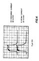
- FIG. 4 shows oscillograms of the hollow-cathode discharge and the beam current pulses for a reduction to practice of the electron gun operating at 53 kV, with a current density of 14 A/cm2, and a pulse length of 12 microseconds.
- the beam current can be controlled linearly up to a space-charge limited (SCL) level by varying the hollow-cathode discharge current, as shown in FIG. 5.
- SCL space-charge limited
- the ratio of the two currents is almost identically equal to the hollow-cathode-grid transparency.
- the 5-cm2 cathode was demonstrated to be capable of supplying 60 A/cm2 of emission over a 100 »s-long pulse by operating the hollow-cathode discharge at 300 A for 100 »s; the discharge current and voltage are shown in FIG. 6. In general, long beam pulses on the order of about 1-100 »s are preferred.
- the described electron gun is used to inject an electron beam into a waveguide structure.
- the operating characteristics of the assembly can be controlled simply by controlling the internal gas pressure. With a gas pressure in the approximate range of 0,13-0,7 Pa (1-5 mTorr), the assembly can be constructed to function as a slow-wave tube, with a microwave output. Slow-wave oscillator operation is not achieved at pressures significantly less than 0,13 Pa (1 mTorr), due to the lack of sufficient plasma to prevent space-charge blowup of the beam. With a higher pressure, in the approximate range of 1,3-3 Pa (10-20 mTorr), the assembly can function as a plasma-wave-tube with a broadband microwave and/or mm-wave radiation output.
- a slow-wave tube formed by coupling the novel electron gun with a conventional rippled waveguide housing 16 is shown in FIG. 2.
- the electron gun and waveguide housing are supplied with helium gas from a reservoir 18, and a trace amount of oxygen from a reservoir 20, through respective needle valves 22 and 24; other gas supplies such a ZrH2 gas reservoir which is heated to emit hydrogen could also be used.
- An insulating bushing 26 is provided around the exterior of the gun, with electrical connections (not shown) made to the hollow cathode 2, discharge grid 4 and anode 12 through connectors 28.
- the rippled waveguide 16 acts as a slow-wave structure to reduce the phase velocity of the electromagnetic waveguide mode so as to match the speed of the electron beam, which drifts at less than the speed of light.
- Space-charge waves on the beam can then be resonantly coupled to waveguide modes to transfer energy from the beam to the microwave fields. Since the beam is not perturbed to the first order in the transverse direction as in a free electron laser, the beam electrons interact primarily with the axial components of the microwave field, which are supported by the ripples in the waveguide. Thus, primarily transverse magnetic (TM) modes are generated.
- An output horn antenna 35 radiates the output electromagnetic energy into a preferred direction in space.
- the presence of plasma in the waveguide further amplifies the growing waves because the refractive effect of the plasma increases the wavelength of the radiation, thus increasing the coupling effect of the beam with the slow-wave structure.
- Excitation of electron-plasma wave harmonics from the beam-plasma interaction is also believed to enhance beam bunching and slow-wave coupling.
- the beam current is sufficiently high so that the gain of the microwave fields in one transit of the beam through the waveguide is substantially greater than unity.
- the invention will be able to operate as a high-power oscillator without the need for reflecting a portion of the radiation back into the waveguide to make the waveguide function as a cavity.
- a low current beam may be used in the regime where the gain is less than unity.
- reflectors can be positioned at the ends of the rippled waveguide to form a high-Q cavity. The cavity would then be able to trap the growing microwave fields and allow very narrow linewidth oscillator operation with low beam current. Reflectors usable in such a configuration are described for example in pending Patent Application Serial No.
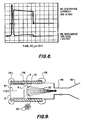
- FIG. 8 A reduction to practice of the slow-wave tube is shown in FIG. 8; elements in common with those shown in prior figures are identified by the same reference numerals, and similar electrical supply circuitry (not shown) would be used.
- the rippled waveguide 16 was implemented as a common flexible copper water pipe. The average radius was 9.2 mm, the difference between minimum and maximum radius was 2.2 mm, and the ripple period was 7.6 mm.
- the anode voltage was provided from an anode extension tube 38 fed by a lead 40 through a bushing 42. The entire assembly was furnished within a grounded vacuum housing 44, which was evacuated by a vacuum pump 46.
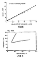
- a plot of the predicted output frequency for the slow-wave tube of FIG. 8 as a function of beam voltage is provided in FIG. 7. This curve predicts that the lowest frequency cut-off mode will be excited at about 12 GHz when the beam voltage is tuned to about 25 to 30 kV.
- the device At low beam currents, at which the growth rate of the slow waves is low and the gain per pass through the waveguide is less than unity, the device is expected to oscillate only at cut-off, because at this frequency the waveguide functions as a high-Q cavity.
- the open ends of the wave-guide reflect the microwave signals and trap the signal wave, thus allowing the wave fields to grow to large amplitude.
- the beam voltage was scanned over the 10-41 kV range. Frequency responses were observed which were consistent with the excitation of the cut-off TM01 at 12-13 GHz, which was predicted to occur at about 30 kV (see FIG. 7).
- the plasma-wave-tube application of the present invention is illustrated in FIG. 9.
- the same electron gun is used as in the slow-wave tube application, and is indicated by the same reference numerals.
- the waveguide wall need not be rippled.
- a smooth cylindrical waveguide housing 48 is provided instead of the rippled housing of the slow-wave embodiment.
- the electron beam Along with inducing a pair of counterstreaming plasma waves, the electron beam produces sufficient ions of the gas to effectively neutralize the space-charge in the beam, thus preventing space-charge blowup and keeping the beam confined without the use of magnetic fields.
- the result is a higher power output, and the avoidance of the space-charge voltage depression, axial velocity shear, complexity and expense associated with magnetic systems.
- Plasma wave tube operation was demonstrated by increasing the helium gas pressure to 2 Pa (15 mTorr), which increased the plasma density in the waveguide.
- the slow-wave oscillation frequency is less than the plasma frequency, and the plasma density is higher than 2x1012 cm ⁇ 3.
- the electron beam drives intense electron plasma waves, which nonlinearly modulate the background plasma, producing near-zero frequency plasma structures.
- the forward driven waves scatter off the structures, producing backscattered plasma waves.
- the forward and backward propagating waves couple to generate a waveguide mode at a frequency equal to twice the plasma frequency. Since the plasma is rather non-uniform, there is a spread in the plasma frequency, and consequently a broadband output microwave/mm-wave frequency.
- FIG. 10 is a series of graphs of oscilloscope traces showing the broadband output achieved with a system operated at 2 Pa (15 mTorr) of helium, a discharge voltage of 33 kV and a discharge current of 30 A.
- An X-band filter was used to detect the low end of the frequency output. Although most efficient over a range of about 8 to 12 GHz, X-band detectors are high pass filters that are also sensitive to higher frequencies. The lower limit of the output frequency was calculated to be 15 GHz, based upon the waveguide dimensions and plasma density. A frequency response up to about 40 GHz in the Ka-band was observed.
- the new electron gun described herein as part of the invention has a primary application to slow-wave tubes and plasma wave tubes, it may also be useful for other applications. These could include the use of the electron gun to drive a laser, or to expose resist in connection with electron-beam lithography.
Landscapes
- Plasma Technology (AREA)
- Electron Sources, Ion Sources (AREA)
- Microwave Tubes (AREA)
Abstract
Claims (16)
- Un canon à électrons à courant élevé, comprenant :
une cathode creuse (2) ayant de multiples orifices de sortie,
des moyens (18, 20, 22, 24) pour introduire un gaz ionisable dans la cathode,
une grille perforée (4) placée en position adjacente aux orifices de sortie multiples de la cathode, cette grille ayant des ouvertures suffisamment petites pour empêcher le passage d'un plasma,
des moyens (8, 10) pour établir une décharge électrique luminescente entre la cathode (2) et la grille (4), pour générer un plasma à l'intérieur de la cathode (2),
une anode perforée (12) du côté de la grille (4) qui est opposé à la cathode (2), et
des moyens (14) pour appliquer un potentiel électrique à l'anode (12) afin d'extraire un faisceau d'électrons (34) du plasma se trouvant derrière la grille (4),
dans lequel la cathode et l'anode (12) ont des ensembles respectifs d'ouvertures qui sont mutuellement alignées pour donner un faisceau ayant une pervéance élevée. - Le canon à électrons de la revendication 1, dans lequel la surface de cathode intérieure est formée par un métal non magnétique.
- Le canon à électrons de la revendication 1 ou 2, dans lequel la surface de cathode intérieure est formée par un métal chimiquement actif, et les moyens d'introduction de gaz (18, 20, 22, 24) comprennent des moyens (20, 24) qui sont destinés à doper le gaz avec de l'oxygène, dans la proportion de traces, pour réagir avec le métal et former un oxyde de celui-ci, ce qui a pour effet de renforcer le rendement d'émission d'électrons secondaires de la cathode (2).
- Le canon à électrons de l'une des revendications précédentes, dans lequel la cathode, la grille (4) et l'anode (12) sont courbées de manière concave par rapport au faisceau (34), pour focaliser géométriquement le faisceau.
- Le canon à électrons de l'une des revendications précédentes, dans lequel la cathode creuse (2) est cylindrique pour produire un faisceau d'électrons (34) ayant une section transversale pratiquement circulaire.
- Un oscillateur pour générer un rayonnement électromagnétique dans la gamme allant des micro-ondes aux ondes millimétriques, comprenant
un corps de guide d'ondes (16; 48)
des moyens pour introduire un gaz ionisable dans le corps de guide d'ondes (16; 48),
un canon à électrons de l'une des revendications précédentes, pour injecter un faisceau d'électrons (32, 34) dans le corps de guide d'ondes (16; 48), et
des moyens (46) pour maintenir la pression de gaz à l'intérieur du corps de guide d'ondes (16; 48) à un niveau suffisamment bas pour éviter un claquage en tension du faisceau (32, 34), et suffisamment élevé pour produire suffisamment d'ions pour neutraliser pratiquement l'expansion de la charge d'espace du faisceau,
le canon à électrons injectant le faisceau (32, 34) dans le corps de guide d'ondes (16; 48) avec une densité de courant suffisante pour ioniser au moins partiellement le gaz qui se trouve à l'intérieur, et pour générer un rayonnement électromagnétique à la pression de gaz précitée. - L'oscillateur de la revendication 6, dans lequel la pression de gaz est maintenue dans la plage approximative de 0,13 - 3 Pa (1-20 mTorr).
- L'oscillateur de la revendication 6 ou 7, réalisé sous la forme d'un tube à ondes lentes, le corps de guide d'ondes (16) ayant une paroi ondulée, dans lequel la pression de gaz est maintenue dans la plage approximative de 0,13 - 0,7 Pa (1-5 mTorr).
- L'oscillateur de la revendication 6 ou 7, réalisé sous la forme d'un tube à ondes de plasma, dans lequel la pression de gaz est maintenue dans la plage approximative de 1,3 - 3 Pa (10-20 mTorr).
- L'oscillateur de l'une des revendications 6-9, dans lequel le canon à électrons génère un faisceau ayant une densité de courant d'au moins environ 1 A/cm².
- L'oscillateur de l'une des revendications 6-10, dans lequel les moyens destinés à introduire un gaz ionisable dans le corps de guide d'ondes (16; 48) introduisent également le gaz ionisable dans le canon à électrons, à une pression approximativement égale à la pression à l'intérieur du corps de guide d'ondes (16; 48).
- L'oscillateur de l'une des revendications 6-11, dans lequel le canon à électrons comprend des moyens pour établir une décharge électrique luminescente dans le gaz ionisable qui se trouve à l'intérieur du canon, pour établir un plasma dans celui-ci, ce plasma constituant une source d'électrons pour le faisceau (32, 34).
- L'oscillateur de la revendication 12, dans lequel le canon à électrons comprend des moyens (8) pour produire la décharge sous la forme d'impulsions d'une durée d'environ 1 - 100 »s.
- L'oscillateur de l'une des revendications 6-13, dans lequel le canon à électrons injecte le faisceau d'électrons (32, 34) dans une extrémité du corps de guide d'ondes (16; 48), et comprenant en outre une antenne cornet (35) à l'extrémité opposée du corps de guide d'ondes (16; 48), pour émettre un rayonnement électromagnétique de sortie.
- Le canon à électrons et/ou l'oscillateur de l'une des revendications précédentes, dans lequel le gaz est de l'hélium.
- L'oscillateur de l'une des revendications 6-15, dans lequel le corps de guide d'ondes (16; 48) a une paroi cylindrique lisse, et un seul faisceau d'électrons est injecté dans le corps (16; 48) pour produire une paire d'ondes de plasma se propageant en sens oppose.
Applications Claiming Priority (3)
| Application Number | Priority Date | Filing Date | Title |
|---|---|---|---|
| US181279 | 1988-04-14 | ||
| US07/181,279 US4912367A (en) | 1988-04-14 | 1988-04-14 | Plasma-assisted high-power microwave generator |
| PCT/US1989/000857 WO1989010000A1 (fr) | 1988-04-14 | 1989-03-06 | Generateur de micro-ondes de haute puissance assiste par plasma |
Publications (2)
| Publication Number | Publication Date |
|---|---|
| EP0364574A1 EP0364574A1 (fr) | 1990-04-25 |
| EP0364574B1 true EP0364574B1 (fr) | 1994-06-22 |
Family
ID=22663610
Family Applications (1)
| Application Number | Title | Priority Date | Filing Date |
|---|---|---|---|
| EP89907396A Expired - Lifetime EP0364574B1 (fr) | 1988-04-14 | 1989-03-06 | Generateur de micro-ondes de haute puissance assiste par plasma |
Country Status (6)
| Country | Link |
|---|---|
| US (1) | US4912367A (fr) |
| EP (1) | EP0364574B1 (fr) |
| JP (1) | JPH088071B2 (fr) |
| DE (1) | DE68916365T2 (fr) |
| IL (1) | IL89839A (fr) |
| WO (1) | WO1989010000A1 (fr) |
Families Citing this family (31)
| Publication number | Priority date | Publication date | Assignee | Title |
|---|---|---|---|---|
| EP0502269A1 (fr) * | 1991-03-06 | 1992-09-09 | Hitachi, Ltd. | Méthode et dispositif pour traitements par plasma micro-onde |
| US5330800A (en) * | 1992-11-04 | 1994-07-19 | Hughes Aircraft Company | High impedance plasma ion implantation method and apparatus |
| US5525864A (en) * | 1994-02-07 | 1996-06-11 | Hughes Aircraft Company | RF source including slow wave tube with lateral outlet ports |
| US5668442A (en) * | 1994-05-13 | 1997-09-16 | Hughes Electronics | Plasma-assisted tube with helical slow-wave structure |
| US5537005A (en) * | 1994-05-13 | 1996-07-16 | Hughes Aircraft | High-current, low-pressure plasma-cathode electron gun |
| US5523651A (en) * | 1994-06-14 | 1996-06-04 | Hughes Aircraft Company | Plasma wave tube amplifier/primed oscillator |
| US5694005A (en) * | 1995-09-14 | 1997-12-02 | Hughes Aircraft Company | Plasma-and-magnetic field-assisted, high-power microwave source and method |
| US5834971A (en) * | 1995-11-08 | 1998-11-10 | Hughes Electronics | RF amplifier including traveling wave tube with sequential stages |
| GB9819504D0 (en) * | 1998-09-07 | 1998-10-28 | Ardavan Houshang | Apparatus for generating focused electromagnetic radiation |
| US7648100B2 (en) * | 2000-05-31 | 2010-01-19 | Kevin Kremeyer | Shock wave modification method and system |
| US6528799B1 (en) * | 2000-10-20 | 2003-03-04 | Lucent Technologies, Inc. | Device and method for suppressing space charge induced aberrations in charged-particle projection lithography systems |
| US6864636B1 (en) * | 2002-07-25 | 2005-03-08 | Mark J. Hagmann | Apparatus, method, and system for a laser-assisted field emission microwave signal generator |
| JP4878782B2 (ja) * | 2005-07-05 | 2012-02-15 | シャープ株式会社 | プラズマ処理装置及びプラズマ処理方法 |
| US7606592B2 (en) | 2005-09-19 | 2009-10-20 | Becker Charles D | Waveguide-based wireless distribution system and method of operation |
| WO2009025803A1 (fr) | 2007-08-20 | 2009-02-26 | Kevin Kremeyer | Systèmes de dépôt d'énergie, équipement et procédés permettant de modifier et de commander des ondes de choc et un écoulement supersonique |
| US20090096380A1 (en) * | 2007-10-12 | 2009-04-16 | Brian Scanlan | System and method for producing energetic particles by gas discharge in deuterium containing gas |
| JP5129555B2 (ja) * | 2007-12-05 | 2013-01-30 | 独立行政法人日本原子力研究開発機構 | ビーム終端方法及びビーム終端装置 |
| US8401151B2 (en) * | 2009-12-16 | 2013-03-19 | General Electric Company | X-ray tube for microsecond X-ray intensity switching |
| US8900403B2 (en) | 2011-05-10 | 2014-12-02 | Lam Research Corporation | Semiconductor processing system having multiple decoupled plasma sources |
| US9111728B2 (en) | 2011-04-11 | 2015-08-18 | Lam Research Corporation | E-beam enhanced decoupled source for semiconductor processing |
| WO2012173864A1 (fr) * | 2011-06-17 | 2012-12-20 | The Curators Of The University Of Missouri | Systèmes et procédés pour générer un plasma d'air haute densité auto-confiné |
| US8513619B1 (en) * | 2012-05-10 | 2013-08-20 | Kla-Tencor Corporation | Non-planar extractor structure for electron source |
| US9368313B1 (en) | 2012-06-06 | 2016-06-14 | International Technology Center | Electronic amplifier device |
| US9224572B2 (en) | 2012-12-18 | 2015-12-29 | General Electric Company | X-ray tube with adjustable electron beam |
| US9484179B2 (en) | 2012-12-18 | 2016-11-01 | General Electric Company | X-ray tube with adjustable intensity profile |
| US10669653B2 (en) | 2015-06-18 | 2020-06-02 | Kevin Kremeyer | Directed energy deposition to facilitate high speed applications |
| US20170325326A1 (en) * | 2016-05-05 | 2017-11-09 | The Board Of Trustees Of The Leland Stanford Junior University | Apparatus for mm-wave radiation generation utilizing whispering gallery mode resonators |
| JP6569704B2 (ja) * | 2017-07-28 | 2019-09-04 | 三菱電機株式会社 | 電磁波発生装置 |
| CN109300757B (zh) * | 2018-11-22 | 2023-07-18 | 中国科学院空间应用工程与技术中心 | 微波ecr等离子体阴极环形束电子枪及3d打印方法 |
| CN110806148B (zh) * | 2019-10-15 | 2022-02-01 | 深圳市思博克科技有限公司 | 一种用于车船迫停的紧凑型窄带高功率微波源 |
| CN117012612A (zh) * | 2023-05-22 | 2023-11-07 | 电子科技大学 | 一种利用等离子体激发电磁波的装置 |
Family Cites Families (14)
| Publication number | Priority date | Publication date | Assignee | Title |
|---|---|---|---|---|
| US2848649A (en) * | 1952-01-24 | 1958-08-19 | Itt | Electromagnetic wave generator |
| US3090019A (en) * | 1959-02-24 | 1963-05-14 | Andrew Corp | Flexible waveguide |
| US3099768A (en) * | 1959-03-25 | 1963-07-30 | Gen Electric | Low noise electron beam plasma amplifier |
| NL260047A (fr) * | 1961-01-13 | |||
| FR1377434A (fr) * | 1963-09-20 | 1964-11-06 | Csf | Tube haute fréquence fonctionnant par interaction entre faisceau et plasma |
| US3852633A (en) * | 1972-12-13 | 1974-12-03 | Varian Associates | Gridded electron gun |
| US3831052A (en) * | 1973-05-25 | 1974-08-20 | Hughes Aircraft Co | Hollow cathode gas discharge device |
| US4025818A (en) * | 1976-04-20 | 1977-05-24 | Hughes Aircraft Company | Wire ion plasma electron gun |
| JPS6011417B2 (ja) * | 1979-10-23 | 1985-03-26 | 株式会社東芝 | ホロ−カソ−ド放電装置 |
| JPS6043620B2 (ja) * | 1982-11-25 | 1985-09-28 | 日新ハイボルテージ株式会社 | マイクロ波イオン源 |
| US4642522A (en) * | 1984-06-18 | 1987-02-10 | Hughes Aircraft Company | Wire-ion-plasma electron gun employing auxiliary grid |
| US4707637A (en) * | 1986-03-24 | 1987-11-17 | Hughes Aircraft Company | Plasma-anode electron gun |
| US4697272A (en) * | 1986-05-09 | 1987-09-29 | Hughes Aircraft Company | Corrugated reflector apparatus and method for free electron lasers |
| US4745336A (en) * | 1986-05-27 | 1988-05-17 | Ga Technologies Inc. | Microwave generation by virtual cathode with phase velocity matching |
-
1988
- 1988-04-14 US US07/181,279 patent/US4912367A/en not_active Expired - Lifetime
-
1989
- 1989-03-06 JP JP1506792A patent/JPH088071B2/ja not_active Expired - Lifetime
- 1989-03-06 WO PCT/US1989/000857 patent/WO1989010000A1/fr not_active Ceased
- 1989-03-06 EP EP89907396A patent/EP0364574B1/fr not_active Expired - Lifetime
- 1989-03-06 DE DE68916365T patent/DE68916365T2/de not_active Expired - Fee Related
- 1989-04-04 IL IL89839A patent/IL89839A/xx not_active IP Right Cessation
Non-Patent Citations (1)
| Title |
|---|
| IEEE International Conference on Plasma Science, Conference Record - Abstracts, 1-3 June 1987, Arlington, VA, IEEE (New York, US), R.W. Schumacher et al: "Scalling of millimeter-wave radiation generated by counterstreaming beams in a plasma-filled waveguide", page 41, abstract no. 2Y10, see the whole abstract * |
Also Published As
| Publication number | Publication date |
|---|---|
| JPH088071B2 (ja) | 1996-01-29 |
| DE68916365D1 (de) | 1994-07-28 |
| EP0364574A1 (fr) | 1990-04-25 |
| IL89839A (en) | 1993-01-31 |
| WO1989010000A1 (fr) | 1989-10-19 |
| DE68916365T2 (de) | 1994-10-06 |
| US4912367A (en) | 1990-03-27 |
| JPH03501074A (ja) | 1991-03-07 |
Similar Documents
| Publication | Publication Date | Title |
|---|---|---|
| EP0364574B1 (fr) | Generateur de micro-ondes de haute puissance assiste par plasma | |
| WO1989010000A2 (fr) | Generateur de micro-ondes de haute puissance assiste par plasma | |
| Nusinovich et al. | Recent progress in the development of plasma-filled traveling-wave tubes and backward-wave oscillators | |
| US3931589A (en) | Perforated wall hollow-cathode ion laser | |
| US5537005A (en) | High-current, low-pressure plasma-cathode electron gun | |
| Goebel et al. | Advances in plasma-filled microwave sources | |
| US4916361A (en) | Plasma wave tube | |
| US4888776A (en) | Ribbon beam free electron laser | |
| US4313072A (en) | Light modulated switches and radio frequency emitters | |
| US5159241A (en) | Single body relativistic magnetron | |
| US5134641A (en) | Plasma x-ray tube, in particular for x-ray preionizing of gas lasers, and an electron gun using the plasma x-ray tube | |
| Miller | Pulse shortening in high-peak-power reltron tubes | |
| Goebel et al. | Performance and pulse shortening effects in a 200-kV PASOTRON/sup TM/HPM source | |
| US5668442A (en) | Plasma-assisted tube with helical slow-wave structure | |
| Goebel et al. | PASOTRON high-power microwave source performance | |
| KR20020004934A (ko) | 선형이온빔의 플라즈마소스 | |
| US9368313B1 (en) | Electronic amplifier device | |
| EP0403583B1 (fr) | Procede et tube a ondes de plasma | |
| US4024465A (en) | Generation of corona for laser excitation | |
| US3800244A (en) | Rf resonance electron excitation | |
| Thumm | Present developments and status of electron sources for high power gyrotron tubes and free electron masers | |
| Loza et al. | Relativistic Cherenkov plasma maser of microsecond pulse duration | |
| RU2239257C1 (ru) | Диодный узел для генератора сверхвысокочастотного излучения | |
| US5523651A (en) | Plasma wave tube amplifier/primed oscillator | |
| US11810763B2 (en) | Distributed ground single antenna ion source |
Legal Events
| Date | Code | Title | Description |
|---|---|---|---|
| PUAI | Public reference made under article 153(3) epc to a published international application that has entered the european phase |
Free format text: ORIGINAL CODE: 0009012 |
|
| 17P | Request for examination filed |
Effective date: 19891213 |
|
| AK | Designated contracting states |
Kind code of ref document: A1 Designated state(s): DE FR GB IT SE |
|
| 17Q | First examination report despatched |
Effective date: 19920117 |
|
| GRAA | (expected) grant |
Free format text: ORIGINAL CODE: 0009210 |
|
| AK | Designated contracting states |
Kind code of ref document: B1 Designated state(s): DE FR GB IT SE |
|
| REF | Corresponds to: |
Ref document number: 68916365 Country of ref document: DE Date of ref document: 19940728 |
|
| ET | Fr: translation filed | ||
| ITF | It: translation for a ep patent filed | ||
| EAL | Se: european patent in force in sweden |
Ref document number: 89907396.9 |
|
| PG25 | Lapsed in a contracting state [announced via postgrant information from national office to epo] |
Ref country code: SE Effective date: 19950307 |
|
| PLBE | No opposition filed within time limit |
Free format text: ORIGINAL CODE: 0009261 |
|
| STAA | Information on the status of an ep patent application or granted ep patent |
Free format text: STATUS: NO OPPOSITION FILED WITHIN TIME LIMIT |
|
| 26N | No opposition filed | ||
| EUG | Se: european patent has lapsed |
Ref document number: 89907396.9 |
|
| REG | Reference to a national code |
Ref country code: GB Ref legal event code: 732E |
|
| REG | Reference to a national code |
Ref country code: FR Ref legal event code: TP Ref country code: FR Ref legal event code: CD Ref country code: FR Ref legal event code: CA |
|
| REG | Reference to a national code |
Ref country code: GB Ref legal event code: IF02 |
|
| PGFP | Annual fee paid to national office [announced via postgrant information from national office to epo] |
Ref country code: FR Payment date: 20020211 Year of fee payment: 14 |
|
| PGFP | Annual fee paid to national office [announced via postgrant information from national office to epo] |
Ref country code: GB Payment date: 20020220 Year of fee payment: 14 |
|
| PGFP | Annual fee paid to national office [announced via postgrant information from national office to epo] |
Ref country code: DE Payment date: 20020221 Year of fee payment: 14 |
|
| PG25 | Lapsed in a contracting state [announced via postgrant information from national office to epo] |
Ref country code: GB Free format text: LAPSE BECAUSE OF NON-PAYMENT OF DUE FEES Effective date: 20030306 |
|
| PG25 | Lapsed in a contracting state [announced via postgrant information from national office to epo] |
Ref country code: DE Free format text: LAPSE BECAUSE OF NON-PAYMENT OF DUE FEES Effective date: 20031001 |
|
| GBPC | Gb: european patent ceased through non-payment of renewal fee |
Effective date: 20030306 |
|
| PG25 | Lapsed in a contracting state [announced via postgrant information from national office to epo] |
Ref country code: FR Free format text: LAPSE BECAUSE OF NON-PAYMENT OF DUE FEES Effective date: 20031127 |
|
| REG | Reference to a national code |
Ref country code: FR Ref legal event code: ST |
|
| PG25 | Lapsed in a contracting state [announced via postgrant information from national office to epo] |
Ref country code: IT Free format text: LAPSE BECAUSE OF NON-PAYMENT OF DUE FEES;WARNING: LAPSES OF ITALIAN PATENTS WITH EFFECTIVE DATE BEFORE 2007 MAY HAVE OCCURRED AT ANY TIME BEFORE 2007. THE CORRECT EFFECTIVE DATE MAY BE DIFFERENT FROM THE ONE RECORDED. Effective date: 20050306 |