EP0364577B1 - Dispositif de detection de deconnexion de lampes - Google Patents
Dispositif de detection de deconnexion de lampes Download PDFInfo
- Publication number
- EP0364577B1 EP0364577B1 EP88902925A EP88902925A EP0364577B1 EP 0364577 B1 EP0364577 B1 EP 0364577B1 EP 88902925 A EP88902925 A EP 88902925A EP 88902925 A EP88902925 A EP 88902925A EP 0364577 B1 EP0364577 B1 EP 0364577B1
- Authority
- EP
- European Patent Office
- Prior art keywords
- lamp
- lamps
- winding
- power line
- core
- Prior art date
- Legal status (The legal status is an assumption and is not a legal conclusion. Google has not performed a legal analysis and makes no representation as to the accuracy of the status listed.)
- Expired - Lifetime
Links
Images

Classifications
-
- G—PHYSICS
- G01—MEASURING; TESTING
- G01F—MEASURING VOLUME, VOLUME FLOW, MASS FLOW OR LIQUID LEVEL; METERING BY VOLUME
- G01F23/00—Indicating or measuring liquid level or level of fluent solid material, e.g. indicating in terms of volume or indicating by means of an alarm
- G01F23/30—Indicating or measuring liquid level or level of fluent solid material, e.g. indicating in terms of volume or indicating by means of an alarm by floats
- G01F23/32—Indicating or measuring liquid level or level of fluent solid material, e.g. indicating in terms of volume or indicating by means of an alarm by floats using rotatable arms or other pivotable transmission elements
- G01F23/38—Indicating or measuring liquid level or level of fluent solid material, e.g. indicating in terms of volume or indicating by means of an alarm by floats using rotatable arms or other pivotable transmission elements using magnetically actuated indicating means
-
- G—PHYSICS
- G01—MEASURING; TESTING
- G01R—MEASURING ELECTRIC VARIABLES; MEASURING MAGNETIC VARIABLES
- G01R31/00—Arrangements for testing electric properties; Arrangements for locating electric faults; Arrangements for electrical testing characterised by what is being tested not provided for elsewhere
- G01R31/44—Testing lamps
-
- H—ELECTRICITY
- H05—ELECTRIC TECHNIQUES NOT OTHERWISE PROVIDED FOR
- H05B—ELECTRIC HEATING; ELECTRIC LIGHT SOURCES NOT OTHERWISE PROVIDED FOR; CIRCUIT ARRANGEMENTS FOR ELECTRIC LIGHT SOURCES, IN GENERAL
- H05B47/00—Circuit arrangements for operating light sources in general, i.e. where the type of light source is not relevant
- H05B47/20—Responsive to malfunctions or to light source life; for protection
- H05B47/23—Responsive to malfunctions or to light source life; for protection of two or more light sources connected in series
- H05B47/235—Responsive to malfunctions or to light source life; for protection of two or more light sources connected in series with communication between the lamps and a central unit
Definitions
- This invention relates to a device for detecting the failure or disconnection of any of a plurality of electric lamps connected in series and has particular reference to such a device which is suitably used for detecting the failure of any of a large number of taxiway or guide lamps illuminating the runway of an airfield.
- DE-0-36 35 682 describes a lamp failure detecting device for use with each of a plurality of serially connected lamps, each device comprising: a means connected in series to the corresponding lamp for detecting a respective lamp current; a signal generator operable by an output voltage of said detecting means; and a means connected in series to the corresponding lamp for feeding an output signal from said signal generator back to a lamp power line.
- the present invention seeks to provide a device for detecting lamp failure which is capable of preforming accurate detection and remote central monitoring of a large number of electric lamps.
- a lamp failure detecting device which essentially comprises a transformer means disposed on a lamp power line and having a core, a first winding wound on said core and connected in series to the corresponding lamp and a second winding wound on said lamp power line through said core; and an oscillator operating on the output voltage of said second winding and generating a predetermined frequency, for supplying an output signal having the predetermined frequency from said oscillator onto said lamp power line characterised in that the oscillator supplies an output signal to the lamp power line via a third winding wound on said core.
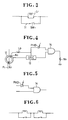
- FIG. 1 is a circuit diagram on enlarged scale of a lamp L1 having a filament 10.
- a short-circuitng circuit 11 is provided for giving a short circuit between the opposite terminals of the lamp filament 10.
- the circuit 11 is conventional, including a switch SW1 which operates to close the circuit 11 in the event of lamp failure.
- the circuit 11 is connected to a power line P1 at points A and B.
- a core 12 is provided on the power line P1 between one terminal of the lamp filament 10 and the connection point A.
- the core 12 has wound thereon a first winding N1, which is an extension of the power line P1, a second winding N2 for extracting power from the first winding N1 via core 12 and a third winding N3 for transferring a signal S1 to the first winding N1 to provide the lamp L1 with a signal of a predetermined frequency f1.
- the second winding N2 functions as a means of detecting a current flow through the power line P1 to turn on the lamp L1.
- a signal generator 13 is connected to the output terminal of the second winding N2 and designed as an oscillator to be excited by the output voltage of the second winding N2 to generate a specific frequency f1.
- the output of the signal generator 13 is connected to the third winding N3 to feed back its output signal as a current through the core 12 to the power line P1 so that the lamp L1 is normally (i.e. when turned on) supplied with a signal of frequency f1.
- Designated at L p is an inductance adapted to prohibit entry of the feedback signal from the third winding N3 into the signal generator 13 and allow passage of the frequency components of the lamp power current alone in the circuit.
- the detecting device for the lamp L1 is used commonly, as shown in FIG. 2, for each of the remaining lamps L1 - L n with their respective predetermined frequencies f2 - f n supplied in superimposed relation.
- filters F1 - F n in the lamp power circuit assigned to corresponding lamps L1 - L n and adapted to extract their respective feedback signals; namely, feedback frequencies.
- Central monitoring of the lamp operation is effected by the circuit arrangement above described in which failure of the filament 10 in the lamp L1 causes the switch SW1 to close to permit current flow through the circuit 11, whereupon the current to the lamp L1 and hence the signal f1 from the signal generator 13 are discontinued and the frequency component f1 in the lamp circuit can no longer be detected by the filter F1 thereby ascertaining the occurrence of failure of the lamp L1.
- lamp monitoring can also be effected with the core 12 provided on the short-circuiting line P2, in which case the feedback signal does not flow through the lamp circuit as long as the lamp is on, but in the event of failure begins to flow with a frequency corresponding to that particular lamp which has failed and will be received by the corresponding one of the filters (F1 - F n ) thereby detecting the occurrence of failure of which particular one of the serially connected lamps.
- FIGS. 3 and 4 Another embodiment of the invention is illustrated in FIGS. 3 and 4, in which the filament 10 is broken but with the current continued to flow through the power line P1 and the signal generator 13 produces a feedback signal of frequency f1.
- the circuit arrangement shown in FIG. 4 incorporates a photodiode PHD adjacent to the lamp. In the event of failure of the lamp L1, no current flows through the photodiode PHD with no output at an AND-circuit 14 and hence no feedback signal received at the filter F1, indicating that the lamp L1 has failed.
- the circuit may be a negative input AND-circuit so that the output of the photodiode PHD becomes a negative input, as shown in FIG. 5.
- the detecting device embodying the present invention is provided in each of the numerous serially connected lamp circuits so that the lamp operation can be remotely controlled and failure of any of the many lamps can be readily detected.
- the inventive device may be most suitably used to control the operation of for example guide lamps illuminating the runway of an airfield so as to contribute to safety in the take-off and landing of air planes.
Landscapes
- Physics & Mathematics (AREA)
- General Physics & Mathematics (AREA)
- Fluid Mechanics (AREA)
- Circuit Arrangement For Electric Light Sources In General (AREA)
Abstract
Claims (2)
- Dispositif de détection de panne d'une ampoule électrique pour une utilisation avec chacune d'une pluralité d'ampoules électriques montées en série, chaque dispositif comportant : un moyen transformateur disposé sur une ligne d'alimentation électrique (P₁) d'une ampoule et possédant un noyau (12), un premier enroulement (N₁) bobiné sur ledit noyau (12) et monté en série avec l'ampoule correspondante (L₁-Ln) et un second enroulement (N₂) bobiné sur ladite ligne d'alimentation électrique (P₁) de l'ampoule par l'intermédiaire dudit noyau (12) ;
et un oscillateur (13) agissant sur la tension de sortie dudit second enroulement (N₂) et produisant une fréquence prédéterminée (f₁-fn), pour délivrer un signal de sortie ayant la fréquence prédéterminée (f₁-fn) dudit oscillateur (13) sur la ligne d'alimentation électrique (P₁) de ladite ampoule, caractérisé en ce que l'oscillateur (13) délivre un signal de sortie à la ligne d'alimentation électrique (P₁) de l'ampoule par l'intermédiaire d'un troisième enroulement (N₃) bobiné sur ledit noyau (12). - Dispositif de détection de panne d'ampoule électrique selon la revendication 1, qui comprend en outre une photodiode (PHD) située à proximité de chacune de la pluralité d'ampoules montées en série (L₁, Ln) et un circuit ET (14) respectif pour produire un signal de sortie d'une fréquence prédéterminée respective (f₁-fn) lors d'une intersection logique du signal de sortie de ladite photodiode (PHD) et du signal de sortie dudit oscillateur (13).
Applications Claiming Priority (1)
| Application Number | Priority Date | Filing Date | Title |
|---|---|---|---|
| PCT/JP1988/000307 WO1989009533A1 (fr) | 1988-03-25 | 1988-03-25 | Dispositif de detection de deconnexion de lampes |
Publications (3)
| Publication Number | Publication Date |
|---|---|
| EP0364577A1 EP0364577A1 (fr) | 1990-04-25 |
| EP0364577A4 EP0364577A4 (en) | 1990-12-05 |
| EP0364577B1 true EP0364577B1 (fr) | 1995-01-04 |
Family
ID=13930587
Family Applications (1)
| Application Number | Title | Priority Date | Filing Date |
|---|---|---|---|
| EP88902925A Expired - Lifetime EP0364577B1 (fr) | 1988-03-25 | 1988-03-25 | Dispositif de detection de deconnexion de lampes |
Country Status (4)
| Country | Link |
|---|---|
| US (1) | US5105124A (fr) |
| EP (1) | EP0364577B1 (fr) |
| DE (1) | DE3852701T2 (fr) |
| WO (1) | WO1989009533A1 (fr) |
Cited By (1)
| Publication number | Priority date | Publication date | Assignee | Title |
|---|---|---|---|---|
| DE102008054203A1 (de) | 2008-10-31 | 2010-06-10 | Adb N.V | Vorrichtung zur Flugfeldbefeuerung eines Flughafens |
Families Citing this family (11)
| Publication number | Priority date | Publication date | Assignee | Title |
|---|---|---|---|---|
| DE4143097C3 (de) * | 1991-12-27 | 1999-10-07 | Aenea Angewandte En Und Automa | Anordnung und Anzeige zur Ortsbestimmung defekter Lampen in Flugplatzbefeuerungsanlagen mit digitalem Lampen-"Intakt"-Signal |
| IT1256034B (it) * | 1992-08-07 | 1995-11-21 | Apparecchiatura per la regolazione a distanza della potenza luminosa di ogni singola lampada e per il comando a distanza della sua accensione e spegnimento in impianti di illuminazione in serie o in parallelo tramite onde convogliate | |
| US5325023A (en) * | 1993-03-03 | 1994-06-28 | Pacific Scientific Company | Outdoor lighting control apparatus |
| US5412222A (en) * | 1993-06-30 | 1995-05-02 | Eastman Kodak Company | Storage phosphor reader having erase lamp feature failure detection |
| US5397963A (en) * | 1993-09-02 | 1995-03-14 | New Bedford Panoramex Corporation | Subsystem and method for detecting lamp failure |
| US5446277A (en) * | 1993-12-27 | 1995-08-29 | Rutter; Robert E. | Automated lamp monitoring system for comparing light intensities with a preselected valve |
| US5654794A (en) * | 1995-01-13 | 1997-08-05 | Devore Aviation | Portable light intensity monitoring systems |
| IT1299901B1 (it) * | 1998-03-13 | 2000-04-04 | Ocem Spa | Dispositivo di sicurezza per impianti di illuminazione costituiti da una pluralita' di carichi collegati in serie. |
| US6183116B1 (en) | 1999-02-22 | 2001-02-06 | New Bedford Panoramex Corporation | Lamp retainer ring and lampholder assembly |
| RU2009102052A (ru) * | 2006-06-23 | 2010-07-27 | Конинклейке Филипс Электроникс Н.В. (Nl) | Способ и устройство, предназначенные для возбуждения матрицы источников света |
| ES2707999T3 (es) | 2014-04-10 | 2019-04-08 | Cooper Technologies Co | Configuración inalámbrica y diagnósticos de accesorios de iluminación de campo de aviación |
Family Cites Families (13)
| Publication number | Priority date | Publication date | Assignee | Title |
|---|---|---|---|---|
| GB1073068A (en) * | 1965-06-16 | 1967-06-21 | British Lighting Ind Ltd | Series operation of electric lamps |
| GB1092795A (en) * | 1966-01-14 | 1967-11-29 | Lucas Industries Ltd | Battery charging systems for use in road vehicles |
| US3898913A (en) * | 1973-09-24 | 1975-08-12 | Bendix Corp | Solenoid control valve for hydraulic brake booster |
| US3964040A (en) * | 1974-10-29 | 1976-06-15 | Vapor Corporation | Circuit for detecting burned-out lamp for a buoy lamp changer |
| US3995262A (en) * | 1975-06-25 | 1976-11-30 | Welwyn Electric Limited | Electric lamp failure indicator circuit |
| JPS5833679Y2 (ja) * | 1978-08-31 | 1983-07-27 | 昭和電線電纜株式会社 | 航空照明設備の球切れ検出装置 |
| FR2461626A1 (fr) * | 1979-07-16 | 1981-02-06 | Jeumont Schneider | Dispositif d'alimentation et de controle du bon fonctionnement d'un feu de signalisation ferroviaire |
| SU852658A2 (ru) * | 1979-11-30 | 1981-08-07 | Омский Институт Инженеров Железнодорожноготранспорта | Токоприемник дл токосъема с токопрово-д щЕгО РЕльСА |
| JPS5697991A (en) * | 1979-12-31 | 1981-08-07 | Showa Electric Wire & Cable Co | Method of displaying disconnection |
| US4527095A (en) * | 1982-07-28 | 1985-07-02 | Herring Robert W | Lamp circuit apparatus |
| GB2135540A (en) * | 1983-02-17 | 1984-08-30 | Pa Consulting Services | Lamp failure alarm |
| FR2592718B1 (fr) * | 1986-01-09 | 1988-08-26 | Forclum Force Lumiere Elect | Procede et systeme de surveillance des defaillances d'au moins une source de rayonnement lumineux |
| DE3635682A1 (de) * | 1986-10-21 | 1988-04-28 | Bbc Brown Boveri & Cie | Ueberwachungseinrichtung fuer den lampenausfall bei flugplatzfeuerungsanlagen |
-
1988
- 1988-03-25 WO PCT/JP1988/000307 patent/WO1989009533A1/fr not_active Ceased
- 1988-03-25 EP EP88902925A patent/EP0364577B1/fr not_active Expired - Lifetime
- 1988-03-25 DE DE3852701T patent/DE3852701T2/de not_active Expired - Fee Related
-
1989
- 1989-11-24 US US07/444,139 patent/US5105124A/en not_active Expired - Fee Related
Cited By (1)
| Publication number | Priority date | Publication date | Assignee | Title |
|---|---|---|---|---|
| DE102008054203A1 (de) | 2008-10-31 | 2010-06-10 | Adb N.V | Vorrichtung zur Flugfeldbefeuerung eines Flughafens |
Also Published As
| Publication number | Publication date |
|---|---|
| US5105124A (en) | 1992-04-14 |
| WO1989009533A1 (fr) | 1989-10-05 |
| DE3852701D1 (de) | 1995-02-16 |
| DE3852701T2 (de) | 1995-09-28 |
| EP0364577A4 (en) | 1990-12-05 |
| EP0364577A1 (fr) | 1990-04-25 |
Similar Documents
| Publication | Publication Date | Title |
|---|---|---|
| US5027114A (en) | Ground guidance system for airplanes | |
| EP0364577A1 (fr) | Dispositif de detection de deconnexion de lampes | |
| US4675574A (en) | Monitoring device for airfield lighting system | |
| US4216413A (en) | System for sequentially operating flash lamps in repeated sequences | |
| US5034659A (en) | Lamp circuit with disconnected lamp detecting device | |
| US4583086A (en) | Circuit for monitoring the operating condition of an electric load | |
| US4144478A (en) | Lamp system take control dimming circuit | |
| US5768077A (en) | Earthing wire disconnection detection apparatus and leakage detection apparatus having an earthing wire disconnection detection function conductor | |
| US3964040A (en) | Circuit for detecting burned-out lamp for a buoy lamp changer | |
| CN110441637A (zh) | 一种离子风机高压监测装置 | |
| US4937504A (en) | Time delay initialization circuit | |
| US3710157A (en) | Method of monitoring airport runway end identification lamps | |
| US4568923A (en) | Fire alarm system | |
| US4712020A (en) | Bias control circuit for RF switch | |
| US4731528A (en) | Failsafe logic circuit wherein the phototransistor of a preceding optocoupler is connected in series with the photodiode of a succeeding optocoupler | |
| US5081399A (en) | Power supply systems for neon lights | |
| JPS6216000B2 (fr) | ||
| US4264950A (en) | Intrinsically safe regulated power supply | |
| DE4143097C3 (de) | Anordnung und Anzeige zur Ortsbestimmung defekter Lampen in Flugplatzbefeuerungsanlagen mit digitalem Lampen-"Intakt"-Signal | |
| JP2681294B2 (ja) | ランプの断芯検出装置 | |
| SU862166A1 (ru) | Выходной каскад приемника частотного сигнала | |
| JP3111095B2 (ja) | 炎検出装置 | |
| JP2708215B2 (ja) | 断芯検出装置 | |
| JP2709954B2 (ja) | ランプ断芯検出装置 | |
| KR900008580Y1 (ko) | 방전램프의 동작 감시회로 |
Legal Events
| Date | Code | Title | Description |
|---|---|---|---|
| PUAI | Public reference made under article 153(3) epc to a published international application that has entered the european phase |
Free format text: ORIGINAL CODE: 0009012 |
|
| 17P | Request for examination filed |
Effective date: 19891128 |
|
| AK | Designated contracting states |
Kind code of ref document: A1 Designated state(s): DE FR GB IT SE |
|
| A4 | Supplementary search report drawn up and despatched |
Effective date: 19901015 |
|
| AK | Designated contracting states |
Kind code of ref document: A4 Designated state(s): DE FR GB IT SE |
|
| 17Q | First examination report despatched |
Effective date: 19921120 |
|
| GRAA | (expected) grant |
Free format text: ORIGINAL CODE: 0009210 |
|
| ITF | It: translation for a ep patent filed | ||
| AK | Designated contracting states |
Kind code of ref document: B1 Designated state(s): DE FR GB IT SE |
|
| EAL | Se: european patent in force in sweden |
Ref document number: 88902925.2 |
|
| REF | Corresponds to: |
Ref document number: 3852701 Country of ref document: DE Date of ref document: 19950216 |
|
| ET | Fr: translation filed | ||
| PLBE | No opposition filed within time limit |
Free format text: ORIGINAL CODE: 0009261 |
|
| STAA | Information on the status of an ep patent application or granted ep patent |
Free format text: STATUS: NO OPPOSITION FILED WITHIN TIME LIMIT |
|
| 26N | No opposition filed | ||
| PGFP | Annual fee paid to national office [announced via postgrant information from national office to epo] |
Ref country code: GB Payment date: 20010122 Year of fee payment: 14 |
|
| PGFP | Annual fee paid to national office [announced via postgrant information from national office to epo] |
Ref country code: FR Payment date: 20010130 Year of fee payment: 14 |
|
| PGFP | Annual fee paid to national office [announced via postgrant information from national office to epo] |
Ref country code: DE Payment date: 20010131 Year of fee payment: 14 |
|
| PGFP | Annual fee paid to national office [announced via postgrant information from national office to epo] |
Ref country code: SE Payment date: 20010205 Year of fee payment: 14 |
|
| REG | Reference to a national code |
Ref country code: GB Ref legal event code: IF02 |
|
| PG25 | Lapsed in a contracting state [announced via postgrant information from national office to epo] |
Ref country code: GB Free format text: LAPSE BECAUSE OF NON-PAYMENT OF DUE FEES Effective date: 20020325 |
|
| PG25 | Lapsed in a contracting state [announced via postgrant information from national office to epo] |
Ref country code: SE Free format text: LAPSE BECAUSE OF NON-PAYMENT OF DUE FEES Effective date: 20020326 |
|
| PG25 | Lapsed in a contracting state [announced via postgrant information from national office to epo] |
Ref country code: DE Free format text: LAPSE BECAUSE OF NON-PAYMENT OF DUE FEES Effective date: 20021001 |
|
| EUG | Se: european patent has lapsed |
Ref document number: 88902925.2 |
|
| GBPC | Gb: european patent ceased through non-payment of renewal fee |
Effective date: 20020325 |
|
| PG25 | Lapsed in a contracting state [announced via postgrant information from national office to epo] |
Ref country code: FR Free format text: LAPSE BECAUSE OF NON-PAYMENT OF DUE FEES Effective date: 20021129 |
|
| REG | Reference to a national code |
Ref country code: FR Ref legal event code: ST |
|
| PG25 | Lapsed in a contracting state [announced via postgrant information from national office to epo] |
Ref country code: IT Free format text: LAPSE BECAUSE OF NON-PAYMENT OF DUE FEES;WARNING: LAPSES OF ITALIAN PATENTS WITH EFFECTIVE DATE BEFORE 2007 MAY HAVE OCCURRED AT ANY TIME BEFORE 2007. THE CORRECT EFFECTIVE DATE MAY BE DIFFERENT FROM THE ONE RECORDED. Effective date: 20050325 |