EP0364586A1 - Disk recording apparatus - Google Patents
Disk recording apparatus Download PDFInfo
- Publication number
- EP0364586A1 EP0364586A1 EP88910130A EP88910130A EP0364586A1 EP 0364586 A1 EP0364586 A1 EP 0364586A1 EP 88910130 A EP88910130 A EP 88910130A EP 88910130 A EP88910130 A EP 88910130A EP 0364586 A1 EP0364586 A1 EP 0364586A1
- Authority
- EP
- European Patent Office
- Prior art keywords
- recording
- data
- disk
- recorded
- abnormal condition
- Prior art date
- Legal status (The legal status is an assumption and is not a legal conclusion. Google has not performed a legal analysis and makes no representation as to the accuracy of the status listed.)
- Granted
Links
Images


Classifications
-
- G—PHYSICS
- G11—INFORMATION STORAGE
- G11B—INFORMATION STORAGE BASED ON RELATIVE MOVEMENT BETWEEN RECORD CARRIER AND TRANSDUCER
- G11B20/00—Signal processing not specific to the method of recording or reproducing; Circuits therefor
- G11B20/10—Digital recording or reproducing
- G11B20/12—Formatting, e.g. arrangement of data block or words on the record carriers
- G11B20/1217—Formatting, e.g. arrangement of data block or words on the record carriers on discs
- G11B20/1251—Formatting, e.g. arrangement of data block or words on the record carriers on discs for continuous data, e.g. digitised analog information signals, pulse code modulated [PCM] data
-
- G—PHYSICS
- G11—INFORMATION STORAGE
- G11B—INFORMATION STORAGE BASED ON RELATIVE MOVEMENT BETWEEN RECORD CARRIER AND TRANSDUCER
- G11B7/00—Recording or reproducing by optical means, e.g. recording using a thermal beam of optical radiation by modifying optical properties or the physical structure, reproducing using an optical beam at lower power by sensing optical properties; Record carriers therefor
- G11B7/007—Arrangement of the information on the record carrier, e.g. form of tracks, actual track shape, e.g. wobbled, or cross-section, e.g. v-shaped; Sequential information structures, e.g. sectoring or header formats within a track
- G11B7/00736—Auxiliary data, e.g. lead-in, lead-out, Power Calibration Area [PCA], Burst Cutting Area [BCA], control information
-
- G—PHYSICS
- G11—INFORMATION STORAGE
- G11B—INFORMATION STORAGE BASED ON RELATIVE MOVEMENT BETWEEN RECORD CARRIER AND TRANSDUCER
- G11B11/00—Recording on or reproducing from the same record carrier wherein for these two operations the methods are covered by different main groups of groups G11B3/00 - G11B7/00 or by different subgroups of group G11B9/00; Record carriers therefor
- G11B11/10—Recording on or reproducing from the same record carrier wherein for these two operations the methods are covered by different main groups of groups G11B3/00 - G11B7/00 or by different subgroups of group G11B9/00; Record carriers therefor using recording by magnetic means or other means for magnetisation or demagnetisation of a record carrier, e.g. light induced spin magnetisation; Demagnetisation by thermal or stress means in the presence or not of an orienting magnetic field
- G11B11/105—Recording on or reproducing from the same record carrier wherein for these two operations the methods are covered by different main groups of groups G11B3/00 - G11B7/00 or by different subgroups of group G11B9/00; Record carriers therefor using recording by magnetic means or other means for magnetisation or demagnetisation of a record carrier, e.g. light induced spin magnetisation; Demagnetisation by thermal or stress means in the presence or not of an orienting magnetic field using a beam of light or a magnetic field for recording by change of magnetisation and a beam of light for reproducing, i.e. magneto-optical, e.g. light-induced thermomagnetic recording, spin magnetisation recording, Kerr or Faraday effect reproducing
-
- G—PHYSICS
- G11—INFORMATION STORAGE
- G11B—INFORMATION STORAGE BASED ON RELATIVE MOVEMENT BETWEEN RECORD CARRIER AND TRANSDUCER
- G11B19/00—Driving, starting, stopping record carriers not specifically of filamentary or web form, or of supports therefor; Control thereof; Control of operating function ; Driving both disc and head
- G11B19/02—Control of operating function, e.g. switching from recording to reproducing
- G11B19/04—Arrangements for preventing, inhibiting, or warning against double recording on the same blank or against other recording or reproducing malfunctions
-
- G—PHYSICS
- G11—INFORMATION STORAGE
- G11B—INFORMATION STORAGE BASED ON RELATIVE MOVEMENT BETWEEN RECORD CARRIER AND TRANSDUCER
- G11B20/00—Signal processing not specific to the method of recording or reproducing; Circuits therefor
- G11B20/10—Digital recording or reproducing
- G11B20/10527—Audio or video recording; Data buffering arrangements
-
- G—PHYSICS
- G11—INFORMATION STORAGE
- G11B—INFORMATION STORAGE BASED ON RELATIVE MOVEMENT BETWEEN RECORD CARRIER AND TRANSDUCER
- G11B27/00—Editing; Indexing; Addressing; Timing or synchronising; Monitoring; Measuring tape travel
- G11B27/10—Indexing; Addressing; Timing or synchronising; Measuring tape travel
- G11B27/19—Indexing; Addressing; Timing or synchronising; Measuring tape travel by using information detectable on the record carrier
-
- G—PHYSICS
- G11—INFORMATION STORAGE
- G11B—INFORMATION STORAGE BASED ON RELATIVE MOVEMENT BETWEEN RECORD CARRIER AND TRANSDUCER
- G11B27/00—Editing; Indexing; Addressing; Timing or synchronising; Monitoring; Measuring tape travel
- G11B27/10—Indexing; Addressing; Timing or synchronising; Measuring tape travel
- G11B27/19—Indexing; Addressing; Timing or synchronising; Measuring tape travel by using information detectable on the record carrier
- G11B27/24—Indexing; Addressing; Timing or synchronising; Measuring tape travel by using information detectable on the record carrier by sensing features on the record carrier other than the transducing track ; sensing signals or marks recorded by another method than the main recording
-
- G—PHYSICS
- G11—INFORMATION STORAGE
- G11B—INFORMATION STORAGE BASED ON RELATIVE MOVEMENT BETWEEN RECORD CARRIER AND TRANSDUCER
- G11B27/00—Editing; Indexing; Addressing; Timing or synchronising; Monitoring; Measuring tape travel
- G11B27/10—Indexing; Addressing; Timing or synchronising; Measuring tape travel
- G11B27/19—Indexing; Addressing; Timing or synchronising; Measuring tape travel by using information detectable on the record carrier
- G11B27/28—Indexing; Addressing; Timing or synchronising; Measuring tape travel by using information detectable on the record carrier by using information signals recorded by the same method as the main recording
- G11B27/30—Indexing; Addressing; Timing or synchronising; Measuring tape travel by using information detectable on the record carrier by using information signals recorded by the same method as the main recording on the same track as the main recording
- G11B27/3027—Indexing; Addressing; Timing or synchronising; Measuring tape travel by using information detectable on the record carrier by using information signals recorded by the same method as the main recording on the same track as the main recording used signal is digitally coded
-
- G—PHYSICS
- G11—INFORMATION STORAGE
- G11B—INFORMATION STORAGE BASED ON RELATIVE MOVEMENT BETWEEN RECORD CARRIER AND TRANSDUCER
- G11B27/00—Editing; Indexing; Addressing; Timing or synchronising; Monitoring; Measuring tape travel
- G11B27/10—Indexing; Addressing; Timing or synchronising; Measuring tape travel
- G11B27/19—Indexing; Addressing; Timing or synchronising; Measuring tape travel by using information detectable on the record carrier
- G11B27/28—Indexing; Addressing; Timing or synchronising; Measuring tape travel by using information detectable on the record carrier by using information signals recorded by the same method as the main recording
- G11B27/30—Indexing; Addressing; Timing or synchronising; Measuring tape travel by using information detectable on the record carrier by using information signals recorded by the same method as the main recording on the same track as the main recording
- G11B27/3027—Indexing; Addressing; Timing or synchronising; Measuring tape travel by using information detectable on the record carrier by using information signals recorded by the same method as the main recording on the same track as the main recording used signal is digitally coded
- G11B27/3063—Subcodes
-
- G—PHYSICS
- G11—INFORMATION STORAGE
- G11B—INFORMATION STORAGE BASED ON RELATIVE MOVEMENT BETWEEN RECORD CARRIER AND TRANSDUCER
- G11B27/00—Editing; Indexing; Addressing; Timing or synchronising; Monitoring; Measuring tape travel
- G11B27/36—Monitoring, i.e. supervising the progress of recording or reproducing
-
- G—PHYSICS
- G11—INFORMATION STORAGE
- G11B—INFORMATION STORAGE BASED ON RELATIVE MOVEMENT BETWEEN RECORD CARRIER AND TRANSDUCER
- G11B7/00—Recording or reproducing by optical means, e.g. recording using a thermal beam of optical radiation by modifying optical properties or the physical structure, reproducing using an optical beam at lower power by sensing optical properties; Record carriers therefor
- G11B7/004—Recording, reproducing or erasing methods; Read, write or erase circuits therefor
- G11B7/0045—Recording
-
- G—PHYSICS
- G11—INFORMATION STORAGE
- G11B—INFORMATION STORAGE BASED ON RELATIVE MOVEMENT BETWEEN RECORD CARRIER AND TRANSDUCER
- G11B7/00—Recording or reproducing by optical means, e.g. recording using a thermal beam of optical radiation by modifying optical properties or the physical structure, reproducing using an optical beam at lower power by sensing optical properties; Record carriers therefor
- G11B7/24—Record carriers characterised by shape, structure or physical properties, or by the selection of the material
- G11B7/2407—Tracks or pits; Shape, structure or physical properties thereof
- G11B7/24073—Tracks
- G11B7/24082—Meandering
-
- G—PHYSICS
- G11—INFORMATION STORAGE
- G11B—INFORMATION STORAGE BASED ON RELATIVE MOVEMENT BETWEEN RECORD CARRIER AND TRANSDUCER
- G11B20/00—Signal processing not specific to the method of recording or reproducing; Circuits therefor
- G11B20/10—Digital recording or reproducing
- G11B20/12—Formatting, e.g. arrangement of data block or words on the record carriers
- G11B20/1217—Formatting, e.g. arrangement of data block or words on the record carriers on discs
-
- G—PHYSICS
- G11—INFORMATION STORAGE
- G11B—INFORMATION STORAGE BASED ON RELATIVE MOVEMENT BETWEEN RECORD CARRIER AND TRANSDUCER
- G11B20/00—Signal processing not specific to the method of recording or reproducing; Circuits therefor
- G11B20/10—Digital recording or reproducing
- G11B20/10527—Audio or video recording; Data buffering arrangements
- G11B2020/10537—Audio or video recording
- G11B2020/10592—Audio or video recording specifically adapted for recording or reproducing multichannel signals
-
- G—PHYSICS
- G11—INFORMATION STORAGE
- G11B—INFORMATION STORAGE BASED ON RELATIVE MOVEMENT BETWEEN RECORD CARRIER AND TRANSDUCER
- G11B20/00—Signal processing not specific to the method of recording or reproducing; Circuits therefor
- G11B20/10—Digital recording or reproducing
- G11B20/10527—Audio or video recording; Data buffering arrangements
- G11B2020/1062—Data buffering arrangements, e.g. recording or playback buffers
- G11B2020/10629—Data buffering arrangements, e.g. recording or playback buffers the buffer having a specific structure
- G11B2020/10638—First-in-first-out memories [FIFO] buffers
-
- G—PHYSICS
- G11—INFORMATION STORAGE
- G11B—INFORMATION STORAGE BASED ON RELATIVE MOVEMENT BETWEEN RECORD CARRIER AND TRANSDUCER
- G11B2220/00—Record carriers by type
- G11B2220/20—Disc-shaped record carriers
-
- G—PHYSICS
- G11—INFORMATION STORAGE
- G11B—INFORMATION STORAGE BASED ON RELATIVE MOVEMENT BETWEEN RECORD CARRIER AND TRANSDUCER
- G11B2220/00—Record carriers by type
- G11B2220/20—Disc-shaped record carriers
- G11B2220/21—Disc-shaped record carriers characterised in that the disc is of read-only, rewritable, or recordable type
- G11B2220/215—Recordable discs
-
- G—PHYSICS
- G11—INFORMATION STORAGE
- G11B—INFORMATION STORAGE BASED ON RELATIVE MOVEMENT BETWEEN RECORD CARRIER AND TRANSDUCER
- G11B2220/00—Record carriers by type
- G11B2220/20—Disc-shaped record carriers
- G11B2220/25—Disc-shaped record carriers characterised in that the disc is based on a specific recording technology
- G11B2220/2525—Magneto-optical [MO] discs
-
- G—PHYSICS
- G11—INFORMATION STORAGE
- G11B—INFORMATION STORAGE BASED ON RELATIVE MOVEMENT BETWEEN RECORD CARRIER AND TRANSDUCER
- G11B2220/00—Record carriers by type
- G11B2220/20—Disc-shaped record carriers
- G11B2220/25—Disc-shaped record carriers characterised in that the disc is based on a specific recording technology
- G11B2220/2537—Optical discs
-
- G—PHYSICS
- G11—INFORMATION STORAGE
- G11B—INFORMATION STORAGE BASED ON RELATIVE MOVEMENT BETWEEN RECORD CARRIER AND TRANSDUCER
- G11B2220/00—Record carriers by type
- G11B2220/20—Disc-shaped record carriers
- G11B2220/25—Disc-shaped record carriers characterised in that the disc is based on a specific recording technology
- G11B2220/2537—Optical discs
- G11B2220/2545—CDs
Definitions
- This invention relates to a disk recording apparatus in which continuous input data such as musical signals are recorded on a disk-like recording medium on the recording tracks of which the predetermined absolute address information is recorded in advance. It is preferably applied to a recordable optical disk apparatus, such as the constant linear velocity (CLV) type write once (WO) type or erasable type optical disk apparatus.
- CLV constant linear velocity
- WO write once
- the present Applicant has already proposed a disk recording apparatus according to which the information is recorded in a data format standardized in a compact disk (CD), using a recordable disk, such as a magneto-optical disk, having a vertical magnetization film exhibiting magneto-optical effect as the magnetic recording layer, as shown for example in PCT/JP87/00764.
- a recordable disk such as a magneto-optical disk, having a vertical magnetization film exhibiting magneto-optical effect as the magnetic recording layer, as shown for example in PCT/JP87/00764.
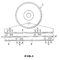
- a pre-recorded region 5 in which a incumferentially extending pattern of projections and recesses is previously formed by pits 4 and a data recording region 6 in which the magneto-optical recording is performed are arranged alternately each at a equal pitch in each land region 3 defined between spirally extending pre-grooves 2 on a magneto-optical disk 1 used as the recording medium in the above disk recording apparatus.
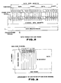
- information data of each processing unit or frame are formed by 33 symbols (264 bits) made up of 24 symbols (12 words) each composed of eight bits, each four symbols of error correction codes P and Q and a symbol as a sub-code for control or user data.
- the data bit of each frame is subjected to a so-called eight to fourteen modulation (EFM) so that the eight bit data of each symbol are converted into a 14-bit pattern to produce 14 x 33 bits or 33 symbols, to which 24-bit sync signals are annexed.
- EFM eight to fourteen modulation
- the frame sync signals and the sub-code among the 588 channel bits making up each frame are recorded in advance as a pattern of projections and recesses on the pre-recorded region 5 by molding and the absolute time or absolute address information from the start position of the data record region 6 is afforded by the Q-channel of the aforementioned sub-code.
- the present Applicant has already proposed a disk recording apparatus wherein the track jump is detected during the recording operation and, on occurrence of a track jump, the laser power of the optical head is lowered to the reproducing level, and then control the optical head to jump tracks to the desired track operation is resumed on the desired track to prevent the information from being recorded in other than the desired track, as shown for example in PCT/JP88/00196.
- the present invention has been made in view of the foregoing and is aimed to provide a disk recording apparatus wherein, even when abnormal conditions such as incorrect focussing servo or track jump should occur in the optical head during data recording, record data loss may be avoided in advance to permit data to be recorded correctly.
- the present invention provides a disk recording apparatus in which predetermined input data are recorded on a disk-like recording medium on the recording track of which predetermined absolute address information is recorded in advance, comprising input storage control means for sequentially storing said input data for every predetermined recording unit, reading out said input data from given position for each of said predetermined recording unit and transmitting the read-out data to recording means, and abnormal condition detection and control means permanently monitoring said absolute address information on said recording track, detecting the abnormal condition based on said absolute address information, calculating, on occurrence of said abnormal condition, the return time required for said recording means to return to the leading position of said recording unit that is being recorded on said recording track and controlling and recording the reading position of said input memory control means in advance by the number of recording units that corresponds to the calculated result.
- the input data are sequentially recorded by input memory control means for every predetermined storage unit and read out from an arbitrary position of the predetermined recording unit so as to be recorded for every predetermined recording unit or the recording track by recording means, an abnormal condition of the recording means is monitored in abnormal condition detection means with the use of the absolute address information obtained from the recording track during recording, the return time required for the recording means to return t'o the leading position of the recording unit during recording is calculated on occurrence of the abnormal condition and the read-out position of the input memory control means is controlled and recorded in advance by the number of the recording units corresponding to the calculated results, whereby the disk recording apparatus may be easily realized in which data may be recorded correctly with prevention of vanishing of the recorded data.
- Fig. 1 is a diagrammatic view of a recording format of a CD system magneto-optical disk
- Fig. 2 is a diagrammatic view showing the data format for one frame of data recorded on the mageto-optical disk
- Fig. 3 is a diagrammatic view showing the arrangement of one block of sub-code channels recorded on the magneto-optical disk.
- Fig. 4 is a block diagram showing an embodiment of the disk recording apparatus according to the present invention
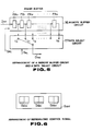
- Fig. 5 is a diagrammatic view showing the arrangement of a memory buffer circuit and a data select circuit in the above embodiment
- Fig. 6 is a diagrammatic view showing the arrangement of reproducing control signals in the above embodiment
- Fig. 7 is a flowchart showing the recording control program.
- FIG. 4 10 designates in general a magneto-optical disk recording apparatus of the present invention.
- Input audio signals AD IN are converted into digital data DG AD in an analog to digital converting circuit 13 via a low pass filter 12 so as to be transmitted to a first input terminal 14A of an input select circuit 14.
- Input digital data DS IN are entered directly at a second input terminal 14B of the input select circuit 14 and switching is made between the first input terminal 14A and the second input terminal 14B based on an input select signal S IN applied to a control terminal of the input select circuit 14 from a control circuit 15 which is made of a computer, in such a manner that a selected one of the two input digital data DG AD and DG IN is transmitted as digital data D IN to an encoding circuit 18 via a memory buffer circuit 16 and a data select circuit 17.
- the memory buffer circuit 16 is formed by an N-number of series connected frame buffers FB 0 , FB 1 , FB 2 , ... , FB N , with each frame having a storage capacity of data corresponding to one unit when digital data D IN are recorded on the recording track, herein to 98 frames or one large frame in the aforementioned CD standard, and is designed to divide the input digital data D IN at the interval of one frame at the timing of frame clock signals S FC afforded from the control circuit 15.
- a buffer memory of the first-in first-out (FIFO) type random access memory (RAM) is used as each of the frame buffer memories FB O , FB 1 , FB 2 , ..., F B N .
- the digital data transmitted from each of the frame buffers FB 0 , FB 1 , FB 1 , FB 2 , ... , FBN making up the memory buffer circuit 16 are entered to the frame buffers FB 1 , FB 2 , ... , FB N , at the timing of the frame clock signals S FC , while being transmitted to the input terminals t 0 , t 1 , t 21 ... , t N of the data select circuit 17.
- the data select circuit 17 is formed by, for example, an analog switch, and, based on data select signal S SL afforded from the control circuit 15, selects one of the input terminals t 0 , t1, t 2 , ... , t N , so that, with the first digital data D IN1 entered to the memory buffer circuit 16, digital data a predetermined time in advance in terms of the units of the aforementioned frame clock signal S FC are transmitted as digital data D IN2 to the next following encoding circuit 18.
- the encoding circuit 18 encodes the digital data D IN2 entered thereto via the data select circuit 17 and the encoded data are modulated in accordance with a predetermined modulation system at the next following modulating circuit 19.
- the modulated encoded data are supplied to a coil section 20 where a magnetic field H switched in accordance with the digital data D IN is applied to the magneto-optical disk 21 that is rotated about a spindle O as center as indicated by the arrow mark a.
- the optical head 22 On the lower surface of the magneto-optical disk 21 and in register with the coil section 20, there is arranged the optical head 22 for irradiating the recording laser output on a predetermined one of the recording tracks, such that the digital data D IN may be recorded by the coil section 20 and the optical head 22 on the magneto-optical disk 21 in accordance with the magnetic field modulation recording system.
- the optical head 22 has a focussing servo circuit and a tracking servo circuit in its interior and is adapted to be slid in a direction transverse to the recording tracks on the magneto-optical disk 21 by an optical head drive circuit 23 controlled on the basis of the drive signal S DV supplied from the control circuit 15.
- control signals S CNT such as the absolute time or absolute address information from the leading end of the recording track, are recorded as the sub-code in the above described standard for the compact disk on the recording track of the magneto-optical disk 21 by so-called groove wobbling, that is, vibration of the groove of the recording track in a direction radially of the disk.
- the control signals S CNT recorded by the above described groove wobbling can be taken out as the difference of the detected outputs by a detector divided in two along the track direction, that is, as the push-pull signals, since the return light of the light spot from the optical head 22 scanning the wobbled groove is diffracted by the wobbled groove to be modulated in the light intensity on the detector of the optical head 22.
- the arrangement is so made that, when recording the digital data D IN' the return light obtained at the magneto-optical disk 21 is received by the optical head 22 and supplied as the reproducing signal RF 1 to the decoding circuit 25 via a reproducing amplifier 24.
- the decoding circuit 25 converts the reproducing signal RF 1 into digital data D OUT and transmits the digital data to an output select circuit 26, while extracting a reproducing control signal S CNT from the reproducing signal RF 1 and transmitting the signal RF 1 to the control circuit 15.
- the reproducing control signal S CNT is associated with each frame of the digital data to be recorded and is composed of a minute data D MIN , a second data D SEC and a frame D FRM , each consisting of eight bits, by way of an example, and is designed to represent as a whole a position on the recording track on the magneto-optical disk 21.
- the output select circuit 26 On the basis of the output select signal S OUT supplied from the control circuit 15, the output select circuit 26 selectively outputs the input digital data D OUT to a first output terminal 26A or a second output terminal 26B.
- the digital data D OUT outputted via first output terminal 26A of the output select circuit 26 are converted via a digital to analog converter 28 into analog data which are outputted as output analog data AD OUT via a low pass filter 29.
- the digital data D OUT outputted via the second output terminal 26B of the output select circuit 26 are outputted directly as the output digital data D OUT .
- an operating section 27 having a recording start key 27A and a stop key 27B, arranged as the push-pull switch, is connected to the control circuit 15.
- the control circuit 15 starts the recording operation of predetermined data by executing the record control program shown in Fig. 7 at the timing of entry of an operation control signal S PL indicating that actuation of the recording start key 27A of the operating section 27 has been made, and performs a control operation in such a manner as to prevent the recorded data from vanishing even when an abnormal condition such as incorrect focussing servo control or track jump should occur in the optical head 22 during data recording.
- control circuit 15 After initiating the control operation by the record control program at a first step SP1, the control circuit 15 sends a data select signal S SL selecting the leading input terminal to to the data select circuit 17 at the next second step SP2 to start the recording operation at the next third step SP3.
- the input digital data D IN are divided at the rate of clocks at the frame interval based on the frame clock signals S FC so as to be transmitted from the leading frame buffer FB O to the data select circuit 17 and recorded on the recording track on the magneto-optical disk 21.
- the digital data D IN stored in the leading frame buffer FB O are sequentially stored in the subsequent frame buffers FB 1 , FB 2 , ... , FB N , at the timing of the frame clock signals S FC .
- the control circuit 15 when proceeds to the fourth step SP4 to monitor the continuity of the recording track on the magneto-optical disk 21 on the basis of the reproducing control signal S CNT supplied from the decoding circuit 25 to make a decision, based on the results of monitoring, as to whether an abnormal condition such as incorrect focussing servo control or track jump has occurred.
- control circuit 15 proceeds to the next fifth step SP5 and decides to whether an operation control signal S PL indicating that actuation of the stop key 27B is inputted.
- the control circuit 15 When a negative decision that is, a decision to the effect that the recording operation should be continued, is obtained at the above fifth step SP5, the control circuit 15 reverts to the fourth step SP4 to repeat a loop of the steps SP4 and SP5 to continue the recording operation until the stop key 27B is actuated by the user, whilst the control circuit monitors the continuity of the recording track on the magneto-optical disk 21.
- the control circuit 15 proceeds to the sixth step SP6 to control the optical head 22 to cause it to issue a reproducing laser output to interrupt the recording operation.
- the control circuit 15 stores the time data on the recording track of a frame in which recording interruption has occurred during recording in the first storage area P o in the inside thereof.
- control circuit 15 supplies a drive signal S DV , such as track jump, to the optical head drive circuit 23 to return the beam spot from the optical head 22 to the leading position of the frame where the recording interruption has occurred.
- control circuit 15 stores the current time in the second storage area P 1 in the inside thereof.
- the control circuit 15 calculates, using the respective time data stored in the first storage area P o and in the second storage area P 1 , the return time required since the occurence of the abnormal condition until the beam stop from the optical head 22 is returned to the leading end of the frame where recording interruption has occurred.
- the control circuit 15 sends a data select signal S SL to select that one of the input terminal t 1 , t2, ... , tN which is in advance by the number of the frames corresponding to the calculated results to the data select circuit 17.
- control circuit 15 controls the optical head 22 to cause it to issue the recording laser output to remuse the recording operation to return to the loop of the aforementioned fourth step SP4 and fifth step SP5.
- control circuit 15 executes the aforementioned sixth to twelfth steps SP6, SP7, SP8, SP9, SP10, SP11 and SP12, in such a manner that, when an abnormal condition such as incorrect focussing servo control or track jump of the optical head 22 has occurred in the magneto-optical disk 21, the control circuit causes the optical head 22 to be returend to a position on the magneto-optical disk 21 corresponding to the leading end of the frame where the abnormal condition has occurred, while the control circuit remuses the recording operation on the magneto-optical disk 21 from that one of the frame buffers FB, FB2, ... , FB N which is in advance by the number of the frames corresponding to the time involved during this procedure, so that recording may be made with data loss even on occurrence of an abnormal condition.
- an abnormal condition such as incorrect focussing servo control or track jump of the optical head 22 has occurred in the magneto-optical disk 21
- the control circuit causes the optical head 22 to be returend to a position on
- the control circuit 15 proceeds to the next thirteenth step SP13 and causes, when the data select circuit 17 selects the frame buffers FB1, FB2, ... , FB N other than the leading frame buffer FB O , the digital data D IN stored in the predetermined frames FB O , FB 1 , FB 2 , ... , FB N to be stored on the magneto-optical disk 21.
- the control circuit 15 then causes the recording operation to be terminated at the next fourteenth step SP14 and terminates the recording control program at the next fifteenth step SP15.
- a series connection of plural frame buffers is used as the memory buffer circuit, and an analog switch type circuit is used as the data select circuit.
- the present invention is not limited thereto and the effect similar to that of the illustrative embodiment may be achieved with the use of other types of circuits, such as the memory circuit in which the write and read-out addresses may be controlled in a ring-like manner.
- the absolute address information is not limited thereto, but may also be address numbers, as an example, while, as the recording method, recording pits may be formed on the recording tracks, or recording may be made by groove wobbling. In sum, the effect similar to that described in the above illustrative embodiment may be realized if the absolute address information such as the time data or address number could be reproduced from the recording track.
Landscapes
- Engineering & Computer Science (AREA)
- Signal Processing (AREA)
- Multimedia (AREA)
- Signal Processing For Digital Recording And Reproducing (AREA)
- Indexing, Searching, Synchronizing, And The Amount Of Synchronization Travel Of Record Carriers (AREA)
- Optical Record Carriers And Manufacture Thereof (AREA)
- Magnetic Record Carriers (AREA)
- Supporting Of Heads In Record-Carrier Devices (AREA)
Abstract
Description
- This invention relates to a disk recording apparatus in which continuous input data such as musical signals are recorded on a disk-like recording medium on the recording tracks of which the predetermined absolute address information is recorded in advance. It is preferably applied to a recordable optical disk apparatus, such as the constant linear velocity (CLV) type write once (WO) type or erasable type optical disk apparatus.
- The present Applicant has already proposed a disk recording apparatus according to which the information is recorded in a data format standardized in a compact disk (CD), using a recordable disk, such as a magneto-optical disk, having a vertical magnetization film exhibiting magneto-optical effect as the magnetic recording layer, as shown for example in PCT/JP87/00764.
- Referring to a diagrammatic view of Fig. 1, a
pre-recorded region 5 in which a incumferentially extending pattern of projections and recesses is previously formed bypits 4 and adata recording region 6 in which the magneto-optical recording is performed are arranged alternately each at a equal pitch in eachland region 3 defined between spirally extending pre-grooves 2 on a magneto-optical disk 1 used as the recording medium in the above disk recording apparatus. - In the data format, standardized in the compact disk (CD), information data of each processing unit or frame are formed by 33 symbols (264 bits) made up of 24 symbols (12 words) each composed of eight bits, each four symbols of error correction codes P and Q and a symbol as a sub-code for control or user data. The data bit of each frame is subjected to a so-called eight to fourteen modulation (EFM) so that the eight bit data of each symbol are converted into a 14-bit pattern to produce 14 x 33 bits or 33 symbols, to which 24-bit sync signals are annexed. There merging bits each are placed between adjacent symbols to produce 588 channel bits which make up one frame shown in Fig. 2. The eight bits of the one symbol annexed as the aforementioned control data or user data from sub-code channels P, Q, R, S, T, U, V and W for constituting a data block or a large frame composed of 98 symbols corresponding to 98 frames, as shown in Fig. 3. Meanwhile, the two symbols at the leading part of the block are dedicated to sync patterns So and S1 for demarcating the boundary of this data block.
- In the above described magneto-optical disk 1, the frame sync signals and the sub-code among the 588 channel bits making up each frame are recorded in advance as a pattern of projections and recesses on the
pre-recorded region 5 by molding and the absolute time or absolute address information from the start position of thedata record region 6 is afforded by the Q-channel of the aforementioned sub-code. - In the above described disk recording apparatus, making use of the magneto-optical disk 1, data such as play information and parity are photomagnetically recorded on the
data record region 6, while the disk rotation control is performed at a CLV or constant linear velocity on the basis of the reproducing output from thepre-recorded region 5 of the disk 1 and tracking servo as well as focusing servo is applied to the optical head. - In the above described disk recording apparatus, when the servo for the optical head is disturbed by some perturbation or malfunction such as vibration or noises in the power source to give rise to abnormal conditions such as incorrect focussing servo control or track jumps, interrupted portions are produced in the data recorded on the magneto-optical disk at the time point of occurrence of these abnormal conditions.
- The present Applicant has already proposed a disk recording apparatus wherein the track jump is detected during the recording operation and, on occurrence of a track jump, the laser power of the optical head is lowered to the reproducing level, and then control the optical head to jump tracks to the desired track operation is resumed on the desired track to prevent the information from being recorded in other than the desired track, as shown for example in PCT/JP88/00196.
- Meanwhile, when such interruption of the record data should occur during the time the disk recording apparatus is used as the computer terminal, it is possible to re-read the record data by the communication exchange procedure with the host computer to make re-recording from the leading end of the interrupted portion.
- It is possible in this manner to lower the laser power of the optical head to the reproducing level, and to perform the track jump control to cause the recording operation to be resumed at the desired track to prevent the information from being erroneously recorded in other than the desired track. However, when recording continuous data on a real time basis, as in live recording of musical performance, the interrupted portion cannot actually be recovered. Even supposing that the optical head is returned immediately to the original recording track, the musical performance data is lost for the time interval that has elapsed during control of the track jump. Thus there is necessarily the risk that the listener cannot but feel disagreeable on account of occurrence of the interrupted portion during the musical performance at the time of reproduction.
- The present invention has been made in view of the foregoing and is aimed to provide a disk recording apparatus wherein, even when abnormal conditions such as incorrect focussing servo or track jump should occur in the optical head during data recording, record data loss may be avoided in advance to permit data to be recorded correctly.
- For accomplishing the above object, the present invention provides a disk recording apparatus in which predetermined input data are recorded on a disk-like recording medium on the recording track of which predetermined absolute address information is recorded in advance, comprising input storage control means for sequentially storing said input data for every predetermined recording unit, reading out said input data from given position for each of said predetermined recording unit and transmitting the read-out data to recording means, and abnormal condition detection and control means permanently monitoring said absolute address information on said recording track, detecting the abnormal condition based on said absolute address information, calculating, on occurrence of said abnormal condition, the return time required for said recording means to return to the leading position of said recording unit that is being recorded on said recording track and controlling and recording the reading position of said input memory control means in advance by the number of recording units that corresponds to the calculated result.
- According to the present invention, the input data are sequentially recorded by input memory control means for every predetermined storage unit and read out from an arbitrary position of the predetermined recording unit so as to be recorded for every predetermined recording unit or the recording track by recording means, an abnormal condition of the recording means is monitored in abnormal condition detection means with the use of the absolute address information obtained from the recording track during recording, the return time required for the recording means to return t'o the leading position of the recording unit during recording is calculated on occurrence of the abnormal condition and the read-out position of the input memory control means is controlled and recorded in advance by the number of the recording units corresponding to the calculated results, whereby the disk recording apparatus may be easily realized in which data may be recorded correctly with prevention of vanishing of the recorded data.
- Fig. 1 is a diagrammatic view of a recording format of a CD system magneto-optical disk; Fig. 2 is a diagrammatic view showing the data format for one frame of data recorded on the mageto-optical disk; Fig. 3 is a diagrammatic view showing the arrangement of one block of sub-code channels recorded on the magneto-optical disk.
- Fig. 4 is a block diagram showing an embodiment of the disk recording apparatus according to the present invention; Fig. 5 is a diagrammatic view showing the arrangement of a memory buffer circuit and a data select circuit in the above embodiment; Fig. 6 is a diagrammatic view showing the arrangement of reproducing control signals in the above embodiment; and Fig. 7 is a flowchart showing the recording control program.
- An embodiment of the present invention will be hereinafter explained by referring to the drawings.
- In Fig. 4, 10 designates in general a magneto-optical disk recording apparatus of the present invention. Input audio signals ADIN are converted into digital data DGAD in an analog to
digital converting circuit 13 via alow pass filter 12 so as to be transmitted to afirst input terminal 14A of an inputselect circuit 14. - Input digital data DSIN are entered directly at a
second input terminal 14B of the inputselect circuit 14 and switching is made between thefirst input terminal 14A and thesecond input terminal 14B based on an input select signal SIN applied to a control terminal of the inputselect circuit 14 from a control circuit 15 which is made of a computer, in such a manner that a selected one of the two input digital data DGAD and DGIN is transmitted as digital data DIN to anencoding circuit 18 via amemory buffer circuit 16 and a dataselect circuit 17. - As shown in Fig. 5, the
memory buffer circuit 16 is formed by an N-number of series connected frame buffers FB0, FB1, FB2, ... , FBN, with each frame having a storage capacity of data corresponding to one unit when digital data DIN are recorded on the recording track, herein to 98 frames or one large frame in the aforementioned CD standard, and is designed to divide the input digital data DIN at the interval of one frame at the timing of frame clock signals SFC afforded from the control circuit 15. A buffer memory of the first-in first-out (FIFO) type random access memory (RAM) is used as each of the frame buffer memories FBO, FB1, FB2, ..., FBN. - The digital data transmitted from each of the frame buffers FB0, FB1, FB1, FB2, ... , FBN making up the
memory buffer circuit 16 are entered to the frame buffers FB1, FB2, ... , FBN, at the timing of the frame clock signals SFC, while being transmitted to the input terminals t0, t1 , t21 ... , tN of the dataselect circuit 17. - The data
select circuit 17 is formed by, for example, an analog switch, and, based on data select signal SSL afforded from the control circuit 15, selects one of the input terminals t 0, t1, t2, ... , tN, so that, with the first digital data DIN1 entered to thememory buffer circuit 16, digital data a predetermined time in advance in terms of the units of the aforementioned frame clock signal SFC are transmitted as digital data DIN2 to the next followingencoding circuit 18. - The
encoding circuit 18 encodes the digital data DIN2 entered thereto via the dataselect circuit 17 and the encoded data are modulated in accordance with a predetermined modulation system at the next following modulatingcircuit 19. The modulated encoded data are supplied to acoil section 20 where a magnetic field H switched in accordance with the digital data DIN is applied to the magneto-optical disk 21 that is rotated about a spindle O as center as indicated by the arrow mark a. - On the lower surface of the magneto-
optical disk 21 and in register with thecoil section 20, there is arranged theoptical head 22 for irradiating the recording laser output on a predetermined one of the recording tracks, such that the digital data DIN may be recorded by thecoil section 20 and theoptical head 22 on the magneto-optical disk 21 in accordance with the magnetic field modulation recording system. - Meanwhile, the
optical head 22 has a focussing servo circuit and a tracking servo circuit in its interior and is adapted to be slid in a direction transverse to the recording tracks on the magneto-optical disk 21 by an opticalhead drive circuit 23 controlled on the basis of the drive signal SDV supplied from the control circuit 15. - In the illustrative embodiment, control signals SCNT, such as the absolute time or absolute address information from the leading end of the recording track, are recorded as the sub-code in the above described standard for the compact disk on the recording track of the magneto-
optical disk 21 by so-called groove wobbling, that is, vibration of the groove of the recording track in a direction radially of the disk. The control signals SCNT recorded by the above described groove wobbling can be taken out as the difference of the detected outputs by a detector divided in two along the track direction, that is, as the push-pull signals, since the return light of the light spot from theoptical head 22 scanning the wobbled groove is diffracted by the wobbled groove to be modulated in the light intensity on the detector of theoptical head 22. - The arrangement is so made that, when recording the digital data DIN' the return light obtained at the magneto-
optical disk 21 is received by theoptical head 22 and supplied as the reproducing signal RF1 to thedecoding circuit 25 via a reproducingamplifier 24. - The
decoding circuit 25 converts the reproducing signal RF1 into digital data DOUT and transmits the digital data to an outputselect circuit 26, while extracting a reproducing control signal SCNT from the reproducing signal RF1 and transmitting the signal RF1 to the control circuit 15. - As shown in Fig. 6, the reproducing control signal SCNT is associated with each frame of the digital data to be recorded and is composed of a minute data DMIN, a second data DSEC and a frame DFRM, each consisting of eight bits, by way of an example, and is designed to represent as a whole a position on the recording track on the magneto-
optical disk 21. - On the basis of the output select signal SOUT supplied from the control circuit 15, the output
select circuit 26 selectively outputs the input digital data DOUT to afirst output terminal 26A or asecond output terminal 26B. - The digital data DOUT outputted via
first output terminal 26A of the outputselect circuit 26 are converted via a digital toanalog converter 28 into analog data which are outputted as output analog data ADOUT via alow pass filter 29. The digital data DOUT outputted via thesecond output terminal 26B of the outputselect circuit 26 are outputted directly as the output digital data DOUT. - It is noted that an
operating section 27 having arecording start key 27A and astop key 27B, arranged as the push-pull switch, is connected to the control circuit 15. - The control circuit 15 starts the recording operation of predetermined data by executing the record control program shown in Fig. 7 at the timing of entry of an operation control signal SPL indicating that actuation of the
recording start key 27A of theoperating section 27 has been made, and performs a control operation in such a manner as to prevent the recorded data from vanishing even when an abnormal condition such as incorrect focussing servo control or track jump should occur in theoptical head 22 during data recording. - After initiating the control operation by the record control program at a first step SP1, the control circuit 15 sends a data select signal SSL selecting the leading input terminal to to the data
select circuit 17 at the next second step SP2 to start the recording operation at the next third step SP3. - At this time, the input digital data DIN are divided at the rate of clocks at the frame interval based on the frame clock signals SFC so as to be transmitted from the leading frame buffer FBO to the data
select circuit 17 and recorded on the recording track on the magneto-optical disk 21. In practice, the digital data DIN stored in the leading frame buffer FBO are sequentially stored in the subsequent frame buffers FB1 , FB2, ... , FBN, at the timing of the frame clock signals S FC. - The control circuit 15 when proceeds to the fourth step SP4 to monitor the continuity of the recording track on the magneto-
optical disk 21 on the basis of the reproducing control signal SCNT supplied from thedecoding circuit 25 to make a decision, based on the results of monitoring, as to whether an abnormal condition such as incorrect focussing servo control or track jump has occurred. - When a negative decision is abtained at the fourth step SP4, the control circuit 15 proceeds to the next fifth step SP5 and decides to whether an operation control signal SPL indicating that actuation of the
stop key 27B is inputted. - When a negative decision that is, a decision to the effect that the recording operation should be continued, is obtained at the above fifth step SP5, the control circuit 15 reverts to the fourth step SP4 to repeat a loop of the steps SP4 and SP5 to continue the recording operation until the
stop key 27B is actuated by the user, whilst the control circuit monitors the continuity of the recording track on the magneto-optical disk 21. When an affirmative result indicating that an abnormal condition such as incorrect focussing servo control or track jump has occurred is produced in this state in the fourth step SP4, the control circuit 15 proceeds to the sixth step SP6 to control theoptical head 22 to cause it to issue a reproducing laser output to interrupt the recording operation. In the next seventh step SP7, the control circuit 15 stores the time data on the recording track of a frame in which recording interruption has occurred during recording in the first storage area Po in the inside thereof. - In the eighth step SP8, the control circuit 15 supplies a drive signal SDV, such as track jump, to the optical
head drive circuit 23 to return the beam spot from theoptical head 22 to the leading position of the frame where the recording interruption has occurred. In the next ninth step SP9, the control circuit 15 stores the current time in the second storage area P1 in the inside thereof. - In the next tenth step SP10, the control circuit 15 calculates, using the respective time data stored in the first storage area Po and in the second storage area P1, the return time required since the occurence of the abnormal condition until the beam stop from the
optical head 22 is returned to the leading end of the frame where recording interruption has occurred. In the next eleventh step SP11, the control circuit 15 sends a data select signal SSL to select that one of the input terminal t1 , t2, ... , tN which is in advance by the number of the frames corresponding to the calculated results to the data selectcircuit 17. - In the next twelfth step SP12, the control circuit 15 controls the
optical head 22 to cause it to issue the recording laser output to remuse the recording operation to return to the loop of the aforementioned fourth step SP4 and fifth step SP5. - It will be appreciated from the foregoing that the control circuit 15 executes the aforementioned sixth to twelfth steps SP6, SP7, SP8, SP9, SP10, SP11 and SP12, in such a manner that, when an abnormal condition such as incorrect focussing servo control or track jump of the
optical head 22 has occurred in the magneto-optical disk 21, the control circuit causes theoptical head 22 to be returend to a position on the magneto-optical disk 21 corresponding to the leading end of the frame where the abnormal condition has occurred, while the control circuit remuses the recording operation on the magneto-optical disk 21 from that one of the frame buffers FB, FB2, ... , FBN which is in advance by the number of the frames corresponding to the time involved during this procedure, so that recording may be made with data loss even on occurrence of an abnormal condition. - When an affirmative result indicating that the stop key 17B has been actuated is produced at the fifth step SP5, the control circuit 15 proceeds to the next thirteenth step SP13 and causes, when the data select
circuit 17 selects the frame buffers FB1, FB2, ... , FBN other than the leading frame buffer FBO, the digital data DIN stored in the predetermined frames FBO, FB1 , FB2, ... , FBN to be stored on the magneto-optical disk 21. The control circuit 15 then causes the recording operation to be terminated at the next fourteenth step SP14 and terminates the recording control program at the next fifteenth step SP15. - In the above arrangement, there may be realized a magneto-optical disk recording apparatus in which, even when an abnormal condition such as incorrect focussing servo control or track jump should occur in the optical head during data recording, data recording may be made correctly with prevention of vanishing of the recording data.
- In the above described illustrative embodiment, a series connection of plural frame buffers is used as the memory buffer circuit, and an analog switch type circuit is used as the data select circuit. However, the present invention is not limited thereto and the effect similar to that of the illustrative embodiment may be achieved with the use of other types of circuits, such as the memory circuit in which the write and read-out addresses may be controlled in a ring-like manner.
- Although the magneto-optical disk in which the absolute time information from the leading end is recorded thereon by land wobbling is used in the illustrative embodiment as the magneto-optical disk of the present invention, the absolute address information is not limited thereto, but may also be address numbers, as an example, while, as the recording method, recording pits may be formed on the recording tracks, or recording may be made by groove wobbling. In sum, the effect similar to that described in the above illustrative embodiment may be realized if the absolute address information such as the time data or address number could be reproduced from the recording track.
- In addition, although the description has been made in the illustrative embodiment of the case in which the recording apparatus of the present invention is applied to the compact disk type magneto-optical disk apparatus, the present invention is not limited thereto, but may be extensively applied to other types of the recording apparatus such as optical or magnetic disk.
Claims (8)
- (1) A disk recording apparatus in which predetermined input data are recorded on a disk-like recording medium on a recording track of which predetermined absolute address information is recorded in advance, comprising input memory control menas for sequentially storing said input data for every predetermined recording unit, reading out said input data from a given position for each of said predetermined recording units and transmitting the read-out data to recording means, and abnormal condition detection and control means permanently monitoring said absolute address informationon said recording track, detecting the abnormal condition based on said absolute address information, calculating, on occurrence of said abnormal condition, the return time required for said recording means to return to the leading position of said recording unit that is being recorded on said recording track, and controlling and recording the reading position of said inpout memory control means in advance by the number of recording units that corresponds to the calculated result.
- (2) The disk recording apparatus according to claim 1 characterized in that said absolute address information is recorded in advance on the recording track as control signals for every predetermined recording unit and in that said abnormal condition detection and control means detects the abnormal condition of the recording operation based on reproducing control signals from the recording track.
- (3) The disk recording apparatus according to claim 2 characterized in that the input data are stored for every predetermined recording unit in accordance with a magnetic field modulation system on the magneto-optical recording medium on which said control signals are recorded in advance as the wobbling information.
- (4) The disk recording apparatus according to claim 2 characterized in that said control signals are reproduced by a one-beam optical head from said magneto-optical recording medium and in the said input data are recorded by magnetic field modulation on said magneto-optical recording medium.
- (5) The disk recording apparatus according to claim 1 comprising an optical head scanning the recording track of the disk-like recording medium by a light beam to record or reproduce data, said abnormal condition detection and control means performing a control operation of switching the laser power of said optical head to the reproducing level on detection of an abnormal condition of the recording operation.
- (6) The disk recording apparatus according to claim 1 wherein said input memory control means includes a first-in first-out memory for storing the input data for every prodetermined recording unit.
- (7) The disk recording apparatus according to claim 6 wherein the recording unit of the input data is one frame.
- (8) The disk recording apparatus according to claim 7 characterized the input data are read out from said first-in first-out memory via a data select circuit constituted by an analog switch.
Applications Claiming Priority (3)
| Application Number | Priority Date | Filing Date | Title |
|---|---|---|---|
| JP301845/87 | 1987-11-30 | ||
| JP62301845A JPH01143080A (en) | 1987-11-30 | 1987-11-30 | Recording device |
| PCT/JP1988/001201 WO1989005509A1 (en) | 1987-11-30 | 1988-11-28 | Disk recording apparatus |
Publications (3)
| Publication Number | Publication Date |
|---|---|
| EP0364586A1 true EP0364586A1 (en) | 1990-04-25 |
| EP0364586A4 EP0364586A4 (en) | 1991-12-04 |
| EP0364586B1 EP0364586B1 (en) | 1994-08-03 |
Family
ID=17901852
Family Applications (1)
| Application Number | Title | Priority Date | Filing Date |
|---|---|---|---|
| EP88910130A Expired - Lifetime EP0364586B1 (en) | 1987-11-30 | 1988-11-28 | Disk recording apparatus |
Country Status (7)
| Country | Link |
|---|---|
| US (1) | US5099464A (en) |
| EP (1) | EP0364586B1 (en) |
| JP (1) | JPH01143080A (en) |
| KR (2) | KR200141095Y1 (en) |
| AT (1) | ATE109586T1 (en) |
| DE (1) | DE3850969T2 (en) |
| WO (1) | WO1989005509A1 (en) |
Cited By (4)
| Publication number | Priority date | Publication date | Assignee | Title |
|---|---|---|---|---|
| EP0474377A1 (en) * | 1990-08-24 | 1992-03-11 | Sony Corporation | Optical disc recording apparatus |
| SG87796A1 (en) * | 1991-05-10 | 2002-04-16 | Discovision Ass | Optical data storage and retrieval system including method for processing data on erasable optical disc |
| US6411580B1 (en) | 1993-01-25 | 2002-06-25 | Noboru Kimura | Storing data on a medium in an optical system |
| RU2280290C2 (en) * | 2000-02-25 | 2006-07-20 | Сони Корпорейшн | Data carrier, recording device and reading device |
Families Citing this family (19)
| Publication number | Priority date | Publication date | Assignee | Title |
|---|---|---|---|---|
| US5517477A (en) * | 1990-01-19 | 1996-05-14 | Sony Corporation | Data recording method and data reproducing apparatus |
| EP0463183B1 (en) * | 1990-01-19 | 2001-09-26 | Sony Corporation | Data recording and reproducing methods |
| JP2843102B2 (en) * | 1990-04-04 | 1999-01-06 | シャープ株式会社 | Information recording / reproducing device |
| JP2995822B2 (en) * | 1990-08-23 | 1999-12-27 | ソニー株式会社 | Recording device and reproducing device for disk-shaped recording medium |
| JP3141241B2 (en) * | 1990-08-24 | 2001-03-05 | ソニー株式会社 | Disk recording device and disk reproducing device |
| JPH04245031A (en) * | 1991-01-30 | 1992-09-01 | Olympus Optical Co Ltd | Optical information recording/reproduction device |
| US5729511A (en) | 1991-02-15 | 1998-03-17 | Discovision Associates | Optical disc system having servo motor and servo error detection assembly operated relative to monitored quad sum signal |
| JP3158474B2 (en) * | 1991-03-28 | 2001-04-23 | ソニー株式会社 | Recording method, disk recording device and disk reproducing device |
| JP2703417B2 (en) * | 1991-04-05 | 1998-01-26 | 富士通株式会社 | Receive buffer |
| JP3024327B2 (en) * | 1991-12-27 | 2000-03-21 | カシオ計算機株式会社 | Digital recorder |
| JP3435712B2 (en) * | 1992-05-22 | 2003-08-11 | ソニー株式会社 | Playing method of disc reproducing apparatus, disc reproducing apparatus |
| KR0138143B1 (en) * | 1992-07-14 | 1998-05-15 | 강진구 | How to Play an Optical Disc Player |
| EP0971352B1 (en) * | 1993-01-21 | 2012-07-04 | Renesas Electronics Corporation | Disk reproducing apparatus |
| JPH06236632A (en) * | 1993-02-09 | 1994-08-23 | Matsushita Electric Ind Co Ltd | Optical disk and optical disk reproducing device |
| JPH06325476A (en) * | 1993-05-14 | 1994-11-25 | Sony Corp | Disk device |
| US5894468A (en) * | 1994-05-06 | 1999-04-13 | Discovision Associates | Data recovery with differentiation and partial integration stages to eliminate noises and DC offset level |
| AU739530B2 (en) * | 1994-05-06 | 2001-10-18 | Discovision Associates | An apparatus for retrieving stored data from an information storage medium |
| US5790495A (en) * | 1994-05-06 | 1998-08-04 | Discovision Associates | Data generator assembly for retrieving stored data by comparing threshold signal with preprocessed signal having DC component |
| KR100413757B1 (en) | 2001-01-22 | 2003-12-31 | 삼성전자주식회사 | Method for detecting the violation of block boundary and apparatus therefor |
Family Cites Families (7)
| Publication number | Priority date | Publication date | Assignee | Title |
|---|---|---|---|---|
| NL187413C (en) * | 1978-03-16 | 1991-09-16 | Philips Nv | REGISTRATION CARRIER, REGISTRATION CARRIER, METHOD FOR REGISTRATION CARRIER BODY AND DEVICE FOR CARRYING OUT A METHOD AND READING A REGISTRATED CARRIER. |
| NL8303565A (en) * | 1983-10-17 | 1985-05-17 | Philips Nv | Apparatus for displaying information from a plate-shaped optically readable record carrier. |
| JPS61139984A (en) * | 1984-12-11 | 1986-06-27 | Nippon Columbia Co Ltd | Optical disk device |
| JPS6292245A (en) * | 1985-10-18 | 1987-04-27 | Canon Inc | optical information recording device |
| NL8601437A (en) * | 1986-06-04 | 1988-01-04 | Philips Nv | SEQUENTIAL BUFFER DEVICE. |
| DE3619258A1 (en) * | 1986-06-07 | 1987-12-10 | Blaupunkt Werke Gmbh | COMPACT DISC (CD) PLAYER |
| JPH06292245A (en) * | 1993-04-01 | 1994-10-18 | Nec Yamagata Ltd | Dtmf reception circuit |
-
1987
- 1987-11-30 JP JP62301845A patent/JPH01143080A/en active Pending
-
1988
- 1988-11-28 EP EP88910130A patent/EP0364586B1/en not_active Expired - Lifetime
- 1988-11-28 AT AT88910130T patent/ATE109586T1/en not_active IP Right Cessation
- 1988-11-28 WO PCT/JP1988/001201 patent/WO1989005509A1/en not_active Ceased
- 1988-11-28 DE DE3850969T patent/DE3850969T2/en not_active Expired - Lifetime
- 1988-11-28 KR KR2019970700013U patent/KR200141095Y1/en not_active Expired - Lifetime
- 1988-11-28 KR KR1019890701420A patent/KR890702199A/en not_active Withdrawn
- 1988-11-28 US US07/391,568 patent/US5099464A/en not_active Expired - Lifetime
Cited By (6)
| Publication number | Priority date | Publication date | Assignee | Title |
|---|---|---|---|---|
| EP0474377A1 (en) * | 1990-08-24 | 1992-03-11 | Sony Corporation | Optical disc recording apparatus |
| US5224087A (en) * | 1990-08-24 | 1993-06-29 | Sony Corporation | Apparatus for recording compressed digital information to an optical disc |
| SG87796A1 (en) * | 1991-05-10 | 2002-04-16 | Discovision Ass | Optical data storage and retrieval system including method for processing data on erasable optical disc |
| US6570839B2 (en) | 1991-05-10 | 2003-05-27 | Discovision Associates | Optical data system and optical disk relating thereto |
| US6411580B1 (en) | 1993-01-25 | 2002-06-25 | Noboru Kimura | Storing data on a medium in an optical system |
| RU2280290C2 (en) * | 2000-02-25 | 2006-07-20 | Сони Корпорейшн | Data carrier, recording device and reading device |
Also Published As
| Publication number | Publication date |
|---|---|
| EP0364586B1 (en) | 1994-08-03 |
| ATE109586T1 (en) | 1994-08-15 |
| DE3850969D1 (en) | 1994-09-08 |
| JPH01143080A (en) | 1989-06-05 |
| WO1989005509A1 (en) | 1989-06-15 |
| KR970700013U (en) | 1997-12-24 |
| DE3850969T2 (en) | 1995-01-19 |
| KR200141095Y1 (en) | 1999-05-01 |
| KR890702199A (en) | 1989-12-23 |
| EP0364586A4 (en) | 1991-12-04 |
| US5099464A (en) | 1992-03-24 |
Similar Documents
| Publication | Publication Date | Title |
|---|---|---|
| US5099464A (en) | Magneto optical disk recording apparatus including a plurality of connected recording unit buffer memories | |
| US5325347A (en) | Data recording method and data reproducing apparatus with contiguous data recording | |
| CA2045052C (en) | Disc recording/reproducing apparatus | |
| US5224087A (en) | Apparatus for recording compressed digital information to an optical disc | |
| US5388093A (en) | Disc recording and/or reproducing apparatus for recording continuous compressed data in plural data regions and disc therefor | |
| RU2199158C2 (en) | Medium for recording program entered in recording medium with first control field for controlling first attribute and second control field for controlling second attribute (alternatives) | |
| US5367510A (en) | Disk recording/reproducing apparatus having the capability of recording an operator designated program sequence | |
| EP0535832B1 (en) | Disc recording/reproducing apparatus and disc | |
| USRE36218E (en) | Disc recording/reproducing apparatus having a servo system capable of successively recording and reproducing tracks on a disc irrespective of turbulence of the servo system due to a disturbance | |
| US5504728A (en) | Method for recording of disk and apparatus for adjusting position of breakpoint of audio data | |
| EP0512821B1 (en) | Disc recording apparatus and disc reproducing apparatus | |
| US5563861A (en) | Optical disc recording apparatus which controls re-recording after a disturbance as a function of the frequency of the detected disturbance | |
| EP0506471A1 (en) | Disk recording and reproduction | |
| EP0347858A2 (en) | Optical disc and recording and reproducing apparatus employing the optical disc | |
| US5553055A (en) | Disc playback method | |
| EP0536764A1 (en) | Disc-shaped recording medium | |
| JP3920666B2 (en) | Data recording control device | |
| US6819642B2 (en) | Data recording device, data reproducing device, and optical disc | |
| JP3405358B2 (en) | Optical disk recording device and optical disk reproducing device | |
| JP2002100051A (en) | disk | |
| JPH06342560A (en) | Digital signal recording/reproducing device | |
| JP2000067520A (en) | Reproduction device and reproduction method |
Legal Events
| Date | Code | Title | Description |
|---|---|---|---|
| PUAI | Public reference made under article 153(3) epc to a published international application that has entered the european phase |
Free format text: ORIGINAL CODE: 0009012 |
|
| 17P | Request for examination filed |
Effective date: 19890729 |
|
| AK | Designated contracting states |
Kind code of ref document: A1 Designated state(s): AT DE FR GB NL |
|
| A4 | Supplementary search report drawn up and despatched |
Effective date: 19911014 |
|
| AK | Designated contracting states |
Kind code of ref document: A4 Designated state(s): AT DE FR GB NL |
|
| 17Q | First examination report despatched |
Effective date: 19930204 |
|
| GRAA | (expected) grant |
Free format text: ORIGINAL CODE: 0009210 |
|
| AK | Designated contracting states |
Kind code of ref document: B1 Designated state(s): AT DE FR GB NL |
|
| REF | Corresponds to: |
Ref document number: 109586 Country of ref document: AT Date of ref document: 19940815 Kind code of ref document: T |
|
| REF | Corresponds to: |
Ref document number: 3850969 Country of ref document: DE Date of ref document: 19940908 |
|
| ET | Fr: translation filed | ||
| PLBE | No opposition filed within time limit |
Free format text: ORIGINAL CODE: 0009261 |
|
| STAA | Information on the status of an ep patent application or granted ep patent |
Free format text: STATUS: NO OPPOSITION FILED WITHIN TIME LIMIT |
|
| 26N | No opposition filed | ||
| REG | Reference to a national code |
Ref country code: GB Ref legal event code: IF02 |
|
| PGFP | Annual fee paid to national office [announced via postgrant information from national office to epo] |
Ref country code: DE Payment date: 20071122 Year of fee payment: 20 Ref country code: NL Payment date: 20071023 Year of fee payment: 20 |
|
| PGFP | Annual fee paid to national office [announced via postgrant information from national office to epo] |
Ref country code: AT Payment date: 20071113 Year of fee payment: 20 |
|
| PGFP | Annual fee paid to national office [announced via postgrant information from national office to epo] |
Ref country code: GB Payment date: 20071128 Year of fee payment: 20 Ref country code: FR Payment date: 20071108 Year of fee payment: 20 |
|
| REG | Reference to a national code |
Ref country code: GB Ref legal event code: PE20 Expiry date: 20081127 |
|
| PG25 | Lapsed in a contracting state [announced via postgrant information from national office to epo] |
Ref country code: NL Free format text: LAPSE BECAUSE OF EXPIRATION OF PROTECTION Effective date: 20081128 |
|
| PG25 | Lapsed in a contracting state [announced via postgrant information from national office to epo] |
Ref country code: GB Free format text: LAPSE BECAUSE OF EXPIRATION OF PROTECTION Effective date: 20081127 |