EP0364599B1 - Procede et dispositif de commande de la pression dans une machine de moulage a injection a alimentation electrique - Google Patents
Procede et dispositif de commande de la pression dans une machine de moulage a injection a alimentation electrique Download PDFInfo
- Publication number
- EP0364599B1 EP0364599B1 EP89903255A EP89903255A EP0364599B1 EP 0364599 B1 EP0364599 B1 EP 0364599B1 EP 89903255 A EP89903255 A EP 89903255A EP 89903255 A EP89903255 A EP 89903255A EP 0364599 B1 EP0364599 B1 EP 0364599B1
- Authority
- EP
- European Patent Office
- Prior art keywords
- pressure
- pressure control
- transition
- limit value
- torque limit
- Prior art date
- Legal status (The legal status is an assumption and is not a legal conclusion. Google has not performed a legal analysis and makes no representation as to the accuracy of the status listed.)
- Revoked
Links
- 238000000034 method Methods 0.000 title claims abstract description 60
- 238000001746 injection moulding Methods 0.000 title claims abstract description 42
- 230000007704 transition Effects 0.000 claims description 93
- 230000008569 process Effects 0.000 claims description 36
- 230000004048 modification Effects 0.000 claims description 30
- 238000012986 modification Methods 0.000 claims description 30
- 230000006870 function Effects 0.000 claims description 9
- 230000014509 gene expression Effects 0.000 claims description 8
- 238000013459 approach Methods 0.000 claims description 6
- 230000008859 change Effects 0.000 claims description 6
- 238000002347 injection Methods 0.000 abstract description 24
- 239000007924 injection Substances 0.000 abstract description 24
- 230000004044 response Effects 0.000 description 9
- 238000010586 diagram Methods 0.000 description 6
- 238000009826 distribution Methods 0.000 description 5
- 238000012545 processing Methods 0.000 description 5
- 230000006866 deterioration Effects 0.000 description 3
- 238000000465 moulding Methods 0.000 description 3
- 230000004043 responsiveness Effects 0.000 description 3
- 238000013479 data entry Methods 0.000 description 2
- 230000007423 decrease Effects 0.000 description 2
- 230000000694 effects Effects 0.000 description 2
- 238000004519 manufacturing process Methods 0.000 description 2
- 238000003860 storage Methods 0.000 description 2
- 239000011347 resin Substances 0.000 description 1
- 229920005989 resin Polymers 0.000 description 1
- 239000000126 substance Substances 0.000 description 1
Images



Classifications
-
- B—PERFORMING OPERATIONS; TRANSPORTING
- B29—WORKING OF PLASTICS; WORKING OF SUBSTANCES IN A PLASTIC STATE IN GENERAL
- B29C—SHAPING OR JOINING OF PLASTICS; SHAPING OF MATERIAL IN A PLASTIC STATE, NOT OTHERWISE PROVIDED FOR; AFTER-TREATMENT OF THE SHAPED PRODUCTS, e.g. REPAIRING
- B29C45/00—Injection moulding, i.e. forcing the required volume of moulding material through a nozzle into a closed mould; Apparatus therefor
- B29C45/17—Component parts, details or accessories; Auxiliary operations
- B29C45/76—Measuring, controlling or regulating
- B29C45/77—Measuring, controlling or regulating of velocity or pressure of moulding material
-
- B—PERFORMING OPERATIONS; TRANSPORTING
- B29—WORKING OF PLASTICS; WORKING OF SUBSTANCES IN A PLASTIC STATE IN GENERAL
- B29C—SHAPING OR JOINING OF PLASTICS; SHAPING OF MATERIAL IN A PLASTIC STATE, NOT OTHERWISE PROVIDED FOR; AFTER-TREATMENT OF THE SHAPED PRODUCTS, e.g. REPAIRING
- B29C45/00—Injection moulding, i.e. forcing the required volume of moulding material through a nozzle into a closed mould; Apparatus therefor
- B29C45/17—Component parts, details or accessories; Auxiliary operations
- B29C45/76—Measuring, controlling or regulating
-
- B—PERFORMING OPERATIONS; TRANSPORTING
- B29—WORKING OF PLASTICS; WORKING OF SUBSTANCES IN A PLASTIC STATE IN GENERAL
- B29C—SHAPING OR JOINING OF PLASTICS; SHAPING OF MATERIAL IN A PLASTIC STATE, NOT OTHERWISE PROVIDED FOR; AFTER-TREATMENT OF THE SHAPED PRODUCTS, e.g. REPAIRING
- B29C45/00—Injection moulding, i.e. forcing the required volume of moulding material through a nozzle into a closed mould; Apparatus therefor
- B29C45/17—Component parts, details or accessories; Auxiliary operations
- B29C45/46—Means for plasticising or homogenising the moulding material or forcing it into the mould
- B29C45/57—Exerting after-pressure on the moulding material
Definitions
- the present invention relates to a method and an apparatus for pressure control, capable of smoothly effecting multi-stage pressure control in a motor-operated injection-molding machine.
- JP-A-62-32019 An example of multi-stage parameter control in an injection molding machine is provided by JP-A-62-32019, wherein injection speed is controlled in stages.
- multi-stage pressure control is performed to produce good-quality moldings.
- a pressure hold process is divided into a plurality of pressure hold stages, and target hold pressures for the individual pressure hold stages are set to values different from one another, so that the hold pressures are subjected to multi-stage control.
- a torque limit value (target hold pressure) for restricting the output torque of a servomotor for axially driving an injection screw is successively changed with the lapse of time from an instant at which pressure hold is started, so that the hold pressure is subjected to open-loop control, as disclosed in JP-A-61-61820.
- the hold pressure is subjected to closed-loop control (see JP-A-62-97818) (feedback control) in accordance with the difference between the torque limit value thus changed in succession and a detected value of the hold pressure actually acting on resin.
- the multi-stage pressure control of the injection-molding machine has a problem such that the actual pressure overshoots or undershoots the target pressure at the time of switching the target pressure, due to various factors, including inertia of the screw, inertia of the servomotor, incompatibility of the response output characteristic of the servomotor, and incompatibility of the control gain of a closed-loop control system.
- the incompatibility of the control gain can be eliminated by adjusting, for example, the proportional, differential, and integral parameters of a PID control section of the control system, without changing the arrangement of the control system. In any control method, however, it is difficult to eliminate unsatisfactory responsiveness attributable to the servomotor or the like.
- the object of the present invention is to provide a method and an apparatus for pressure control of a motor-operated injection-molding machine, with the help of which a multi-stage pressure control pattern of the injection-molding machine, especially a target pressure switching pattern between adjacent pressure control stages, can be made compatible with the response output characteristic of a servomotor mounted on the injection-molding machine, deterioration of the responsiveness due to the inertia of the servomotor and of an operating part of a pressurization apparatus can be restrained, and various modes of multi-stage pressure control can be smoothly effected without mounting a special servomotor on the injection-molding machine or replacing a once mounted servomotor with another servomotor.
- a pressure control method for a motor-operated injection-molding machine in which an operating part of a pressurization apparatus is driven by a servomotor, the pressure control method comprising steps of setting and storing a target pressure for each of a plurality of pressure control stages constituting a pressure control process and being characterized by the steps of
- a pressure control apparatus of an injection-molding machine for restricting the output torque of a servomotor, used to drive an operating part of a pressurization apparatus, to a torque limit value indicative of a target pressure
- the pressure control apparatus comprising: means for setting a torque limit value for each of a plurality of pressure control stages constituting a pressure control process and a respective predetermined switching time in which switching of the target pressures between associated adjacent pressure control stages is to be finished; means for storing the respective torque limit value and the respective predetermined switching time thus set; means for calculating a number of repetitions of modification by dividing the predetermined switching time associated with transition between adjacent pressure control stages by a predetermined pressure control execution period, every time the transition is effected, and for calculating a modification amount by dividing the difference between a torque limit value for a pressure control stage before the transition and a torque limit value for a pressure control stage after the transition by the number of repetitions of modification; means for gradually updating the torque limit value
- a pressure control apparatus of an injection-molding machine for restricting the output torque of a servomotor, used to drive an operating part of a pressurization apparatus, to a torque limit value indicative of a target pressure
- the pressure control apparatus comprising: means for setting a torque limit value for each of a plurality of pressure control stages constituting a pressure control process and a respective predetermined switching time in which switching of the target pressures between associated adjacent pressure control stages is to be finished; means for storing the respective torque limit value and the respective predetermined switching time thus set; means for periodically calculating a respective torque limit value for transition between associated adjacent pressure control stages, every time the transition is effected, in such a manner that the target pressure gradually changes from a target pressure for a pressure control stage before the transition to a target pressure for a pressure control stage after the transition, and that an amount of change of the target pressure at the end of the transition approaches zero, in accordance with a predetermined arithmetic expression including, as parameters, the pre
- the target pressure (torque limit value) is gradually changed from the target pressure for the pressure control stage before the transition to the target pressure for the pressure control stage after the transition within the predetermined switching time, during the transition between the pressure control stages of the pressure control process.
- the resulting pressure control pattern can be made compatible with the response output characteristic of the servomotor mounted on the injection-molding machine, deterioration of the responsiveness due to the inertia of the servomotor and of the operating part of the pressurization apparatus can be restrained, deterioration of the performance for the actual pressure to follow up the target pressure, attributable to the switching of the target pressure during multi-stage pressure control, can be prevented, and the multi-stage pressure control can be smoothly effected, without mounting a special servomotor on the injection-molding machine, so that high-quality, low-priced moldings can be manufactured.
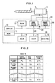
- a motor-operated injection-molding machine to which is applied a multi-stage pressure control method comprises, as pressurization apparatuses, an injection/pressure hold apparatus, a mold clamping apparatus, an ejector (none of which are shown), etc.
- the injection/pressure hold apparatus includes an injection servomotor 1 for axially driving a screw 2 as an operating section and a servomotor (not shown) for screw rotation, and a position detector, e.g., a pulse coder 3, is attached to the servomotor 1.
- the injection-molding machine comprises a control device 10 which has a function as a pressure control device and other conventional control functions.
- the control device 10 comprises an numerical control central processing unit (hereinafter referred to as NCCPU) 11 for controlling the operation of the whole injection-molding machine, pulse distribution processing for servomotors for various axes, etc., and a servo control central processing unit (hereinafter referred to as servo CPU) 12 for controlling the respective speeds and output torques of the servomotors for the individual axes, in accordance with command values from the NCCPU 11 (e.g., the amount of pulse distribution for each axis and a torque limit value for an injection axis).
- NCCPU numerical control central processing unit
- servo CPU servo control central processing unit
- the NCCPU 11 is connected with a ROM 13, a RAM 14, and a manual data input device (hereinafter referred to as CRT/MDI) 15 with a CRT display by means of busses 16.
- the ROM 13 serves to store a control program for managing the whole injection-molding machine, a sequence program for controlling the sequence operation of the injection-molding machine, a program for controlling the servo CPU 12, etc.
- the RAM 14 is adapted to store various parameters, including the maximum injection pressure (target injection pressure at the final stage of an injection process), set individually by means of the CRT/MDI 15, and torque limit values (target hold pressures), pressure hold times, and predetermined switching times for several pressure hold stages of a pressure hold process.
- the servo CPU 12 is connected, through busses 20, with a RAM 17, a speed control circuit 18, and a torque control circuit 19 which, in conjunction with the elements 17 and 18, constitutes a so-called software servo.
- the servo CPU is so arranged that various data, command values from the NCCPU 11, and a program for servo CPU control transferred from the CPU 11 through busses 21 when electric power is turned on are temporarily stored in the RAM 17, and that the speed of the servomotor 1 is controlled in accordance with the amount of pulse distribution from the CPU 11 and a feedback signal from the pulse coder 3, and that the output torque of the servomotor 1 is controlled in accordance with the torque limit value.
- the NCCPU 11 causes the parameters I; P i , T i , and ⁇ T i to be stored in Table TB (Fig. 2) in the RAM 14.
- injection-molding cycle which consists of a series of processes, including mold clamping, injection, pressure hold, metering, mold opening, and product ejection.
- the NCCPU 11 executes the hold pressure control operation, mainly including a torque limit value setting process, at intervals of cycle which is the same as a pulse distribution execution period for the servomotors for various axes, for example, in accordance with the control program shown in Figs. 3 and 4. Namely, at the start of the pressure hold process, the CPU 11 determines whether a value C (indicative of a number of repetitions of update of a torque limit value (mentioned later)) in a modification frequency counter, provided, for example, in the RAM 14, is "0" (Step S1).
- a value C indicative of a number of repetitions of update of a torque limit value (mentioned later)
- a modification frequency counter provided, for example, in the RAM 14, is "0"
- the modification frequency counter is reset to "0" by initialization at the time of power-on operation, so that the counter value at the start of the pressure hold process of the first injection-molding cycle is "0," and the decision in Step S1 is positive. Then, the NCCPU 11 discriminates the present or subsequent pressure hold stage number (i + 1), in accordance with a value i in a pressure hold stage number counter provided, for example, in the RAM 14. This counter is reset at the time of the power-on operation, whereupon the counter value is "0.” Accordingly, the CPU 11 regards the pressure hold stage as a first one, and reads out a predetermined switching time ⁇ T1 (generally, ⁇ T i+1 ) for the first pressure hold stage from Table TB (Step S2).
- ⁇ T1 generally, ⁇ T i+1
- the CPU 11 calculates a required modification frequency (a number of repetitions of modification) n by dividing the switching time ⁇ T1 by a hold pressure control operation execution period ⁇ (Step S3), and determines whether the value i in the pressure hold stage number counter is "0" (Step S4).
- Step S5 a target pressure for the final stage (pressure control stage) of the injection process, e.g., a maximum injection pressure PS (generally, a target pressure for the preceding pressure control stage from which the transition is effected), is set in a first register R (P1) provided, for example, in the RAM 14. Subsequently, a torque limit value P1 (generally, a value P i+1 for the subsequent pressure hold stage to which the transition is effected) for the firsts pressure hold stage is read out from Table TB, and is set in a second register R (P2) provided, for example, in the RAM 14 (Step S6).
- a target pressure for the final stage (pressure control stage) of the injection process e.g., a maximum injection pressure PS (generally, a target pressure for the preceding pressure control stage from which the transition is effected)
- P1 a torque limit value P1 (generally, a value P i+1 for the subsequent pressure hold stage to which the transition is effected) for the firsts
- Step S10 whether the value C in the modification frequency counter is "0" is determined.
- the decision is positive, and the program proceeds to Step S11, whereupon a pressure hold time T1 (generally, T i+1 ) for the first pressure hold stage is read out from Table TB, and is set in a timer TE, thereby starting the timer (Step S12).
- T1 generally, T i+1
- Step S13 the torque limit value setting process for the present hold pressure control operation execution period (pulse distribution period) ends.
- the servo CPU 12 reads out the torque limit value, updated in Step S9, from the RAM 14, and in response to this, causes the torque control circuit 9 to control the output torque of the servomotor 1 to this torque limit value, and applies a target hold pressure (here PS + ⁇ P ( ⁇ P ⁇ 0) ) for the present period to the screw 2.
- a target hold pressure here PS + ⁇ P ( ⁇ P ⁇ 0)
- Step S1 Since the torque limit value is modified during the preceding period, it is concluded in Step S1 that the value C in the modification frequency counter is "0. " Then, the program proceeds to Step S14, whereupon whether the pressure hold time T1 (generally, T i+1 ) set in the timer TE is terminated is determined. Here the decision is negative, so that whether the required modification frequency n is attained by the value C in the modification frequency counter is determined (Step S15). Here the value C is "1,” and the decision in Step S15 is negative, so that the modification amount ⁇ P is added again to the first register R (P1) to effect second modification and updating of the torque limit value (Steps S8 and S9), whereupon the program proceeds to Step S10.
- T1 generally, T i+1
- Step S13 Since the value C is "1," the program proceeds to Step S13 without execution of Steps S11 and S12, whereupon the value C in the modification frequency counter is updated.
- the servo CPU 12 operates so that the hold pressure of PS + 2 ⁇ P is applied to the screw 2 in accordance with the modified torque limit value.
- the NCCPU 11 updates the torque limit value for each period while the program is proceeding from the final stage of the injection process to the first pressure hold stage of the pressure hold process (generally, between adjacent pressure control stages).
- Step S1, S14, and S15 are executed unless the set time of the timer TE is found to be up, and the torque limit value is kept at the value P1 without being modified.
- the servo CPU 12 controls the output torque of the servomotor 1 for the torque limit value P1.
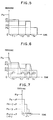
- a torque limit value switching pattern as a function of the parameters PS, P1, ⁇ , and ⁇ T1, shown in the left end portion of Fig. 6 and in Fig. 7, is set so that the servomotor 1 can satisfactorily follow up this changing pattern, in view of the response output characteristic of the motor, and that unsatisfactory follow-up cannot be caused by the inertia of the servomotor 1 and the screw 2.
- the pattern is set so that the hold pressure, produced as a result of deceleration control of the servomotor 1 using the switching time ⁇ T1 as a time constant, can satisfactorily follow up the torque limit value changing pattern.
- Step S3 the required modification frequency n for the second pressure hold stage is calculated (Step S3), and whether the counter value i is "0" is determined (Step S4).
- the decision here is negative, and a torque limit value P2 for the second pressure hold stage is read out from Table TB, and is set in the second register R (P2) (Step S6).
- the NCCPU 11 gradually updates the torque limit value from the value P1 to the value P2 for each period, using the modification amount ⁇ P for the transition from the first pressure hold stage to the second pressure hold stage, while updating the value C in the modification frequency counter.
- the NCCPU 11 starts the timer TE with a pressure hold time T2 for the second pressure hold stage set therein (Steps S8 to S13), and executes only the loop including Step S1, S14, and S15, thereby keeping the torque limit value at the value P2, for the duration of the pressure hold time T2 after the completion of the transition to the second pressure hold stage.
- the servo CPU 12 controls the output torque of the servomotor 1 to the torque limit value gradually updated from the value P1 to the value P2 and then kept at the value P2.
- the program proceeds to the third pressure hold stage, in the manner as aforesaid, and further to the fourth pressure hold stage.
- the torque limit value switching pattern (Fig. 6) for the transition to each of the second to fourth pressure hold stages is set so that the produced hold pressure can satisfactorily follow up the pattern at its leading and trailing edges, and therefore, the produced hold pressure cannot substantially overshoot or undershoot the torque limit value.
- Step S19 the pressure hold stage number counter is reset (Step S19). Also, the subsequent processes, including the metering process, are executed, whereupon one injection-molding cycle is finished. Thereafter, the injection-molding cycle is repeatedly executed in the same manner as aforesaid.
- Figs. 8 to 10 a multi-stage pressure control method according to a second embodiment of the present invention will be described in connection with the hold pressure control of Fig. 5, by way of example.
- the method of this embodiment unlike the method of the foregoing embodiment which uses a target pressure variation pattern indicative of a linear change from the target pressure at the pressure control stage before the transition to that at the control stage after the transition, is designed so that multi-stage pressure control can be more smoothly effected using a pattern such that a change per unit time of the target value immediately before the completion of the transition gradually approaches zero.
- the method of the present embodiment can be executed by means of the apparatus shown in Fig. 1.
- the NCCPU 11 causes Table TB (Fig. 2) to store these parameters.
- the NCCPU 11 sets a value j in the pressure hold stage number counter to "1" (Step S101 of Fig. 8), resets a timer R (t), which indicates the lapse of time t from an instant at which the transition to a new pressure hold stage (first pressure hold stage in this case) is started, to "0,” and then starts the timer (Step S102). Then, the NCCPU 11 discriminates the present or subsequent pressure hold stage number j in accordance with the counter number j .
- the pressure hold stage is regarded as the first one, and the torque limit value P1, pressure hold time T1, and switching time ⁇ T1 for the first pressure hold stage (generally, the parameters P j , T j , and ⁇ T j for the subsequent pressure hold stage) are read out from Table TB of the RAM 14, while the maximum injection pressure PS (generally, a torque limit value P j-1 for the preceding pressure hold stage) is read out from another memory region of the RAM 14 (Step S103).
- the torque limit value P for the present hold pressure control operation execution period is calculated in accordance with a predetermined arithmetic expression for calculating the torque limit value, e.g., the following equation (1) (Step S104).
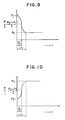
- the value P gradually increases or decreases along a cosine curve, from the former target pressure to the latter target pressure (see Figs. 9 and 10).
- the NCCPU 11 causes the torque limit value storage region of the RAM 17 to store the thus calculated torque limit value P for the present period (Step S105). Meanwhile, the servo CPU 12 reads out the stored value, controls the output torque of the servomotor 1 to the value P, and applies the target hold pressure for the present period to the screw 2.
- Step S106 the NCCPU 11 determines whether the switching time ⁇ T1 (generally, ⁇ T j ) has elapsed from an instant at which the transition is started (Step S106). If the switching time ⁇ T1 is not terminated, the processing of Step S104 is executed to calculate a new torque limit value P, and updates the torque limit value stored in the RAM 14 for the calculated value in Step S105. Processing of a loop including Steps S104 to S106 is periodically executed until the switching time ⁇ T1 terminates.
- the switching time ⁇ T1 generally, ⁇ T j
- the variable t gradually changes, so that the torque limit value periodically calculated according to equation (1) changes in tiers, and in substance, changes smoothly along a cosine curve (torque limit value switching pattern) shown in Fig. 9 or Fig. 10.
- the switching pattern characterized by the control variable ⁇ T j which resembles the pattern shown in Fig. 6, is set so that the servomotor 1 can satisfactorily follow up the pattern, in view of the response output characteristic of the motor, and that unsatisfactory follow-up cannot be caused by the inertia of the servomotor 1 and the screw 2.
- the hold pressure actually applied to the screw 2 which is driven by the servomotor 1, changes smoothly from the value P j-1 to the value P j , and never overshoots or undershoots with respect to the switching pattern.
- Step S106 If it is concluded in Step S106 that the switching time ⁇ T1 is terminated, whether the pressure hold time T1 for the first pressure hold stage is terminated is repeatedly determined (Step S107). In the meantime, the torque limit value is kept at the value P1 obtained upon passage of the switching time ⁇ T1, and the actual hold pressure acting on the screw 2 is controlled to the value P1.
- j 2
- the program proceeds to Step S102, whereupon the hold pressure control for the second pressure hold stage is executed in the aforementioned manner.
- Step S109 the decision in Step S109 is positive, whereupon the hold pressure control is finished.
- the actually produced pressure satisfactorily follows up the target pressure which varies with the lapse of time, so that the multi-stage pressure control can be smoothly effected.
- the hold pressure is subjected to open-loop control in both the embodiments described above, the present invention may be also applied to closed-loop control.
- the torque limit value (target hold pressure) is updated at the initial part of the subsequent pressure hold stage.
- the updating may be performed between the last part of the preceding pressure hold stage and the initial part of the subsequent pressure hold stage.
- the torque limit value is updated using equation (1) which includes the cosine function varying as a function of the lapse of time t from an instant at which the transition starts.
- the torque limit value may be updated using various arithmetic expressions, such as a cubic polynomial expression and a hyperbolic functional equation varying as a function of t , e.g., the following equation (2), in which a torque limit value is given such that a changing amount thereof appearing immediately before or on completion of the transition gradually approaches "0.”
- the present invention is not limited to this.
- the present invention may be also applied to switching of the target injection pressure between adjacent injection pressure control stages and switching from the target pressure for the final stage of the pressure hold process to a target back pressure for the metering process. Also in this case, the aforementioned modifications may be effected.
Landscapes
- Engineering & Computer Science (AREA)
- Manufacturing & Machinery (AREA)
- Mechanical Engineering (AREA)
- Injection Moulding Of Plastics Or The Like (AREA)
Abstract
Claims (17)
- Un procédé de commande de pression pour une machine motorisée de moulage à injection, dans laquelle une partie de fonctionnement (2) d'un appareil de mise sous pression est entraînée par un servomoteur (9), le procédé de commande de pression comprenant le réglage et la mise en mémoire d'une pression de cible (Pn) pour chacune d'un ensemble d'étapes de commande de pression constituant un processus de commande de pression, le procédé étant caractérisé par les opérations consistant à :(a) régler et mettre en mémoire des temps de commutation respectifs déterminés à l'avance (ΔTn) dans lesquels doit être terminée la commutation des pressions de cible (Pn) entre des étapes de commande de pression adjacentes associées,(b) modifier graduellement la pression de cible depuis une pression de cible (Pn) pour une étape de commande de pression avant la transition entre les étapes de commande de pression adjacentes jusqu'à une pression de cible (Pn+1) pour une étape de commande de pression après la transition, pendant le temps compris entre un instant auquel la transition est amenée à démarrer et un instant auquel le temps de commutation déterminé à l'avance (ΔTn) associé à ladite transition s'est écoulé, chaque fois que ladite transition est effectuée ; et(c) commander la pression réelle vers chaque pression de cible correspondante (Pn) mise en mémoire dans ladite opération (a), dans chaque dit stade de commande de pression, et pour commander la pression réelle vers la pression de cible modifiée graduellement obtenue dans ladite opération (b), au cours de chaque dite transition.
- Un procédé de commande de pression selon la revendication 1, comprenant une opération de réglage et de mise en mémoire d'un temps d'exécution (Tn) pour chaque dite étape de commande de pression, et dans lequel une étape de commande de pression ultérieure est introduite lorsque se termine le temps d'exécution pour chaque dite étape de commande de pression.
- Un procédé de commande de pression selon la revendication 1 ou 2, dans lequel ledit processus de commande de pression est un processus de maintien de pression.
- Un procédé de commande de pression selon la revendication 1, 2 ou 3, dans lequel la pression cible est modifiée de manière linéaire, dans ladite opération (b), depuis la pression cible (Pn) pour l'étape de commande de pression avant la transition jusqu'à la pression cible (Pn+1) pour l'étape de commande de pression après la transition.
- Un procédé de commande de pression selon la revendication 1, 2 ou 3, dans lequel ladite pression de cible est modifiée dans ladite opération (b) de telle manière qu'une valeur de modification de ladite pression de cible à la fin de la transition se rapproche de zéro.
- Un procédé de commande de pression selon la revendication 5, dans lequel ladite pression de cible est modifiée dans ladite opération (b) de telle manière qu'une valeur de modification de ladite pression de cible au début de la transition se rapproche de zéro.
- Un procédé de commande de pression selon la revendication 6, dans lequel ladite pression de cible est modifiée dans ladite opération (b) le long d'une courbe déterminée à l'avance qui change de manière monotone depuis la pression de cible (Pn) pour l'étape de commande de pression avant la transition jusqu'à la pression de cible (Pn+1) pour l'étape de commande de pression après la transition.
- Un procédé de commande de pression selon la revendication 7, dans lequel ladite courbe déterminée à l'avance est une courbe en cosinus.
- Un procédé de commande de pression selon la revendication 7, dans lequel ladite courbe déterminée à l'avance est une courbe de type cubique.
- Un appareil de commande de pression d'une machine de moulage par injection pour limiter le couple de sortie d'un servomoteur (1), utilisé pour entraîner une partie de fonctionnement (2) d'un appareil de mise sous pression, à une valeur limite de couple indicatrice d'une pression de cible (Pn), l'appareil de commande de pression comprenant :
des moyens (11, 15) pour régler une valeur limite de couple indicatrice de la pression de cible (Pn) pour chacune de l'ensemble des étapes de commande de pression constituant le processus de commande de pression et le temps de commutation déterminé à l'avance (ΔTn) dans lequel la commutation des pressions de cible (Pn) entre des étapes de commande de pression adjacentes doit être terminée ;
des moyens (14) pour mettre en mémoire la valeur limite de couple respectif et le temps de commutation déterminé à l'avance respectif (ΔTn) ainsi réglés ;
des moyens (11) pour calculer un nombre de répétitions de modification en divisant le temps de commutation déterminé à l'avance (ΔTn) associé à la transition entre des étapes de commande de pression adjacentes par une période d'exécution de commande de pression déterminée à l'avance (τ), chaque fois qu'est effectuée ladite transition, et pour calculer une valeur de modification en divisant la différence entre une valeur limite de couple pour une étape de commande de pression avant la transition et une valeur limite de couple pour une étape de commande de pression après la transition par ledit nombre de répétitions de modification ;
des moyens (11) pour mettre à jour graduellement la valeur limite de couple pour la transition entre les étapes de commande de pression adjacente depuis la valeur limite de couple pour l'étape de commande de pression avant la transition jusqu'à la valeur limite de couple pour l'étape de commande de pression après la transition, en ajoutant ladite valeur de modification pour chaque dite période d'exécution de commande de pression déterminée à l'avance pendant le temps compris entre un instant auquel la transition est amenée à démarrer et un instant auquel le temps de commutation déterminé à l'avance (ΔTn) associé à ladite transition s'est écoulé, chaque fois que ladite transition est effectuée ; et
des moyens (12) pour commander la pression réelle vers chaque pression de cible mise en mémoire correspondante (Pn) dans chaque dite étape de commande de pression et pour commander la pression réelle vers chaque valeur limite de couple correspondante pour ladite transition pendant chaque dite transition. - Un appareil de commande de pression selon la revendication 10, dans lequel lesdits moyens de réglage (15) sont prévus pour régler un temps d'exécution (Tn) pour chaque dite étape de commande de pression, et ledit appareil de commande de pression comprend des moyens pour discriminer la durée du temps d'exécution pour chaque dite étape de commande de pression, et est actionnable pour permettre à une étape de commande de pression ultérieure d'être introduite quand ledit temps d'exécution se termine.
- Un appareil de commande de pression selon la revendication 10 ou 11, dans lequel ledit processus de commande de pression est un processus de maintien de pression.
- Un appareil de commande de pression d'une machine de moulage par injection pour limiter le couple de sortie d'un servomoteur (1), utilisé pour entraîner une partie de fonctionnement (2) d'un appareil de mise sous pression à une valeur limite de couple indicatrice d'une pression de cible (Pn), l'appareil de commande de pression comprenant :
des moyens (11, 15) pour régler une valeur limite de couple indicatrice de la pression de cible (Pn) pour chacune de l'ensemble des étapes de commande de pression constituant le processus de commande de pression et le temps de commutation déterminé à l'avance respectif (ΔTn) dans lequel la commutation des pressions de cible (Pn) entre des étapes de commande de pression adjacentes associées doit être terminée :
des moyens (14) pour mettre en mémoire la valeur limite de couple respectif et le temps de commutation déterminé à l'avance respectif (ΔTn) ainsi réglés ;
des moyens (11) pour calculer périodiquement une valeur limite de couple respectif pour une transition entre des étapes de commande de pression adjacentes associées, chaque fois que ladite transition est effectuée, de telle manière que la pression de cible change graduellement depuis une pression de cible (Pn) pour une étape de commande de pression avant ladite transition jusqu'à une pression de cible (Pn+1) pour une étape de commande de pression après ladite transition, et qu'une valeur de changement de la pression de cible à la fin de la transition se rapproche de zéro, en accord avec une expression arithmétique déterminée à l'avance comprenant, comme paramètres, le temps de commutation déterminé à l'avance (ΔTn) associé à ladite transition, les valeurs limites de couple respectif pour les étapes de commande de pression avant et après la transition, et le temps écoulé depuis un instant auquel la transition démarre : et
des moyens (12) pour commander la pression réelle vers chaque pression de cible mise en mémoire correspondante (Pn) dans chaque dite étape de commande de pression et pour commander la pression réelle vers chaque valeur limite de couple correspondante pour ladite transition pendant chaque dite transition. - Un appareil de commande de pression selon la revendication 13, dans lequel ladite expression arithmétique déterminée à l'avance comprend un terme d'une fonction en cosinus qui varie en fonction du temps écoulé depuis un instant auquel la transition démarre.
- Un appareil de commande de pression selon la revendication 13, dans lequel ladite expression arithmétique déterminée à l'avance est une expression en forme de polynome cubique qui varie en fonction du temps écoulé depuis un instant auquel la transition démarre.
- Un appareil de commande de pression selon une quelconque des revendications 13 à 15, dans lequel lesdits moyens de réglage (15) sont prévus pour régler un temps d'exécution (Tn) pour chaque dite étape de commande de pression, et ledit appareil de commande de pression comprend des moyens pour discriminer la durée du temps d'exécution pour chaque dite étape de commande de pression, et est actionnable pour permettre à une étape de commande de pression ultérieure d'être introduite quand ledit temps d'exécution se termine.
- Un appareil de commande de pression selon une quelconque des revendications 13 à 16, dans lequel ledit processus de commande de pression est un processus de maintien de pression.
Applications Claiming Priority (5)
| Application Number | Priority Date | Filing Date | Title |
|---|---|---|---|
| JP5250088A JPH07115395B2 (ja) | 1988-03-08 | 1988-03-08 | 電動式射出成形機の圧力制御装置 |
| JP52500/88 | 1988-03-08 | ||
| JP101285/88 | 1988-04-06 | ||
| JP10128588A JP2640666B2 (ja) | 1988-04-26 | 1988-04-26 | 電動式射出成形機の圧力制御方法 |
| PCT/JP1989/000244 WO1989008543A1 (fr) | 1988-03-08 | 1989-03-07 | Procede et dispositif de commande de la pression dans une machine de moulage a injection a alimentation electrique |
Publications (3)
| Publication Number | Publication Date |
|---|---|
| EP0364599A1 EP0364599A1 (fr) | 1990-04-25 |
| EP0364599A4 EP0364599A4 (en) | 1991-01-09 |
| EP0364599B1 true EP0364599B1 (fr) | 1994-05-18 |
Family
ID=26393099
Family Applications (1)
| Application Number | Title | Priority Date | Filing Date |
|---|---|---|---|
| EP89903255A Revoked EP0364599B1 (fr) | 1988-03-08 | 1989-03-07 | Procede et dispositif de commande de la pression dans une machine de moulage a injection a alimentation electrique |
Country Status (5)
| Country | Link |
|---|---|
| US (1) | US5030395A (fr) |
| EP (1) | EP0364599B1 (fr) |
| KR (1) | KR960015301B1 (fr) |
| DE (1) | DE68915384T2 (fr) |
| WO (1) | WO1989008543A1 (fr) |
Families Citing this family (19)
| Publication number | Priority date | Publication date | Assignee | Title |
|---|---|---|---|---|
| US5207964A (en) * | 1991-02-13 | 1993-05-04 | Mauro James J | Method for manufacturing a plastic hollow product using water soluble resin |
| JPH0753405B2 (ja) * | 1991-11-28 | 1995-06-07 | 花王株式会社 | 射出成形機における樹脂流動物性変動制御方法および装置 |
| US5336073A (en) * | 1992-12-16 | 1994-08-09 | Sumitomo Heavy Industries, Ltd. | Injection pressure limiting device for injection molding machine |
| JP3162549B2 (ja) * | 1993-07-08 | 2001-05-08 | ファナック株式会社 | 射出成形機の射出速度編集設定方法 |
| EP0739339A1 (fr) * | 1994-01-11 | 1996-10-30 | The Scripps Research Institute | Commutation chimique de taxo-diterpenoides entre des formes actives a faible solubilite et des formes inactives a haute solubilite |
| US5766526B1 (en) * | 1994-04-20 | 1999-08-24 | Fuji Photo Film Co Ltd | Method and apparatus for injection molding |
| US5469038A (en) * | 1994-05-10 | 1995-11-21 | Cincinnati Milacron Inc. | Method for compensating for efficient variations in an electric motor |
| US5869108A (en) * | 1997-06-06 | 1999-02-09 | Sumitomo Heavy Industries, Ltd. | Control system for controlling a motor-driven injection molding machine |
| JP3423219B2 (ja) * | 1998-06-30 | 2003-07-07 | 株式会社名機製作所 | ディスク基板の射出成形機におけるモニタ方法及び成形作動制御装置 |
| JP3408768B2 (ja) * | 1999-01-19 | 2003-05-19 | 東芝機械株式会社 | 射出成形機の電動機制御方法および装置 |
| KR20030061618A (ko) * | 2002-01-15 | 2003-07-22 | 엘지전선 주식회사 | 형체 다단 압축 성형 방법 |
| US20030160345A1 (en) * | 2002-02-22 | 2003-08-28 | Hsing-Chang Liu | Back pressure control method of injection molding machine driven by servo motor |
| TWI232162B (en) * | 2003-04-04 | 2005-05-11 | Sumitomo Heavy Industries | Injection-molding machine and method of controlling injection-molding machine |
| US20060082010A1 (en) * | 2004-10-19 | 2006-04-20 | Saggese Stefano M | Intelligent molding environment and method of controlling applied clamp tonnage |
| JP4027380B2 (ja) * | 2005-06-02 | 2007-12-26 | ファナック株式会社 | 射出成形機の制御装置 |
| JP4038226B2 (ja) * | 2006-02-22 | 2008-01-23 | ファナック株式会社 | 射出成形機の計量方法及び制御装置 |
| CN102555180B (zh) * | 2012-02-10 | 2014-01-22 | 浙江大学 | 基于喷嘴压力的注塑机注射保压切换控制系统及方法 |
| AT517128B1 (de) * | 2015-05-11 | 2017-11-15 | Engel Austria Gmbh | Bestimmungsverfahren für das Kompressionsverhalten eines formbaren Materials |
| CN122077890B (zh) * | 2026-04-22 | 2026-06-30 | 武汉聚亚美新材料有限公司 | 一种基于迭代学习控制的注塑保压过程压力精确调节方法 |
Family Cites Families (3)
| Publication number | Priority date | Publication date | Assignee | Title |
|---|---|---|---|---|
| JPS61181624A (ja) * | 1985-02-07 | 1986-08-14 | Japan Steel Works Ltd:The | 電動射出成形機の制御装置 |
| JPS61229523A (ja) * | 1985-04-04 | 1986-10-13 | Mitsubishi Heavy Ind Ltd | 射出圧力の自動監視方法 |
| JPS61235119A (ja) * | 1985-04-12 | 1986-10-20 | Nissei Plastics Ind Co | 射出成形機の射出制御方法及び装置 |
-
1989
- 1989-03-07 US US07/425,184 patent/US5030395A/en not_active Expired - Fee Related
- 1989-03-07 WO PCT/JP1989/000244 patent/WO1989008543A1/fr not_active Ceased
- 1989-03-07 DE DE68915384T patent/DE68915384T2/de not_active Revoked
- 1989-03-07 KR KR1019890702040A patent/KR960015301B1/ko not_active Expired - Fee Related
- 1989-03-07 EP EP89903255A patent/EP0364599B1/fr not_active Revoked
Also Published As
| Publication number | Publication date |
|---|---|
| DE68915384T2 (de) | 1994-09-01 |
| KR900700264A (ko) | 1990-08-13 |
| KR960015301B1 (ko) | 1996-11-07 |
| EP0364599A4 (en) | 1991-01-09 |
| US5030395A (en) | 1991-07-09 |
| WO1989008543A1 (fr) | 1989-09-21 |
| EP0364599A1 (fr) | 1990-04-25 |
| DE68915384D1 (de) | 1994-06-23 |
Similar Documents
| Publication | Publication Date | Title |
|---|---|---|
| US5030395A (en) | Method and an apparatus for pressure control of a motor-operated injection-molding machine | |
| EP0273979B1 (fr) | Procede et appareil pour la commande numerique simultanee de deux axes dans une presse a injection | |
| EP0528040B1 (fr) | Procede de regulation d'une machine de moulage par injection entrainee par moteur | |
| EP0396770B1 (fr) | Procede et dispositif de commande de contre-pression pour une machine de moulage a injection electrique | |
| EP0264453B1 (fr) | Machine de moulage a injection pouvant modifier la valeur de l'acceleration/deceleration pour reguler la vitesse d'injection | |
| US4816196A (en) | Method and apparatus for effecting injection control of an injection-molding machine | |
| US4970447A (en) | Software servo control apparatus for use in an injection molding machine | |
| US5028365A (en) | Positioning method for an electrically-operated injection molding machine | |
| EP0852347B1 (fr) | Procede de commande d'un servomoteur | |
| JP2597920B2 (ja) | 射出成形機の温度制御方法 | |
| EP0280734B2 (fr) | Procede permettant le reglage de la commutation d'une machine de moulage a injection d'une phase de pause de fermeture du moule a une phase d'homogeneisation/de malaxage | |
| EP0362395B1 (fr) | Procede et dispositif de moulage par injection-compression | |
| JP2640666B2 (ja) | 電動式射出成形機の圧力制御方法 | |
| JPH01226319A (ja) | 電動式射出成形機の圧力制御装置 | |
| JPH0356655B2 (fr) | ||
| EP0389630B1 (fr) | Methode de reglage de l'injection dans une machine de moulage par injection a commande electrique | |
| JP2640680B2 (ja) | 保圧速度の多段制御方法 | |
| JPH07205225A (ja) | 射出成形機のクッション量調整方法 | |
| JPH04339631A (ja) | 射出成形機の射出制御方法 | |
| JPH07119035B2 (ja) | 電動式射出成形機の保圧圧力制御方式 | |
| JPH0752210A (ja) | 射出成形機の射出制御装置 | |
| JP2759888B2 (ja) | 保圧から計量への切換制御方法 | |
| JPH0813485B2 (ja) | 電動式射出成形機の保圧制御方法 | |
| JPS62161516A (ja) | エジエクト開始方式 | |
| JPH04244824A (ja) | 電動射出成形機における保圧制御方法 |
Legal Events
| Date | Code | Title | Description |
|---|---|---|---|
| PUAI | Public reference made under article 153(3) epc to a published international application that has entered the european phase |
Free format text: ORIGINAL CODE: 0009012 |
|
| 17P | Request for examination filed |
Effective date: 19891031 |
|
| AK | Designated contracting states |
Kind code of ref document: A1 Designated state(s): DE FR GB IT |
|
| A4 | Supplementary search report drawn up and despatched |
Effective date: 19901120 |
|
| AK | Designated contracting states |
Kind code of ref document: A4 Designated state(s): DE FR GB IT |
|
| 17Q | First examination report despatched |
Effective date: 19920819 |
|
| GRAA | (expected) grant |
Free format text: ORIGINAL CODE: 0009210 |
|
| AK | Designated contracting states |
Kind code of ref document: B1 Designated state(s): DE FR GB IT |
|
| PG25 | Lapsed in a contracting state [announced via postgrant information from national office to epo] |
Ref country code: FR Effective date: 19940518 |
|
| REF | Corresponds to: |
Ref document number: 68915384 Country of ref document: DE Date of ref document: 19940623 |
|
| ITF | It: translation for a ep patent filed | ||
| EN | Fr: translation not filed | ||
| PLBI | Opposition filed |
Free format text: ORIGINAL CODE: 0009260 |
|
| 26 | Opposition filed |
Opponent name: ARBURG GMBH + CO. Effective date: 19950218 |
|
| PGFP | Annual fee paid to national office [announced via postgrant information from national office to epo] |
Ref country code: GB Payment date: 19970226 Year of fee payment: 9 |
|
| PGFP | Annual fee paid to national office [announced via postgrant information from national office to epo] |
Ref country code: DE Payment date: 19970314 Year of fee payment: 9 |
|
| PG25 | Lapsed in a contracting state [announced via postgrant information from national office to epo] |
Ref country code: GB Free format text: LAPSE BECAUSE OF NON-PAYMENT OF DUE FEES Effective date: 19980307 |
|
| RDAH | Patent revoked |
Free format text: ORIGINAL CODE: EPIDOS REVO |
|
| GBPC | Gb: european patent ceased through non-payment of renewal fee |
Effective date: 19980307 |
|
| RDAG | Patent revoked |
Free format text: ORIGINAL CODE: 0009271 |
|
| STAA | Information on the status of an ep patent application or granted ep patent |
Free format text: STATUS: PATENT REVOKED |
|
| 27W | Patent revoked |
Effective date: 19980817 |