EP0364648A1 - Sas pour le passage de personnes - Google Patents
Sas pour le passage de personnes Download PDFInfo
- Publication number
- EP0364648A1 EP0364648A1 EP88810711A EP88810711A EP0364648A1 EP 0364648 A1 EP0364648 A1 EP 0364648A1 EP 88810711 A EP88810711 A EP 88810711A EP 88810711 A EP88810711 A EP 88810711A EP 0364648 A1 EP0364648 A1 EP 0364648A1
- Authority
- EP
- European Patent Office
- Prior art keywords
- lock
- security gate
- gate according
- jacket
- wall
- Prior art date
- Legal status (The legal status is an assumption and is not a legal conclusion. Google has not performed a legal analysis and makes no representation as to the accuracy of the status listed.)
- Granted
Links
- 230000004888 barrier function Effects 0.000 claims description 4
- 230000008878 coupling Effects 0.000 claims description 2
- 238000010168 coupling process Methods 0.000 claims description 2
- 238000005859 coupling reaction Methods 0.000 claims description 2
- 230000002441 reversible effect Effects 0.000 claims description 2
- 238000013475 authorization Methods 0.000 description 1
- 235000020004 porter Nutrition 0.000 description 1
Images


Classifications
-
- E—FIXED CONSTRUCTIONS
- E06—DOORS, WINDOWS, SHUTTERS, OR ROLLER BLINDS IN GENERAL; LADDERS
- E06B—FIXED OR MOVABLE CLOSURES FOR OPENINGS IN BUILDINGS, VEHICLES, FENCES OR LIKE ENCLOSURES IN GENERAL, e.g. DOORS, WINDOWS, BLINDS, GATES
- E06B3/00—Window sashes, door leaves, or like elements for closing wall or like openings; Layout of fixed or moving closures, e.g. windows in wall or like openings; Features of rigidly-mounted outer frames relating to the mounting of wing frames
- E06B3/90—Revolving doors; Cages or housings therefor
- E06B3/903—Revolving doors; Cages or housings therefor consisting of arcuate wings revolving around a parallel axis situated outside the wing, e.g. a cylindrical wing revolving around its axis
-
- E—FIXED CONSTRUCTIONS
- E05—LOCKS; KEYS; WINDOW OR DOOR FITTINGS; SAFES
- E05Y—INDEXING SCHEME ASSOCIATED WITH SUBCLASSES E05D AND E05F, RELATING TO CONSTRUCTION ELEMENTS, ELECTRIC CONTROL, POWER SUPPLY, POWER SIGNAL OR TRANSMISSION, USER INTERFACES, MOUNTING OR COUPLING, DETAILS, ACCESSORIES, AUXILIARY OPERATIONS NOT OTHERWISE PROVIDED FOR, APPLICATION THEREOF
- E05Y2900/00—Application of doors, windows, wings or fittings thereof
- E05Y2900/10—Application of doors, windows, wings or fittings thereof for buildings or parts thereof
- E05Y2900/13—Type of wing
- E05Y2900/132—Doors
Definitions
- a security gate according to the preamble of claim 1 is known from a brochure from Schneebeli Metallbau AG, 8050 Zurich, under the name "round gate”. Between two approximately cylindrical cylindrical walls, each forming a sixth of a circle, lying opposite one another, a cylindrical jacket extending over approximately 3/4 of a circle is inserted so as to be rotatable about a vertical axis. The jacket can be rotated through 180 ° in two positions. In one position, the lock is thus open to one side of a passage, in the other position to the other.
- This lock has proven itself very well for controlling the access of people to secure rooms or parts of buildings.
- the known lock is unsuitable for an escape route in an emergency or for passage with bulky goods. If an escape route must also be provided where the lock is installed, a separate door is required. The combination of lock and door accordingly takes up a lot of space in width.
- the invention has for its object to remedy this disadvantage of the known round sluice. This object is achieved by the characterizing features of claim 1.
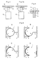
- the lock shown in Fig. 1 in horizontal section is mounted in a passage 1 with two boundary walls 2, 3.
- On the wall 2 is a fixed, cylindrical wall 4 with an approximately semicircular, open against the wall 3 Cross section assembled and boarded by plates 5, 6.
- a semicircular jacket 8 is rotatable about the cylinder axis 7 of the wall 4.
- the jacket 8 has a slightly smaller outer diameter than the inner diameter of the wall 4.
- Symmetrical to the wall 4 a hinged door 9 is attached to the opposite boundary wall 3 by means of a hinge 10. At its free edge, this projects in the closed position with a brush seal 11 to the path of the jacket 8; the seal 11 is thus at a distance from the axis of rotation 7 which corresponds approximately to the radius of the jacket 8.
- the jacket 8 has two windows 12 and the door 9 another window 13.
- the round base plate 14 of the lock rests on three load cells 15, which together act as a balance.
- An identification device 16 is installed in the plate 6 on the outside of the passage 1. This can include, for example, a card reader or a keyboard for entering a code.
- An intercom can also be installed.
- a switch 19 and two indicator lamps 20 are arranged on a column 18 within the lock room. The two free edges of the plates 5, 6 carry contact strips 21.
- FIG. 2 shows an axial section through the upper part of the lock.
- a frame consisting of two ring-shaped, Rectangular tubes 27, 28 which are spaced apart from one another and connected via vertical stands 29 and spokes 30 projecting inwards from the upper tube 27.
- the lower tube 28 is screwed to the wall 4.
- the spokes 30 carry a central axle body 31.
- This carries a stationary cover plate 32 of the interior of the lock at its lower end.
- a lamp 33 is attached to the cover plate 32, as is a light barrier 34 which is directed into the interior of the lock and emits a signal when a person is present.
- a turntable 38 is rotatably mounted on the axle body 31.
- the turntable 38 carries a plate 39.
- a carrier 45 is fastened to the axle body 31 below the turntable 38. On the one hand, this carries a reversible electric geared motor 46, which drives a pinion 48 via a magnetic coupling 47. The pinion 48 meshes with a ring gear 49 on the circumference of the turntable 38.
- the clutch 47 is disengaged in the de-energized state. It can be followed by a slip clutch to increase safety.
- An electromagnet 52 is also fastened to the carrier 45 with a locking plunger 53. When the magnet is excited, the plunger 53 is in the position shown in FIG.
- a cable drum 64 is integrally formed on the turntable 38 at the upper end.
- a pull rope 65 is wound on it and guided over a rope pulley 66.
- the rope 65 is tensioned by a weight 67. Instead of the weight 67, however, a tension spring could also be arranged.
- FIG. 4 shows a section of the locking of the door 9.
- the door 9 strikes against a bar 71 fastened to a cover plate 70.
- the door 9 has a recess in its upper edge 72.
- a locking plunger 73 of an electromagnet 74 engages in this.
- the plunger 73 has at the bottom an inclined surface 75, against which the door edge runs when it closes.
- the magnet 74 is energized, the plunger 73 is in the disengaged position shown in FIG. 4.
- the magnet 74 is de-energized, it is engaged.
- the door 9, like the jacket 8, can be preloaded into the open position by a weight or a spring.
- a limit switch is expediently provided to indicate the closed position of the door 9.
- Fig. 5 The operation of the lock described is shown in Fig. 5.
- the jacket 8 forms a full circle with the wall 4 and the lock is not accessible from either side.
- the clutch 47, the magnet 52 and the magnet 74 are energized and thus the casing 8 and the door 9 are locked.
- a signal is present at the associated switch 60.
- the switch 17 Via the control, the magnet 52 is now first de-energized and the motor 46 is driven in the appropriate direction of rotation. As soon as the signal at the switch 60 drops, the magnet 52 is excited again. The jacket 8 rotates in the direction B. Immediately before this position is reached, the plunger 53 runs on the wedge 56 and actuates the limit switch 55. The signal from this switch sets the Engine 46 off. The run-out distance is dimensioned such that when the motor 46 is stopped, the tappet 53 engages behind the wedge 56 and position B is thus locked. Now the person enters the lock, which is determined by the scale 15 and the light barrier 34.
- pressing the switch 19 triggers the rotation of the jacket 8 in the opposite direction, for which purpose the magnet 52 is briefly de-energized.
- the magnet 52 is again briefly de-energized by a signal from the associated switch 60, so that the jacket 8 moves directly via position A to position C, in which the lock is open to the outside.
- the motor 46 is switched off and the lock locked in the manner described above.
- the passage from the outside occurs in an analogous manner, except that the access authorization is first determined here via the identification device 16.
- the signal of the switch 19 for pivoting into position B is accepted, the signal of the scale 15 can be checked for an upper limit value so that access by two people is prevented at the same time becomes. For example, individual lower and upper limit values for their weight could be stored for the persons authorized to access.
- the fourth position D of the jacket 8, in which the lock is open to both sides, is blocked in normal operation.
- This lock can, however, be released, for example, from a porter's lodge or using a special key or code, for example in the event of an alarm or if bulky goods have to be transported through passage 1. If, for example, rods have to be transported through passage 1, the swiveling of the casing 8 into position D is sufficient.
- the door 9 is additionally unlocked and opened. For a given passage width, the door 9 can therefore be made narrow compared to known locks because the shell radius is added to its opening.
- the security gate according to the invention can thus be installed in a very space-saving manner even in narrow passages 1.
- Both the clutch 47 and the magnet 52 are de-energized to open the lock.
- the weight 67 then pulls the sheath 8 into the position D via the rope 65 and the drum 64. Because no electrical drive is required for this purpose, the safe opening of the lock is guaranteed in the event of an alarm even in the event of a power failure.
- the associated contact strip 21 responds and briefly switches the motor 46 to the opposite direction of rotation.
- the motor 46 can switch on again in the original direction of rotation either after a delay or after actuating the switch 19 again.
Landscapes
- Engineering & Computer Science (AREA)
- Civil Engineering (AREA)
- Structural Engineering (AREA)
- Lock And Its Accessories (AREA)
- Pipe Accessories (AREA)
- Wing Frames And Configurations (AREA)
Priority Applications (3)
| Application Number | Priority Date | Filing Date | Title |
|---|---|---|---|
| EP88810711A EP0364648B1 (fr) | 1988-10-18 | 1988-10-18 | Sas pour le passage de personnes |
| DE8888810711T DE3878911D1 (de) | 1988-10-18 | 1988-10-18 | Personenschleuse. |
| AT88810711T ATE86352T1 (de) | 1988-10-18 | 1988-10-18 | Personenschleuse. |
Applications Claiming Priority (1)
| Application Number | Priority Date | Filing Date | Title |
|---|---|---|---|
| EP88810711A EP0364648B1 (fr) | 1988-10-18 | 1988-10-18 | Sas pour le passage de personnes |
Publications (2)
| Publication Number | Publication Date |
|---|---|
| EP0364648A1 true EP0364648A1 (fr) | 1990-04-25 |
| EP0364648B1 EP0364648B1 (fr) | 1993-03-03 |
Family
ID=8200612
Family Applications (1)
| Application Number | Title | Priority Date | Filing Date |
|---|---|---|---|
| EP88810711A Expired - Lifetime EP0364648B1 (fr) | 1988-10-18 | 1988-10-18 | Sas pour le passage de personnes |
Country Status (3)
| Country | Link |
|---|---|
| EP (1) | EP0364648B1 (fr) |
| AT (1) | ATE86352T1 (fr) |
| DE (1) | DE3878911D1 (fr) |
Cited By (2)
| Publication number | Priority date | Publication date | Assignee | Title |
|---|---|---|---|---|
| EP0621394A3 (fr) * | 1993-04-16 | 1995-05-31 | Gallenschuetz Sicherheitstech | Sas pour le passage de personnes. |
| FR2892760A1 (fr) * | 2005-10-28 | 2007-05-04 | Pro Tech Securite Sarl | Sas pour l'acces a une zone securisee |
Citations (6)
| Publication number | Priority date | Publication date | Assignee | Title |
|---|---|---|---|---|
| GB191001229A (en) * | 1910-01-17 | 1911-01-17 | Howard Crunden Cleaver | Improvements in and relating to Draught Excluding Doors. |
| FR1089960A (fr) * | 1953-06-02 | 1955-03-25 | Porte à tambour | |
| US3914902A (en) * | 1974-07-01 | 1975-10-28 | Hardware Specialties Sales Co | Turnstile |
| FR2416998A1 (fr) * | 1978-02-14 | 1979-09-07 | Doernemann Carola | Cabine de controle de passage de personnes |
| DE3233843C1 (de) * | 1982-09-11 | 1984-01-05 | Eugen Gallenschütz Metallbau KG, 7580 Bühl | Sicherheits-Personenschleuse |
| CH660768A5 (en) * | 1983-05-20 | 1987-06-15 | Hammer Genossenschaft | Gate for people |
-
1988
- 1988-10-18 DE DE8888810711T patent/DE3878911D1/de not_active Expired - Fee Related
- 1988-10-18 AT AT88810711T patent/ATE86352T1/de not_active IP Right Cessation
- 1988-10-18 EP EP88810711A patent/EP0364648B1/fr not_active Expired - Lifetime
Patent Citations (6)
| Publication number | Priority date | Publication date | Assignee | Title |
|---|---|---|---|---|
| GB191001229A (en) * | 1910-01-17 | 1911-01-17 | Howard Crunden Cleaver | Improvements in and relating to Draught Excluding Doors. |
| FR1089960A (fr) * | 1953-06-02 | 1955-03-25 | Porte à tambour | |
| US3914902A (en) * | 1974-07-01 | 1975-10-28 | Hardware Specialties Sales Co | Turnstile |
| FR2416998A1 (fr) * | 1978-02-14 | 1979-09-07 | Doernemann Carola | Cabine de controle de passage de personnes |
| DE3233843C1 (de) * | 1982-09-11 | 1984-01-05 | Eugen Gallenschütz Metallbau KG, 7580 Bühl | Sicherheits-Personenschleuse |
| CH660768A5 (en) * | 1983-05-20 | 1987-06-15 | Hammer Genossenschaft | Gate for people |
Cited By (2)
| Publication number | Priority date | Publication date | Assignee | Title |
|---|---|---|---|---|
| EP0621394A3 (fr) * | 1993-04-16 | 1995-05-31 | Gallenschuetz Sicherheitstech | Sas pour le passage de personnes. |
| FR2892760A1 (fr) * | 2005-10-28 | 2007-05-04 | Pro Tech Securite Sarl | Sas pour l'acces a une zone securisee |
Also Published As
| Publication number | Publication date |
|---|---|
| DE3878911D1 (de) | 1993-04-08 |
| EP0364648B1 (fr) | 1993-03-03 |
| ATE86352T1 (de) | 1993-03-15 |
Similar Documents
| Publication | Publication Date | Title |
|---|---|---|
| DE602004004600T2 (de) | Einrichtung für die manuelle Entriegelung | |
| DE3028295C2 (fr) | ||
| EP1092829B1 (fr) | Dispositif d'entraînement pour une porte | |
| EP2385197B1 (fr) | Serrure | |
| DE2830936C2 (de) | Sicherheitszelle zur Abwicklung von Bankgeschäften o.dgl. | |
| DE2618543C3 (de) | Vorrichtung zum Ver- und Entriegeln eines Drehkreuzes | |
| DE3233843C1 (de) | Sicherheits-Personenschleuse | |
| EP1849951B2 (fr) | Installation de porte coulissante | |
| EP0110819B1 (fr) | Dispositif pour séparer les personnes à l'entrée d'un domaine | |
| EP1160399B1 (fr) | Serrure commandée électriquement | |
| DE9413062U1 (de) | Riegel | |
| DE102015000611B4 (de) | Verriegelungsvorrichtung für eine Tür | |
| EP0364648B1 (fr) | Sas pour le passage de personnes | |
| DE2803765A1 (de) | Drehtuer | |
| CH675145A5 (en) | Turnstile controlling entry to protected area - has fixed semicircular wall at limiting wall of passage coaxial to which semicircular casing is rotatable into four positions | |
| DE3332957A1 (de) | Automatische tuer, insbesondere als zugangstuer zu einer verkaufsflaeche | |
| EP0363618B1 (fr) | Tourniquet | |
| DE2539779A1 (de) | Personen-kontrollschleuse | |
| DE19631064A1 (de) | Fluchttürüberwachung | |
| DE3730031A1 (de) | Drehtuer | |
| DE102004001712A1 (de) | Elektroschloss für ein Tor | |
| EP0410299B1 (fr) | Dispositif de verrouillage et tourniquet pourvu d'un tel dispositif | |
| DE10141313A1 (de) | Öffnungssicherung für ein automatisches Schiebetürsystem | |
| DE4426902A1 (de) | Elektronisches Schloß bzw. Türöffner für Magnetkarten | |
| DE3502759C2 (de) | Einbruchwarngerät eines Garagenschwingtors |
Legal Events
| Date | Code | Title | Description |
|---|---|---|---|
| PUAI | Public reference made under article 153(3) epc to a published international application that has entered the european phase |
Free format text: ORIGINAL CODE: 0009012 |
|
| AK | Designated contracting states |
Kind code of ref document: A1 Designated state(s): AT BE DE FR GB IT LU NL SE |
|
| 17P | Request for examination filed |
Effective date: 19900827 |
|
| 17Q | First examination report despatched |
Effective date: 19910306 |
|
| GRAA | (expected) grant |
Free format text: ORIGINAL CODE: 0009210 |
|
| AK | Designated contracting states |
Kind code of ref document: B1 Designated state(s): AT BE DE FR GB IT LU NL SE |
|
| REF | Corresponds to: |
Ref document number: 86352 Country of ref document: AT Date of ref document: 19930315 Kind code of ref document: T |
|
| ITF | It: translation for a ep patent filed | ||
| GBT | Gb: translation of ep patent filed (gb section 77(6)(a)/1977) |
Effective date: 19930304 |
|
| REF | Corresponds to: |
Ref document number: 3878911 Country of ref document: DE Date of ref document: 19930408 |
|
| ET | Fr: translation filed | ||
| EPTA | Lu: last paid annual fee | ||
| PLBE | No opposition filed within time limit |
Free format text: ORIGINAL CODE: 0009261 |
|
| STAA | Information on the status of an ep patent application or granted ep patent |
Free format text: STATUS: NO OPPOSITION FILED WITHIN TIME LIMIT |
|
| 26N | No opposition filed | ||
| EAL | Se: european patent in force in sweden |
Ref document number: 88810711.7 |
|
| PGFP | Annual fee paid to national office [announced via postgrant information from national office to epo] |
Ref country code: FR Payment date: 19960911 Year of fee payment: 9 |
|
| PGFP | Annual fee paid to national office [announced via postgrant information from national office to epo] |
Ref country code: BE Payment date: 19960919 Year of fee payment: 9 |
|
| PGFP | Annual fee paid to national office [announced via postgrant information from national office to epo] |
Ref country code: GB Payment date: 19960920 Year of fee payment: 9 |
|
| PGFP | Annual fee paid to national office [announced via postgrant information from national office to epo] |
Ref country code: SE Payment date: 19960924 Year of fee payment: 9 |
|
| PGFP | Annual fee paid to national office [announced via postgrant information from national office to epo] |
Ref country code: NL Payment date: 19961031 Year of fee payment: 9 |
|
| PG25 | Lapsed in a contracting state [announced via postgrant information from national office to epo] |
Ref country code: GB Free format text: LAPSE BECAUSE OF NON-PAYMENT OF DUE FEES Effective date: 19971018 |
|
| PG25 | Lapsed in a contracting state [announced via postgrant information from national office to epo] |
Ref country code: SE Free format text: LAPSE BECAUSE OF NON-PAYMENT OF DUE FEES Effective date: 19971019 |
|
| PG25 | Lapsed in a contracting state [announced via postgrant information from national office to epo] |
Ref country code: FR Free format text: THE PATENT HAS BEEN ANNULLED BY A DECISION OF A NATIONAL AUTHORITY Effective date: 19971031 Ref country code: BE Free format text: LAPSE BECAUSE OF NON-PAYMENT OF DUE FEES Effective date: 19971031 |
|
| PGFP | Annual fee paid to national office [announced via postgrant information from national office to epo] |
Ref country code: LU Payment date: 19980303 Year of fee payment: 10 |
|
| BERE | Be: lapsed |
Owner name: SCHNEEBELI METALLBAU A.G. Effective date: 19971031 |
|
| PG25 | Lapsed in a contracting state [announced via postgrant information from national office to epo] |
Ref country code: NL Free format text: LAPSE BECAUSE OF NON-PAYMENT OF DUE FEES Effective date: 19980501 |
|
| GBPC | Gb: european patent ceased through non-payment of renewal fee |
Effective date: 19971018 |
|
| NLV4 | Nl: lapsed or anulled due to non-payment of the annual fee |
Effective date: 19980501 |
|
| EUG | Se: european patent has lapsed |
Ref document number: 88810711.7 |
|
| REG | Reference to a national code |
Ref country code: FR Ref legal event code: ST |
|
| PG25 | Lapsed in a contracting state [announced via postgrant information from national office to epo] |
Ref country code: LU Free format text: LAPSE BECAUSE OF NON-PAYMENT OF DUE FEES Effective date: 19981018 |
|
| PGFP | Annual fee paid to national office [announced via postgrant information from national office to epo] |
Ref country code: AT Payment date: 20011010 Year of fee payment: 14 |
|
| PGFP | Annual fee paid to national office [announced via postgrant information from national office to epo] |
Ref country code: DE Payment date: 20011029 Year of fee payment: 14 |
|
| PG25 | Lapsed in a contracting state [announced via postgrant information from national office to epo] |
Ref country code: AT Free format text: LAPSE BECAUSE OF NON-PAYMENT OF DUE FEES Effective date: 20021018 |
|
| PG25 | Lapsed in a contracting state [announced via postgrant information from national office to epo] |
Ref country code: DE Free format text: LAPSE BECAUSE OF NON-PAYMENT OF DUE FEES Effective date: 20030501 |
|
| PG25 | Lapsed in a contracting state [announced via postgrant information from national office to epo] |
Ref country code: IT Free format text: LAPSE BECAUSE OF NON-PAYMENT OF DUE FEES Effective date: 20051018 |