EP0364721A1 - Lanze zum Blasfrischen - Google Patents
Lanze zum Blasfrischen Download PDFInfo
- Publication number
- EP0364721A1 EP0364721A1 EP89116607A EP89116607A EP0364721A1 EP 0364721 A1 EP0364721 A1 EP 0364721A1 EP 89116607 A EP89116607 A EP 89116607A EP 89116607 A EP89116607 A EP 89116607A EP 0364721 A1 EP0364721 A1 EP 0364721A1
- Authority
- EP
- European Patent Office
- Prior art keywords
- oxygen
- lance
- mouth
- edge
- supplying
- Prior art date
- Legal status (The legal status is an assumption and is not a legal conclusion. Google has not performed a legal analysis and makes no representation as to the accuracy of the status listed.)
- Granted
Links
- 238000007670 refining Methods 0.000 title claims abstract description 13
- QVGXLLKOCUKJST-UHFFFAOYSA-N atomic oxygen Chemical compound [O] QVGXLLKOCUKJST-UHFFFAOYSA-N 0.000 claims abstract description 29
- 229910052760 oxygen Inorganic materials 0.000 claims abstract description 29
- 239000001301 oxygen Substances 0.000 claims abstract description 29
- 229910052751 metal Inorganic materials 0.000 claims abstract description 6
- 239000002184 metal Substances 0.000 claims abstract description 6
- 239000007789 gas Substances 0.000 claims description 14
- 238000002485 combustion reaction Methods 0.000 claims description 4
- 230000001105 regulatory effect Effects 0.000 claims description 2
- 238000011144 upstream manufacturing Methods 0.000 claims description 2
- 239000012530 fluid Substances 0.000 description 2
- 239000007788 liquid Substances 0.000 description 2
- 125000006850 spacer group Chemical group 0.000 description 2
- UGFAIRIUMAVXCW-UHFFFAOYSA-N Carbon monoxide Chemical compound [O+]#[C-] UGFAIRIUMAVXCW-UHFFFAOYSA-N 0.000 description 1
- 235000014443 Pyrus communis Nutrition 0.000 description 1
- 229910002091 carbon monoxide Inorganic materials 0.000 description 1
- 210000003679 cervix uteri Anatomy 0.000 description 1
- 238000001816 cooling Methods 0.000 description 1
- 239000012809 cooling fluid Substances 0.000 description 1
- 230000001419 dependent effect Effects 0.000 description 1
- 230000000694 effects Effects 0.000 description 1
- 238000000034 method Methods 0.000 description 1
- XLYOFNOQVPJJNP-UHFFFAOYSA-N water Substances O XLYOFNOQVPJJNP-UHFFFAOYSA-N 0.000 description 1
Images
Classifications
-
- C—CHEMISTRY; METALLURGY
- C21—METALLURGY OF IRON
- C21C—PROCESSING OF PIG-IRON, e.g. REFINING, MANUFACTURE OF WROUGHT-IRON OR STEEL; TREATMENT IN MOLTEN STATE OF FERROUS ALLOYS
- C21C5/00—Manufacture of carbon-steel, e.g. plain mild steel, medium carbon steel or cast steel or stainless steel
- C21C5/28—Manufacture of steel in the converter
- C21C5/42—Constructional features of converters
- C21C5/46—Details or accessories
- C21C5/4606—Lances or injectors
-
- C—CHEMISTRY; METALLURGY
- C21—METALLURGY OF IRON
- C21C—PROCESSING OF PIG-IRON, e.g. REFINING, MANUFACTURE OF WROUGHT-IRON OR STEEL; TREATMENT IN MOLTEN STATE OF FERROUS ALLOYS
- C21C5/00—Manufacture of carbon-steel, e.g. plain mild steel, medium carbon steel or cast steel or stainless steel
- C21C5/28—Manufacture of steel in the converter
- C21C5/30—Regulating or controlling the blowing
- C21C5/305—Afterburning
Definitions
- the present invention relates to a refining lance comprising at least one supersonic nozzle for supplying the refining oxygen to a metal bath, as well as to means for supplying the post-combustion oxygen to the space situated above the bath.
- Refining lances which, apart from the main nozzles supplying the supersonic refining oxygen, several auxiliary nozzles, inclined between 25 ° and 60 ° relative to the vertical axis, delivering jets of subsonic oxygen used for afterburning. It is also known (see patent LU 82,846) to provide the conduits of the nozzles which guide the afterburner oxygen, with means for increasing the degree of turbulence of the jet. These means may consist of sheets placed in the conduits of the nozzles; it is also possible to provide the walls of the conduits with grooves.
- angles of inclination of the afterburning oxygen jets are however imposed by those of the nozzles; once determined by empirical tests or methods (taking into account the inclinations of the primary oxygen jets, their arrangement, the dimensions of the converter, the height of the lance head above the bath, etc.), these angles remain constant. Consequently, these nozzles do not allow either to sweep the space above the bath with jets of oxygen, nor to send the post-combustion oxygen into the converter at an appropriate angle, depending on the refining phase in Classes.
- Patent LU 86,329 describes a supersonic nozzle supplying post-combustion oxygen under variable inclination to the space below. above a metal bath. It has a wall along which the gas flows in a straight line before reaching a sharp edge, constituting a part of the mouth. It is at the height of the summit of this pointed edge that the jet relaxes and is deflected.
- the deflection angle varies as a function of the gas pressure at the edge, i.e. the higher the gas pressure, the greater the angle of deflection; on the other hand the effect of deflection by the edge is practically zero when the gas has a subsonic speed there.
- the object of the present invention is to propose a nozzle which makes it possible to create a continuous layer of oxygen, completely surrounding the jet of refining oxygen.
- a pressure sensor (not shown) measures the actual pressure P at the outlet of the control valve. This pressure P is compared to a set pressure Po and in the event of a difference, a regulation loop acts on the degree of opening of the valve.
- the set pressures Po vary as a function of the refining phase and are chosen so that the space is supplied with oxygen by means of a jet having the required flow rate and opening angle.
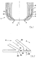
- All around the annular nozzle 6 supplying the afterburning oxygen are the walls which guide the cooling fluid (usually water). These walls are essentially constituted by three concentric tubes 4, 7 and 8, the tube 4 guiding by its inner face also the oxygen used for afterburning. The spacing between the concentric walls 5, 4 and 7, 8 is maintained using the spacers 10 and 9 respectively. These spacers, half a dozen in number per conduit, are preferably elongated flat sheets, so as to also assume a function of guiding the fluids necessary for an even distribution of the fluids in the annular conduits.
- the lance head essentially comprises a central tube 5 which, in the case of the drawing, has a pear shape as explained in connection with patent application LU 86.321, and several concentric tubes 4, 7, 8 which define annular spaces guiding a gas and a liquid. Since the liquid layer is continuous and in particular does not meet any oxygen-supplying nozzles, which are the source of turbulence, the cooling of the external cap is done under optimal conditions.
- the outlet angle of the elbow which is approximately 20 ° relative to the axis of the lance in the case of the figure- defines the angle of deflection of the gas jet in subsonic regime.
- the front face of the head, near the edge 25 is slightly offset towards the inside of the lance head. This offset allows a more pronounced deflection of the supersonic jet by the edge 21.
- the bent surface is extended as far as the front face of the head, it will be necessary to avoid bringing the edge 25 too close to the inclined wall 23 so as not to move the position of the cervix, c. to d. the point of the nozzle where the section is the smallest, at this level.
- the gas jet exits at an angle defined by the bent wall, ie. at an angle of 20 ° in this case. From a limit pressure, the speed of the gas at the outlet becomes sonic. Additional increases in the supply pressure no longer act on the Mach number at the outlet which remains equal to 1, but raise its internal pressure. At the height of the edge 21, the jet relaxes while being the seat of a multitude of Mach lines, which are the basis of an increase in the speed of the jet and its deflection.
- the deflection angle varies as a function of the gas pressure at the edge 21, i.e. the higher the gas pressure, the greater the deflection and the quantity of gas deflected.
- the deflection of the jet by the edge 25 at which the internal pressure has already dropped significantly, is weak, that caused by the edge 22 is most reduced.
- the oxygen layer is tilted towards the surface of the metal bath, sketching a shape comparable to that of an open three-quarter umbrella. A large part of the carbon monoxide leaving the bath must pass through the continuous layer of oxygen before reaching the chimney. Depending on the operating mode (Mach number), the oxygen layer is more or less thick.
Landscapes
- Engineering & Computer Science (AREA)
- Chemical & Material Sciences (AREA)
- Manufacturing & Machinery (AREA)
- Materials Engineering (AREA)
- Metallurgy (AREA)
- Organic Chemistry (AREA)
- Carbon Steel Or Casting Steel Manufacturing (AREA)
- Manufacture And Refinement Of Metals (AREA)
- Treatment Of Steel In Its Molten State (AREA)
- Blow-Moulding Or Thermoforming Of Plastics Or The Like (AREA)
Priority Applications (1)
| Application Number | Priority Date | Filing Date | Title |
|---|---|---|---|
| AT89116607T ATE89321T1 (de) | 1988-09-28 | 1989-09-08 | Lanze zum blasfrischen. |
Applications Claiming Priority (2)
| Application Number | Priority Date | Filing Date | Title |
|---|---|---|---|
| LU87354A LU87354A1 (fr) | 1988-09-28 | 1988-09-28 | Lance d'affinage |
| LU87354 | 1988-09-28 |
Publications (2)
| Publication Number | Publication Date |
|---|---|
| EP0364721A1 true EP0364721A1 (de) | 1990-04-25 |
| EP0364721B1 EP0364721B1 (de) | 1993-05-12 |
Family
ID=19731099
Family Applications (1)
| Application Number | Title | Priority Date | Filing Date |
|---|---|---|---|
| EP89116607A Expired - Lifetime EP0364721B1 (de) | 1988-09-28 | 1989-09-08 | Lanze zum Blasfrischen |
Country Status (4)
| Country | Link |
|---|---|
| EP (1) | EP0364721B1 (de) |
| AT (1) | ATE89321T1 (de) |
| DE (1) | DE68906505T2 (de) |
| LU (1) | LU87354A1 (de) |
Cited By (2)
| Publication number | Priority date | Publication date | Assignee | Title |
|---|---|---|---|---|
| EP0490101A1 (de) * | 1990-12-10 | 1992-06-17 | Arbed S.A. | Blaslanze |
| FR2797738A1 (fr) * | 1999-08-18 | 2001-02-23 | Air Liquide | Procede d'injection d'un gaz supersonique dans un four a arc electrique et four a arc pour la mise en oeuvre de ce procede |
Citations (4)
| Publication number | Priority date | Publication date | Assignee | Title |
|---|---|---|---|---|
| EP0055956A1 (de) * | 1980-12-22 | 1982-07-14 | INSTITUT DE RECHERCHES DE LA SIDERURGIE FRANCAISE (IRSID) France | Lanze zum Einblasen eines oxydierenden Gases, speziell von Sauerstoff, zur Behandlung von Metallschmelzen |
| DE3134244A1 (de) * | 1980-10-13 | 1982-07-22 | ARBED S.A., 2930 Luxembourg | "sauerstoff-blaslanze" |
| EP0234388A2 (de) * | 1986-02-25 | 1987-09-02 | Arbed S.A. | Sauerstoff-Blaslanze |
| EP0234389A2 (de) * | 1986-02-28 | 1987-09-02 | Arbed S.A. | Düse für Frischlanzen |
-
1988
- 1988-09-28 LU LU87354A patent/LU87354A1/fr unknown
-
1989
- 1989-09-08 EP EP89116607A patent/EP0364721B1/de not_active Expired - Lifetime
- 1989-09-08 AT AT89116607T patent/ATE89321T1/de not_active IP Right Cessation
- 1989-09-08 DE DE89116607T patent/DE68906505T2/de not_active Expired - Fee Related
Patent Citations (4)
| Publication number | Priority date | Publication date | Assignee | Title |
|---|---|---|---|---|
| DE3134244A1 (de) * | 1980-10-13 | 1982-07-22 | ARBED S.A., 2930 Luxembourg | "sauerstoff-blaslanze" |
| EP0055956A1 (de) * | 1980-12-22 | 1982-07-14 | INSTITUT DE RECHERCHES DE LA SIDERURGIE FRANCAISE (IRSID) France | Lanze zum Einblasen eines oxydierenden Gases, speziell von Sauerstoff, zur Behandlung von Metallschmelzen |
| EP0234388A2 (de) * | 1986-02-25 | 1987-09-02 | Arbed S.A. | Sauerstoff-Blaslanze |
| EP0234389A2 (de) * | 1986-02-28 | 1987-09-02 | Arbed S.A. | Düse für Frischlanzen |
Cited By (3)
| Publication number | Priority date | Publication date | Assignee | Title |
|---|---|---|---|---|
| EP0490101A1 (de) * | 1990-12-10 | 1992-06-17 | Arbed S.A. | Blaslanze |
| AU644486B2 (en) * | 1990-12-10 | 1993-12-09 | Arbed S.A. | Top blowing refining lance |
| FR2797738A1 (fr) * | 1999-08-18 | 2001-02-23 | Air Liquide | Procede d'injection d'un gaz supersonique dans un four a arc electrique et four a arc pour la mise en oeuvre de ce procede |
Also Published As
| Publication number | Publication date |
|---|---|
| LU87354A1 (fr) | 1990-04-06 |
| ATE89321T1 (de) | 1993-05-15 |
| EP0364721B1 (de) | 1993-05-12 |
| DE68906505D1 (de) | 1993-06-17 |
| DE68906505T2 (de) | 1993-10-07 |
Similar Documents
| Publication | Publication Date | Title |
|---|---|---|
| EP2085488B1 (de) | Device for blowing gas onto a surface of a material in running strips | |
| EP1270101B1 (de) | Dünne und verteilte rohrförmige Struktur und Herstellungsverfahren | |
| LU86322A1 (fr) | Lance de soufflage d'oxygene | |
| FR2468379A1 (fr) | Dispositif nebuliseur permettant de faire varier la concentration en oxygene d'un aerosol | |
| EP0291372B1 (de) | Gasbrenner mit kalter Düse | |
| EP0364721B1 (de) | Lanze zum Blasfrischen | |
| EP0086694B1 (de) | Aufblasbare Injektionslanze für einen metallurgischen Konverter | |
| FR2553879A1 (fr) | Debitmetre a venturi a faibles pertes d'energie | |
| EP0336109A1 (de) | Düse für Frischlanzen | |
| CA1232133A (fr) | Procede pour le rechauffage du gaz de soufflage d'un haut-fourneau par un generateur de plasma | |
| EP4294716B1 (de) | Aufzugserzeugendes system und mit einem solchen system ausgestattetes boot | |
| EP0234389B1 (de) | Düse für Frischlanzen | |
| EP0177423B1 (de) | Innenmischende Schneidbrennerdüse | |
| EP4036457B1 (de) | Speichervorrichtung für ein kryogenes fluid | |
| FR2740862A1 (fr) | Dispositif pour aspirer un fluide gazeux a travers un conduit pour le rejeter a l'exterieur de celui-ci | |
| CA1323756C (fr) | Lance de soufflage d'oxygene | |
| FR2621292A1 (fr) | Structure de quille en liaison avec la coque d'un bateau de navigation | |
| EP0878672B1 (de) | Belüftungssystem mit Lufteinspritzung für einen besseren Zug | |
| EP0364722A1 (de) | Sauertoff-Blaslanze | |
| LU87355A1 (fr) | Lance de soufflage d'oxygene | |
| FR2501623A1 (fr) | Agencement de tuyere pour avion a reaction du type a decollage vertical et/ou a decollage court | |
| FR2583652A1 (fr) | Perfectionnement aux tours de refroidissement des gaz charges de poussieres | |
| EP0926435A1 (de) | Verbesserung an Brennern für festen Brennstoff | |
| FR2515558A1 (fr) | Appareil et procede pour distribuer un abrasif dans un courant de gaz | |
| EP1122115B1 (de) | Vorrichtung zum Betanken eines Kraftstoffbehälters insbesondere für ein Kraftfahrzeug |
Legal Events
| Date | Code | Title | Description |
|---|---|---|---|
| PUAI | Public reference made under article 153(3) epc to a published international application that has entered the european phase |
Free format text: ORIGINAL CODE: 0009012 |
|
| AK | Designated contracting states |
Kind code of ref document: A1 Designated state(s): AT BE DE FR GB IT NL |
|
| 17P | Request for examination filed |
Effective date: 19900907 |
|
| 17Q | First examination report despatched |
Effective date: 19920923 |
|
| GRAA | (expected) grant |
Free format text: ORIGINAL CODE: 0009210 |
|
| AK | Designated contracting states |
Kind code of ref document: B1 Designated state(s): AT BE DE FR GB IT NL |
|
| REF | Corresponds to: |
Ref document number: 89321 Country of ref document: AT Date of ref document: 19930515 Kind code of ref document: T |
|
| REF | Corresponds to: |
Ref document number: 68906505 Country of ref document: DE Date of ref document: 19930617 |
|
| ITF | It: translation for a ep patent filed | ||
| GBT | Gb: translation of ep patent filed (gb section 77(6)(a)/1977) |
Effective date: 19930601 |
|
| PGFP | Annual fee paid to national office [announced via postgrant information from national office to epo] |
Ref country code: FR Payment date: 19930824 Year of fee payment: 5 |
|
| PGFP | Annual fee paid to national office [announced via postgrant information from national office to epo] |
Ref country code: DE Payment date: 19930825 Year of fee payment: 5 |
|
| PGFP | Annual fee paid to national office [announced via postgrant information from national office to epo] |
Ref country code: GB Payment date: 19930901 Year of fee payment: 5 |
|
| PGFP | Annual fee paid to national office [announced via postgrant information from national office to epo] |
Ref country code: BE Payment date: 19930906 Year of fee payment: 5 |
|
| PGFP | Annual fee paid to national office [announced via postgrant information from national office to epo] |
Ref country code: AT Payment date: 19930909 Year of fee payment: 5 |
|
| PGFP | Annual fee paid to national office [announced via postgrant information from national office to epo] |
Ref country code: NL Payment date: 19930930 Year of fee payment: 5 |
|
| PG25 | Lapsed in a contracting state [announced via postgrant information from national office to epo] |
Ref country code: GB Effective date: 19940908 Ref country code: AT Effective date: 19940908 |
|
| PG25 | Lapsed in a contracting state [announced via postgrant information from national office to epo] |
Ref country code: BE Effective date: 19940930 |
|
| BERE | Be: lapsed |
Owner name: S.A. ARBED Effective date: 19940930 |
|
| PG25 | Lapsed in a contracting state [announced via postgrant information from national office to epo] |
Ref country code: NL Effective date: 19950401 |
|
| GBPC | Gb: european patent ceased through non-payment of renewal fee |
Effective date: 19940908 |
|
| NLV4 | Nl: lapsed or anulled due to non-payment of the annual fee | ||
| PG25 | Lapsed in a contracting state [announced via postgrant information from national office to epo] |
Ref country code: FR Effective date: 19950531 |
|
| PG25 | Lapsed in a contracting state [announced via postgrant information from national office to epo] |
Ref country code: DE Effective date: 19950601 |
|
| REG | Reference to a national code |
Ref country code: FR Ref legal event code: ST |
|
| PG25 | Lapsed in a contracting state [announced via postgrant information from national office to epo] |
Ref country code: IT Free format text: LAPSE BECAUSE OF NON-PAYMENT OF DUE FEES;WARNING: LAPSES OF ITALIAN PATENTS WITH EFFECTIVE DATE BEFORE 2007 MAY HAVE OCCURRED AT ANY TIME BEFORE 2007. THE CORRECT EFFECTIVE DATE MAY BE DIFFERENT FROM THE ONE RECORDED. Effective date: 20050908 |
|
| PLBE | No opposition filed within time limit |
Free format text: ORIGINAL CODE: 0009261 |
|
| STAA | Information on the status of an ep patent application or granted ep patent |
Free format text: STATUS: NO OPPOSITION FILED WITHIN TIME LIMIT |